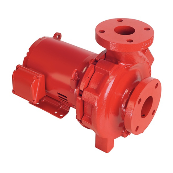
Armstrong 4200H Installation And Operating Instructions Manual
Design envelope, end suction horizontal
pumping units with
ivs drive
Hide thumbs
Also See for 4200H:
- Installation and operating instructions manual (46 pages) ,
- Installation and operating instructions manual (64 pages)

Subscribe to Our Youtube Channel
Related Manuals for Armstrong 4200H


Summary of Contents for Armstrong 4200H
- Page 1 Design Envelope 4200H & 4280 End suction horizontal pumping units with ivs drive Installation and operating instructions File No: 103.80 Date: january 21, 2019 Supersedes: 103.80 Date: august 08, 2018...
-
Page 3: Table Of Contents
4.3.11 data logging 1.1.7 warranty 4 . 4 web interface 1.1.8 uncrating 4.4.1 connecting via ethernet 1.1.9 handling design envelope 4200H & 4.4.2 connecting via wifi 4280 pumping units 1. 2 mechanical installation 4.4.3 switching frequency 1.2.1 location 4 .5 design envelope flow readout tolerance 1.2.2... -
Page 4: Introduction
This manual contains specific information regarding the safe pump casing temperatures may exceed 100°c/212°f and not installation, operation and maintenance of Armstrong Design withstanding pump insulation techniques appropriate mea- Envelope pumps. Read this manual carefully before installing or sures must be taken to minimize risk for operating personnel. -
Page 5: Vibration Levels
4280 pumping units rial and covering the flanges is acceptable. When returning to Design Envelope pumping units Series de 4200H end-suction service be sure to remove the drying agent from the pump. base mounted & de 4280 end-suction close coupled units bring the convenience of ‘plug &... -
Page 6: Mechanical Installation
Horizontal Design Envelope pumping units are supplied with rigid split couplings (DE 4200H) or are close-coupled (DE 4280), as such no alignment is necessary in the field. -
Page 7: Grouting
Never connect a pump to piping, unless extra care is taken to Alignment on a Design Envelope 4200H unit may be verified by measure and align the piping flanges well. Always start piping assuring an equal and parallel gap between coupling halves on from pump. -
Page 8: Electrical Setup
& Design Envelope 4200h & 4280 operati ng instruction s End Suction Horizontal Pumping Units 2.0 electrical setup precautions To avoid the ivs unit getting overheated, the ambient remove cover temperature is not to exceed 133°f (45°c) average Remove front cover to access mains and grounding connec- daily temperature. -
Page 9: Start / Stop Of Pump
The inverter must be protected against short-circuit to avoid exceed one-time per minute. electrical or fire hazard. Armstrong recommends using the fuses detailed in the separate ivs Operating Instructions to pro- If a higher number of starts/stops is required then the start/... -
Page 10: Relay Connections
& Design Envelope 4200h & 4280 o p er a t i n g i nstr u ct ion s End Suction Horizontal Pumping Units fig . 2 . 2 Mains and grounding connections for a5 units fig . - Page 11 Design Envelope 4200h & 4280 insta l l a t io n & opera ting in str u ct io n s End Suction Horizontal Pumping Units fig . 2 .5 Relay connection: terminals for a5 , b1 and b2 units fig .
-
Page 12: Electrical And Control Connections
& Design Envelope 4200h & 4280 operati ng instruction s End Suction Horizontal Pumping Units 2 .3 .5 electrical and control connections fig . 2 . 8 Diagram showing all electrical connections *Note: Terminal 37 is not available on Design Envelope pumps... -
Page 13: Control Terminals
When replacing the front cover, please ensure proper fasten- Analogue Input Reference (0-10V)* ing by applying a torque of 2 Nm. Digital Input Start Design Envelope 4200h & 4280 Analogue Input Feedback (0-10V)* in sta l l a t io n & Digital Input Pump Operating Mode 4.8.2 CONTROL TERMINALS... - Page 14 & Design Envelope 4200h & 4280 operati ng instruction s End Suction Horizontal Pumping Units webserver configur ation Pump in the left side-menu Select For Digital Inputs (A, B) that have been wired: For Digital Functions (E, F) that have been wired:...
-
Page 15: Design Envelope Pump
Design Envelope 4200h & 4280 in sta ll a t io n & operating in struct io ns End Suction Horizontal Pumping Units 2. 4 design envelope pump 2.4.2 can bus wiring controller wiring Connections, Low, High, and Ground as per fig. 2.10. If the depc requires a can bus connection, ensure that the terminating resistor switch is set fig . -
Page 16: Networking Controls
& Design Envelope 4200h & 4280 operati ng instruction s End Suction Horizontal Pumping Units 3 .0 networking controls For connection to the building automation system (ba s), the pump needs to be properly configured to the network. En- sure the r s485 cable is connected to the controller board (fig.2 .10). -
Page 17: Modbus Ip & Rtu
Design Envelope 4200h & 4280 insta l l a t io n & opera ting in str u ct io n s End Suction Horizontal Pumping Units 3 .1 modbus ip & rtu function code change start modbus # of... - Page 18 & Design Envelope 4200h & 4280 operati ng instruction s End Suction Horizontal Pumping Units function code change start modbus # of data read write description during unit notes address register registers t ype oper ation 0×01 0×03 0×05 0×0 6...
- Page 19 Design Envelope 4200h & 4280 insta l l a t io n & opera ting in str u ct io n s End Suction Horizontal Pumping Units function code change start modbus # of data read write description during unit...
-
Page 20: Bacnet Ip & Ms/ Tp
& Design Envelope 4200h & 4280 operati ng instruction s End Suction Horizontal Pumping Units 3 . 2 BACnet ip & ms/ tp object id object name read/ write comments Status av: 1 0 0 Actual speed... - Page 21 Design Envelope 4200h & 4280 insta l l a t io n & opera ting in str u ct io n s End Suction Horizontal Pumping Units object id object name read/ write comments Parameters av:50 0 Standard mode – zero flow head Read Value for standard active mode.
-
Page 22: Operation Start-Up Checklist
Is the system clean? Check rotation arrow prior to operating the unit. The h Is the area around the pump clean? rotation of all Armstrong 4 20 0H & 4 28 0 Vertical In-Line units is clockwise when viewed from behind Warranty the motor (nde). -
Page 23: Touch Screen
Design Envelope 4200h & 4280 insta l l a t io n & opera ting in str u ct io n s End Suction Horizontal Pumping Units 4 .3 touch screen 4 .3 .1 login Default Password 1234 1234 For buildings that are commissioned in multiple stages, or where the design flow changes each time, the Auto Flow Balancing function can be run at the beginning of each stage. -
Page 24: About
& Design Envelope 4200h & 4280 operati ng instruction s End Suction Horizontal Pumping Units 4 .3 .3 about The physical design, software, & user interface are protected by patents & trademarks... -
Page 25: General Settings
Design Envelope 4200h & 4280 insta l l a t io n & opera ting in str u ct io n s End Suction Horizontal Pumping Units 4 .3 . 4 gener al set tings save save... -
Page 26: Manual/Auto Mode
& Design Envelope 4200h & 4280 operati ng instruction s End Suction Horizontal Pumping Units 4 .3 .5 manual /auto mode... -
Page 27: Pump Control
Design Envelope 4200h & 4280 insta l l a t io n & opera ting in str u ct io n s End Suction Horizontal Pumping Units 4 .3 .6 pump control Activate Energy Performance Bundle... - Page 28 & Design Envelope 4200h & 4280 operati ng instruction s End Suction Horizontal Pumping Units Single...
- Page 29 Design Envelope 4200h & 4280 insta l l a t io n & opera ting in str u ct io n s End Suction Horizontal Pumping Units Pressure Sensor Control Pump is now setup for Pres- sure Sensor Control.
-
Page 30: Alarms & Warnings
& Design Envelope 4200h & 4280 o p er a t i n g i nstr u ct ion s End Suction Horizontal Pumping Units Pump is now setup for 2 Sensor Control... -
Page 31: Trend-Graph
Design Envelope 4200h & 4280 insta l l a t io n & opera ting in str u ct io n s End Suction Horizontal Pumping Units 4.3.8 trend-graph There are 3 parameters that can be trended on the touch screen interface: •... -
Page 32: Touch Screen Calibration
& Design Envelope 4200h & 4280 operati ng i nstr uct ion s End Suction Horizontal Pumping Units 4.3.10 touch screen calibration If you are having issues with the touch screen, including: • Being unable to access items to the edge of the screen •... -
Page 33: Data Logging
Design Envelope 4200h & 4280 insta l l a t io n & opera ting in str u ct io n s End Suction Horizontal Pumping Units 4.3.11 data logging Data logs can be used for energy performance analyses or to troubleshoot system issues. -
Page 34: Web Interface
& Design Envelope 4200h & 4280 o p er a t i n g i nstr u ct ion s End Suction Horizontal Pumping Units 4 . 4 web interface To access the control modes: Press settings ... -
Page 35: Design Envelope Flow Readout Tolerance
Design Envelope 4200h & 4280 in sta ll a t io n & operating in struct io ns End Suction Horizontal Pumping Units 5 .0 control modes 4 .5 design envelope flow readout 5 .1 constant flow toler ance Design Envelope pumps can be configured to maintain a con- Tolerance on flow and head readings between test stand stant pump flow in a system as the system head varies. -
Page 36: Quadratic Curve Control With
& Design Envelope 4200h & 4280 o p er a t i n g i nstr u ct ion s End Suction Horizontal Pumping Units 5 . 4 quadr atic curve control 5 .6... - Page 37 Tango and dualArm units have Paral- lel Sensorless Pump Control (pspc) pre-programmed in the controls at Armstrong factories. For all other models (except twin pumps), pspc can be enabled aftermarket; please contact your local Armstrong factory for details.
-
Page 38: 12 5 .9 2*100% Capacity Split Units
& Design Envelope 4200h & 4280 operati ng instruction s End Suction Horizontal Pumping Units From the Webserver, choose Settings -> Pump, set control mode to Parallel with the following parameter values: Note that activating Duty-Standby mode effectively disables the energy efficient staging of Parallel Sensorless operation. -
Page 39: General Care
4200h split coupled vertical in-line pump installed, ensure water is flowing through the sight flow indicator and that filter cartridges are replaced as recommend- ed. (See Armstrong files 43 . 85 and 43 . 86 for seal environ- mental instructions). 6. 2... - Page 40 Tighten all collar set screws (7) evenly and diagonally. Order replacement motors with locked lower bearing. An important feature of the Design Envelope 4200H pump is h Use Allan wrench and insert the coupling screw into posi- that the design permits removal of the mechanical seal without tioning hole (21) to prevent pump shaft rotation and replace disturbing the pump, motor or electrical wiring.
-
Page 41: Mechanical Seal Replacement Instructions For 4280 Close Coupled Vertical In-Line Pump
Design Envelope 4200h & 4280 insta l l a t io n & opera ting in str u ct io n s End Suction Horizontal Pumping Units 6.3 . 2 mechanical seal replacement 7 Replace the adapter, taking care that the seal seat is carefully guided over the shaft. -
Page 42: Warnings And Alarms
Armstrong Technical Service representative. Internal vsd An internal error in the vsd has occurred. If the alarm persists after cycling power to the pump, contact an Armstrong Technical Service representative. vsd parameter One or more of the parameters to control the vsd are not correct. Check the settings on the control card. If the alarm persists after cycling power to the pump, contact an Armstrong Technical Service representative. -
Page 43: Warning Summary For Interfaces
3 phases. If the warning persists, contact an Armstrong Technical Service representative. Internal vsd voltage An internal voltage generated by vsd is out of range. If the warning persists, contact an Armstrong Technical Service representative. -
Page 44: Fuse And Wire Recommendation
& Design Envelope 4200h & 4280 o p era t ing i nstruct ion s End Suction Horizontal Pumping Units 8.0 fuse and wire recommendation table 1: ul fuses, 20 0 -2 40v... -
Page 45: Pump Manager
Design Envelope 4200h & 4280 i n sta l l a t i o n & o per at i n g i n str uct i o n s End Suction Horizontal Pumping Units 9.0 pump manager cloud smart... - Page 46 t o r o n t o 23 bertrand avenue toronto, ontario canada m1l 2p3 +1 416 755 2291 b u f f a l o 93 east avenue north tonawanda, new york u.s.a. 14120 -6594 +1 716 693 8813 b i r m i n g h a m heywood wharf, mucklow hill halesowen, west midlands...
Need help?
Do you have a question about the 4200H and is the answer not in the manual?
Questions and answers