Advertisement
Advertisement
Table of Contents

Subscribe to Our Youtube Channel
Related Manuals for Serpent F110 SF4


Summary of Contents for Serpent F110 SF4
-
Page 2: Table Of Contents
80 km/h or 50mph. Please follow these guidelines when building and operating this model. The Serpent F110 SF4 should see you in the winners circle in no time. In fact everything associated with this - Parental guidance is required when the builder/user of this car is under 16. - Page 3 hOW TO USE ThE maNUal lINES DESCRIpTION ICONS DESCRIpTION Each step contains a variety of numbers, lines, and symbols. The numbers represent the order in Each step contains a variety of symbols described below. which the parts should be assembled. The lines are described below. Step number;...
-
Page 4: Front Assembly
fRONT aSSEmbly STEp 1 bag 1 M3x5 M3x5 M3x5... - Page 5 STEp 2 STEp 3 As default adjustement of the front ride height should M3x6 be assembled 2x 3x6x1 ride height spacers. The kit includes 4x 3x6x0.5mm ride height spacers M3x6 for fine tuning. 3x6x0.5 3x6x1 M2.5x6 3x6x1 M2.5x6 M3x6 FRONT WHEELBASE LONGER SHORTER FRONT...
- Page 6 STEp 5 STEp 4 M3x8 CASTER INSERTS CHART M3x5 M3x8 + CASTER - CASTER FRONT M3x5 REAR 5X8X2.5 Flanged SERVOSAVER ACKERMANN INSERTS - ACKERMANN + ACKERMANN 5X8X2.5 FORWARD REARWARD Flanged M3x5 M3x6 M3x6 M3x5 M3x5 M3x8 5X8X2.5 Flanged...
- Page 7 STEp 6 STEp 7 bag 2 FRONT CAMBER 4 mm...
- Page 8 STEp 8 STEp 9 Right steering block assembly 3x5x2 Nylock Nut M3 R2.3 M3x8 ACKERMANN POSITION 3x5x0.3 3x5x1 3x5x2 KING PIN INSERTS CHART King pin angle adjustable from 0 to 4 degrees. 0º 1º 2º 3º 4º R2.3 3x5x2 3x5x2 3x5x0.3 3x5x1 R2.3 M3x8 Nylock Nut M3...
- Page 9 STEp 10 STEERING TRACKROD LENGTH 19.5 mm...
-
Page 10: Central Assembly
CENTRal aSSEmbly STEp 11 STEp 12 bag 3 M3x6 M3x6 M3x5 M3x6 M3x5 M3x6 M3x5 M3x6... - Page 11 STEp 13 13.1 13.2 M3x6 M3x8 M3x6 M3x6 M3x8 M3x6 M3x6 M3x8...
- Page 12 STEp 14 STEp 15 bag 4 15.1 To exchange the sidesprings it is needed to remove before the bearing holder. 3x6x2.5 15.2 M3x14 To exchange the sidesprings it is needed to remove M3x5 before the bearing holder assembled in step 15.1. M3x5 M3x14 3x6x2.5...
- Page 13 STEp 16 STEp 17 The carbon plate chamfer must Pivotball be oriented to the lowest side short Insert the pod assembly first, then mount the center pivot M3x5 holder. After assembling, adjust the sidesprings so the pod M3x6 plate is preloaded, and perfectly parallel to the chassisplate.
-
Page 14: Rear Assembly
REaR aSSEmbly STEp 18 STEp 19 18.1 Both bearing holders are not symetrical. Right side one fits a 8mm bore Pivotball LONG ballbearing and the left side one fits a 3/8” bore ball bearing. 3x5x2 18.2 M3x5 M3x8 M3x8 M3x5 M3x6 Pivotball M3x6... - Page 15 STEp 20 bag 5 The Serpent diff washers are polished to be used without further sanding or polishing. Tighten the M4 nut carefully, while always checking the diff action. Don’t overtighten. Check after assembly. As basic setup, It should just be possible to slip the spur gear through by hand, once the wheels are attached.
- Page 16 STEp 21 STEp 22 The M3x8 special head screw is normally enough to hold the wheelhub. However, if you deem it necessary, you can insert a M3X8 Special M3x4 set screw on the other side. 1/4x3/8 Flanged 8x12x3.5 M3x10 Pinion is not included in the kit.
- Page 17 STEp 23 M3X5 M3X5 M3x5...
-
Page 18: Central Ii Assembly
CENTRal II aSSEmbly STEp 24 bag 6 hIgh TRaCTION CONfIgURaTION DEfaUlT lOW TRaCTION CONfIgURaTION OpTIONal Recommended for indoor racing and treated Recommended for general outdoor use track surfaces (for example sugarwater). M3X10 M3X10 M3X10 M3X10 3x5x2 3x5x2 3x5x2 3x5x2 3x7.5x1 3x7.5x1 3x7.5x1 3x5x2... - Page 19 STEp 25 hIgh TRaCTION CONfIgURaTION DEfaUlT lOW TRaCTION CONfIgURaTION OpTIONal M3X6 M3X6 M3X6 M3X6 M3X6 M3X6 M3X6 M3X6 M3X6 M3X6 M3x6 M3x6...
- Page 20 STEp 26 hIgh TRaCTION CONfIgURaTION DEfaUlT lOW TRaCTION CONfIgURaTION OpTIONal 26.1 26.1 STEERING LINK LENGTH STEERING LINK LENGTH 9 mm 24 mm 26.2 Check how many teeth your 26.2 Check how many teeth your M3X6 servo spline has (23, 24 or servo spline has (23, 24 or M3X6 M3X5 25) and use the right levers.
- Page 21 STEp 27 bag 7 If your bodyshell has a vertical surface hIgh TRaCTION CONfIgURaTION DEfaUlT under the inside initial bodyholder position, use the outside position lOW TRaCTION CONfIgURaTION OpTIONal Nut M3 3x5x2 M3x5 M3x5 M3x8 M3x8 M3x8 M3x5 3x5x2 Nut M3 M3x5 M3x8...
- Page 22 STEp 28 STEp 29 29.1 Apply the silicone oil on the inner tube. Use the silicone oil supplied in the kit. For the correct cst value please check the default setupsheet. M3x6 M3x8 3x5x1 M3x6 M3x6 29.2 M3x8 3x5x1 M3x6...
-
Page 23: Shock Assembly
ShOCK aSSEmbly STEp 30 STEp 31 ShOCK bag 30.1 30.2 31.1 Use some silicone oil Use some silicone oil during the assembly. during the assembly. Use some silicone oil Oil the foam fully before during the assembly. final assembly. Completely tighten the nut assembled in step 30.2. - Page 24 STEp 32 STEp 33 STEp 34 Close the shock slowly. 32.1 34.1 Important: do not crossthread! Oil will overflow through the 3x5x1 built-in bleed channel. Tighten carefully until the bottom half sits against the shock body. 34.2 32.2 Insert the o-ring 1) Fill the shock body with inside the spring shock absorber oil.
-
Page 25: Electronics Assembly
ElECTRONICS aSSEmbly STEp 35 STEp 36 bag 8 Use narrow fans that don’t touch the pod plate or the battery holder. Use double sided tape to mount the FANS to the chassis. M3x6 M3x6 M3x6... - Page 26 STEp 37 hIgh TRaCTION CONfIgURaTION DEfaUlT lOW TRaCTION CONfIgURaTION OpTIONal Recommended for general use. recommended for low traction use (dusty asphalt, wet racing). Nylock Nut M3x6 M3x12 M3x12 M3x6 BATTERY MOUNT POSITION To assemble the battery it is needed to remove the M3x6 screw and turn the battery holder . When the battery will be fitted assemble the M3x6 screw.
- Page 27 STEp 38 hIgh TRaCTION CONfIgURaTION DEfaUlT lOW TRaCTION CONfIgURaTION OpTIONal Use double sided tape Nylock Nut to mount the ESC and RX to the chassis. M3x6 M3x6 M3x8 M3x6 Use double sided tape to mount the ESC and RX to the chassis. M3x6 M3x6 Nylock Nut M3...
-
Page 28: Final Assembly
fINal aSSEmbly STEp 39 bag 9 fRONT WINg aSSEmbly DEfaUlT fRONT WINg bIg flapS aSSEmbly OpTIONal The front big flaps create a big amount of downforce. It is recommended not to assemble them as default and use them when more steering is needed. Also it is possible to cut them to adjust the amount of downforce created. - Page 29 STEp 40 STEp 41 bag 10 M2.2x6 REAR WING TOP FLAP ADJUSTMENT M2.2x6 M4x10 M3x10 M2.2x6 M3x10 M4x10...
- Page 30 STEp 42 REAR WING TOP FLAP ADJUSTMENT M3x6 M3x6...
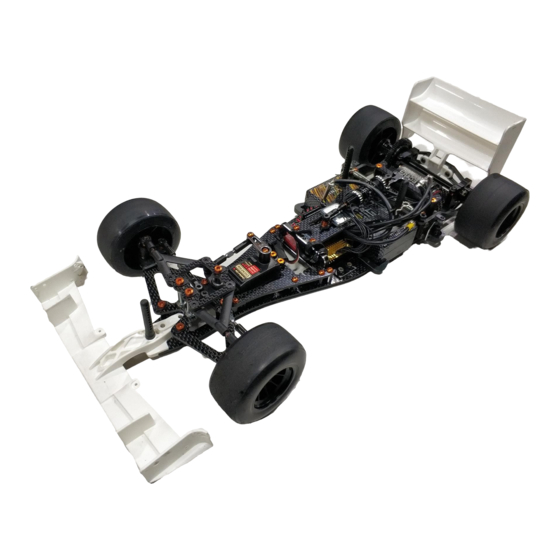
- Page 31 STEp 43 Nylock Nut M4 Flanged The front wheelnuts should not be tightened too much to ensure the wheels turn free. 5x10x4 Nylock Nut M4 Body, wheels and tyres are NOT included Nylock Nut 5x10x4 M4 Flanged The front wheelnuts should not be tightened too much to ensure the wheels turn free.
-
Page 32: Exploded Views
EXplODED VIEWS INDEX fRONT EXplODED VIEW ball DIff EXplODED VIEW REaR EXplODED VIEW ShOCK EXplODED VIEW CENTER EXplODED VIEW fINal EXplODED VIEW TEam SERpENT NETWORK... - Page 33 fRONT EXplODED VIEW 110124 110124 411337 411337 411163 110157 411425 411206 411384 110408 401429 411424 401042 401025 401043 411206 411336 401058 401025 1312 110408 411163 401025 411380 401042 110108 110108 401043 411321 411323 401025 411042 411042 401043 110128 110108 411322 1312 411337 411220 opt...
- Page 34 411107 Diff balls. 1/8 ceramic (12) 120025 Spur diff gear 64P/90T 120030 Spur diff gear 64P/110T 120036 Spur diff gear 48P/84T 411428 Rear axle carbon F110 SF4 120026 Spur diff gear 64P/94T 120032 Spur diff gear 48P/72T 120037 Spur diff gear 48P/88T...
- Page 35 ShOCK EXplODED VIEW 411430 Shock set F110 SF4 411207 110116 411020 401755 411141 411140 411044 411041 411097 411203 411366 opt 411415 411367 401758 411405 411368 opt 411214 opt 411215 opt 411162 411216 opt 110409 411217 opt 411162 411394 411207 411366 Center spring 6.5lbs...
- Page 36 REaR aSSEmbly 411187 110410 401678 411404 411061 110124 110108 411410 411412 110124 411074 110108 411403 411411 110124 411400 411396 411402 110116 110157 401678 1397 110129 110157 411397 110108 411416 401124 110124 411395 411407 411391 411392 411407 411408 110108 110108 110117 110122 110122 411406...
- Page 37 411396 110402 411417 110122 411389 110402 411422 411423 110127 110122 411423 110104 411417 110127 110122 411429 opt 411419 110125 411418 411429 Battery holder brass F110 SF4 411420 Weight 25gr front low F110 SF4 411421 Weight 15gr front up F110 SF4...
- Page 38 fINal aSSEmbly 110156 411292 opt 411312 opt 411354 opt 110405 411355 opt 411369 411370 opt 110403 1315 1315 411352 411352 411298 110156 411352 110190 1315 411352 110405 411352 411353 opt 411293 opt 110102 411294 opt 1315 110403 110161 110190 110109 411292 Rear wing F110 black H DF 411370 Rear wing F110 white M DF 411312 Rear wing F110 white H DF...
- Page 39 NOTES...
-
Page 40: Team Serpent Network
TEam SERpENT NETWORK F110 SF4 SPARE PARTS www.serpent.com/410067/spares/ F110 SF4 OPTIONALS PARTS www.serpent.com/410067/Optionals/ SERPENT TOOLS www.serpent.com/product/Tools/ SERPENT MERCHANDISING www.serpent.com/product/Merchandising/... - Page 41 SERPENT WEBSITE AND BLOG www.serpent.com www.teamserpent.com www.dragon-rc.com SERPENT PROMO PAGES http://promo.serpent.com SERPENT FACEBOOK GROUPS http://promo.serpent.com/indexfb.htm SERPENT ADVANCED MANUALS http://promo.serpent.com/sam/ SERPENT SOCIAL MEDIA www.facebook.com/SerpentMRC www.youtube.com/user/SerpentMRC www.twitter.com/SerpentMRC www.plus.google.com/+SerpentModelcars/posts www.weibo.com/teamserpent...
- Page 42 #78384-1 Manual F110 SF4...
Need help?
Do you have a question about the F110 SF4 and is the answer not in the manual?
Questions and answers