
Subscribe to Our Youtube Channel
Related Manuals for YASKAWA VIPA IM 053ML


Summary of Contents for YASKAWA VIPA IM 053ML
- Page 1 VIPA System SLIO IM | 053-1ML00 | Manual HB300 | IM | 053-1ML00 | en | 18-42 Interface module MECHATROLINK-III - IM 053ML www.vipa.com/en/service-support/manuals...
- Page 2 VIPA GmbH Ohmstr. 4 91074 Herzogenaurach Telephone: +49 9132 744-0 Fax: +49 9132 744-1864 Email: info@vipa.com Internet: www.vipa.com 053-1ML00_000_IM 053ML,1,EN - © 2018...
-
Page 3: Table Of Contents
VIPA System SLIO Table of contents Table of contents General........................5 1.1 Copyright © VIPA GmbH ................. 5 1.2 About this manual..................... 6 1.3 Safety information..................... 7 Basics and mounting..................... 8 2.1 Safety information for users................8 2.2 System conception................... 9 2.2.1 Overview...................... - Page 4 VIPA System SLIO Table of contents 4.9.5 MECHATROLINK message communication sub functions......84 4.9.6 Command sequence................... 86 4.10 Sample application..................87 4.10.1 Overview....................87 4.10.2 Sequence of coupler commands............... 89 4.10.3 Communication structure................90 Appendix....................... 91 A History of changes.................... 93 HB300 | IM | 053-1ML00 | en | 18-42...
-
Page 5: General
VIPA System SLIO General Copyright © VIPA GmbH General 1.1 Copyright © VIPA GmbH All Rights Reserved This document contains proprietary information of VIPA and is not to be disclosed or used except in accordance with applicable agreements. This material is protected by the copyright laws. It may not be reproduced, distributed, or altered in any fashion by any entity (either internal or external to VIPA), except in accord- ance with applicable agreements, contracts or licensing, without the express written con- sent of VIPA and the business management owner of the material. -
Page 6: About This Manual
VIPA System SLIO General About this manual Information product sup- Contact your local VIPA Customer Service Organization representative if you wish to port report errors or questions regarding the contents of this document. If you are unable to locate a customer service centre, contact VIPA as follows: VIPA GmbH, Ohmstraße 4, 91074 Herzogenaurach, Germany Telefax: +49 9132 744-1204 EMail: documentation@vipa.de... -
Page 7: Safety Information
VIPA System SLIO General Safety information CAUTION! Damages to property is likely if these warnings are not heeded. Supplementary information and useful tips. 1.3 Safety information Applications conforming The system is constructed and produced for: with specifications communication and process control general control and automation tasks industrial applications operation within the environmental conditions specified in the technical data... -
Page 8: Basics And Mounting
VIPA System SLIO Basics and mounting Safety information for users Basics and mounting 2.1 Safety information for users Handling of electrostatic VIPA modules make use of highly integrated components in MOS-Technology. These sensitive modules components are extremely sensitive to over-voltages that can occur during electrostatic discharges. -
Page 9: System Conception
VIPA System SLIO Basics and mounting System conception > Overview 2.2 System conception 2.2.1 Overview System SLIO is a modular automation system for assembly on a 35mm mounting rail. By means of the peripheral modules with 2, 4 or 8 channels this system may properly be adapted matching to your automation tasks. -
Page 10: Components
VIPA System SLIO Basics and mounting System conception > Components 2.2.2 Components CPU (head module) Bus coupler (head module) Line extension Periphery modules Accessories CAUTION! Only modules of VIPA may be combined. A mixed operation with third- party modules is not allowed! CPU 01xC With this CPU 01xC, the CPU electronic, input/output components and power supply are integrated to one casing. - Page 11 VIPA System SLIO Basics and mounting System conception > Components Line extension In the System SLIO there is the possibility to place up to 64 modules in on line. By means of the line extension you can divide this line into several lines. Here you have to place a line extension master at each end of a line and the subsequent line has to start with a line extension slave.
-
Page 12: Accessories
VIPA System SLIO Basics and mounting System conception > Accessories 2.2.3 Accessories Shield bus carrier The shield bus carrier (order no.: 000-0AB00) serves to carry the shield bus (10mm x 3mm) to connect cable shields. Shield bus carriers, shield bus and shield fixings are not in the scope of delivery. -
Page 13: Dimensions
VIPA System SLIO Basics and mounting Dimensions 2.3 Dimensions Dimensions CPU 01xC Dimensions CPU 01x Dimensions bus coupler and line extension slave HB300 | IM | 053-1ML00 | en | 18-42... - Page 14 VIPA System SLIO Basics and mounting Dimensions Dimensions line extension master Dimension periphery module Dimensions electronic module Dimensions in mm HB300 | IM | 053-1ML00 | en | 18-42...
-
Page 15: Mounting Bus Coupler
VIPA System SLIO Basics and mounting Mounting bus coupler 2.4 Mounting bus coupler Requirements for UL compliance use – Use for power supply exclusively SELV/PELV power supplies. – The System SLIO must be installed and operated in a housing according to IEC 61010-1 9.3.2 c). There are locking lever at the top side of the bus coupler. - Page 16 VIPA System SLIO Basics and mounting Mounting bus coupler Turn the locking lever upwards, place the bus coupler at the mounting rail and turn the lever downward. Mounting periphery modules Before mounting the periphery modules you have to remove the bus cover at the right side of the bus coupler by pulling it forward.
-
Page 17: Wiring
VIPA System SLIO Basics and mounting Wiring > Wiring bus coupler After mounting the whole system, to protect the backplane bus connectors at the last module you have to mount the bus cover, now. If the last module is a clamp module, for adaptation the upper part of the bus cover is to be removed. - Page 18 VIPA System SLIO Basics and mounting Wiring > Wiring bus coupler Wiring procedure Pin number at the connector Opening for screwdriver Connection hole for wire Insert a suited screwdriver at an angel into the square opening as shown. Press and hold the screwdriver in the opposite direction to open the contact spring. Insert the stripped end of wire into the round opening.
- Page 19 VIPA System SLIO Basics and mounting Wiring > Wiring bus coupler PM - Power module For wires with a core cross-section of 0.08mm up to 1.5mm Pos. Function Type Description not connected DC 24V DC 24V for power section supply GND for power section supply Sys DC 24V DC 24V for electronic section supply...
-
Page 20: Wiring Periphery Modules
VIPA System SLIO Basics and mounting Wiring > Wiring periphery modules Shield attachment Shield bus carrier Shield bus (10mm x 3mm) Shield clamp Cable shield To attach the shield the mounting of shield bus carriers are necessary. The shield bus carrier (available as accessory) serves to carry the shield bus to connect cable shields. - Page 21 VIPA System SLIO Basics and mounting Wiring > Wiring periphery modules Data 240V AC / 30V DC Cross section 0.08 ... 1.5mm (AWG 28 ... 16) Stripping length 10mm Wiring procedure Pin number at the connector Opening for screwdriver Connection hole for wire Insert a suited screwdriver at an angel into the square opening as shown.
-
Page 22: Wiring Power Modules
VIPA System SLIO Basics and mounting Wiring > Wiring power modules Attach the cables with the accordingly stripped cable screen and fix it by the shield clamp with the shield bus. 2.5.3 Wiring power modules Terminal module terminals Power modules are either integrated to the head module or may be installed between the periphery modules. - Page 23 VIPA System SLIO Basics and mounting Wiring > Wiring power modules Wiring procedure Pin number at the connector Opening for screwdriver Connection hole for wire Insert a suited screwdriver at an angel into the square opening as shown. Press and hold the screwdriver in the opposite direction to open the contact spring. Insert the stripped end of wire into the round opening.
- Page 24 VIPA System SLIO Basics and mounting Wiring > Wiring power modules PM - Power module For wires with a core cross-section of 0.08mm up to 1.5mm Pos. Function Type Description not connected DC 24V DC 24V for power section supply GND for power section supply Sys DC 24V DC 24V for electronic section supply...
- Page 25 VIPA System SLIO Basics and mounting Wiring > Wiring power modules Deployment of the power If the 10A for the power section supply is no longer sufficient, you may use the power modules module from VIPA with the order number 007-1AB00. So you have also the possibility to define isolated groups.
-
Page 26: Demounting
VIPA System SLIO Basics and mounting Demounting > Demounting bus coupler Shield attachment Shield bus carrier Shield bus (10mm x 3mm) Shield clamp Cable shield To attach the shield the mounting of shield bus carriers are necessary. The shield bus carrier (available as accessory) serves to carry the shield bus to connect cable shields. - Page 27 VIPA System SLIO Basics and mounting Demounting > Demounting bus coupler For demounting and exchange of a (head) module or a group of modules, due to mounting reasons you always have to remove the electronic module right beside. After mounting it may be plugged again.
-
Page 28: Demounting Periphery Modules
VIPA System SLIO Basics and mounting Demounting > Demounting periphery modules Plug again the electronic module, which you have removed before. Wire your bus coupler. ð Now you can bring your system back into operation. 2.6.2 Demounting periphery modules Proceeding Exchange of an electronic Power-off your system. - Page 29 VIPA System SLIO Basics and mounting Demounting > Demounting periphery modules Turn the locking lever of the module to be exchanged upwards. Pull the module. For mounting turn the locking lever of the module to be mounted upwards. To mount the module put it to the gap between the both modules and push it, guided by the stripes at both sides, to the mounting rail.
- Page 30 VIPA System SLIO Basics and mounting Demounting > Demounting periphery modules Turn all the locking lever of the module group to be exchanged upwards. Pull the module group forward. For mounting turn all the locking lever of the module group to be mounted upwards. To mount the module group put it to the gap between the both modules and push it, guided by the stripes at both sides, to the mounting rail.
-
Page 31: Trouble Shooting - Leds
VIPA System SLIO Basics and mounting Trouble shooting - LEDs 2.7 Trouble shooting - LEDs General Each module has the LEDs RUN and MF on its front side. Errors or incorrect modules may be located by means of these LEDs. In the following illustrations flashing LEDs are marked by ☼. -
Page 32: Installation Guidelines
VIPA System SLIO Basics and mounting Installation guidelines 2.8 Installation guidelines General The installation guidelines contain information about the interference free deployment of a PLC system. There is the description of the ways, interference may occur in your PLC, how you can make sure the electromagnetic compatibility (EMC), and how you manage the isolation. - Page 33 VIPA System SLIO Basics and mounting Installation guidelines Proof the correct fixing of the lead isolation. – Data lines must be laid isolated. – Analog lines must be laid isolated. When transmitting signals with small ampli- tudes the one sided laying of the isolation may be favourable. –...
-
Page 34: General Data
VIPA System SLIO Basics and mounting General data 2.9 General data Conformity and approval Conformity 2014/35/EU Low-voltage directive 2014/30/EU EMC directive Approval Refer to Technical data others RoHS 2011/65/EU Restriction of the use of certain hazardous substances in electrical and electronic equipment Protection of persons and device protection Type of protection IP20... - Page 35 VIPA System SLIO Basics and mounting General data Mounting conditions Mounting place In the control cabinet Mounting position Horizontal and vertical Standard Comment Emitted interference EN 61000-6-4 Class A (Industrial area) Noise immunity EN 61000-6-2 Industrial area zone B EN 61000-4-2 8kV at air discharge (degree of severity 3), 4kV at contact discharge (degree of severity 2) EN 61000-4-3...
-
Page 36: Hardware Description
VIPA System SLIO Hardware description Properties Hardware description 3.1 Properties 053-1ML00 Field bus: MECHATROLINK-III according to IEC 61158, IEC 61784 MECHATROLINK-III coupler for max. 64 periphery modules Supports standard I/O profile (16byte and 64byte mode) Multi slave node with max. 9 stations –... -
Page 37: Structure
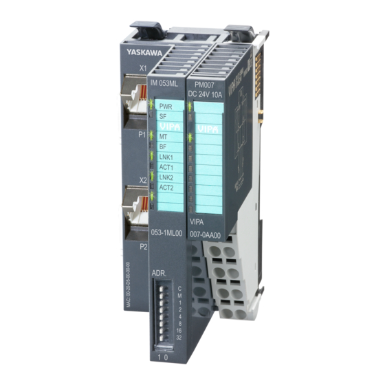
VIPA System SLIO Hardware description Structure > Interfaces 3.2 Structure 053-1ML00 Locking lever terminal module Labeling strip bus interface LEDs bus interface Labeling strip power module LEDs power module Backplane bus DC 24V power section supply Power module X1: MECHATROLINK-III RJ45 bus interface 1 10 X2: MECHATROLINK-III RJ45 bus interface 2 11 Unlocking lever power module 12 Bus interface... -
Page 38: Leds
VIPA System SLIO Hardware description Structure > LEDs PM - Power module For wires with a core cross-section of 0.08mm up to 1.5mm Pos. Function Type Description not connected DC 24V DC 24V for power section supply GND for power section supply Sys DC 24V DC 24V for electronic section supply not connected... - Page 39 VIPA System SLIO Hardware description Structure > LEDs Description green yellow green green green The MECHATROLINK-III coupler is power supplied. No connection can be established to the MECHATROLINK-III master, but there is a physical connection. LK1 or LK2 is on. There is no physical connection to Ethernet.
-
Page 40: Address Switch
VIPA System SLIO Hardware description Structure > Address switch 3.2.3 Address switch Address switch An address may only be assigned once in the MECHATROLINK-III net- work! Changes of the address switch were only recognized after Pow- erON or a Reset! The address set on the address switch must always be identical to the device address in your configuration tool! The address switch serves for the following settings:... -
Page 41: Technical Data
VIPA System SLIO Hardware description Technical data 3.3 Technical data Order no. 053-1ML00 Type IM 053ML - MECHATROLINK Module ID Technical data power supply Power supply (rated value) DC 24 V Power supply (permitted range) DC 20.4...28.8 V Reverse polarity protection ü... - Page 42 VIPA System SLIO Hardware description Technical data Order no. 053-1ML00 Number of participants, max. Node addresses Transmission speed, min. 100 Mbit/s Transmission speed, max. 100 Mbit/s Address range inputs, max. 492 Byte Address range outputs, max. 492 Byte Number of TxPDOs, max. Number of RxPDOs, max.
- Page 43 VIPA System SLIO Hardware description Technical data Order no. 053-1ML00 UL certification in preparation KC certification in preparation HB300 | IM | 053-1ML00 | en | 18-42...
-
Page 44: Deployment
VIPA System SLIO Deployment Basics MECHATROLINK-III Deployment 4.1 Basics MECHATROLINK-III Transfer medium MECHATROLINK-III is compatible to Ethernet in accordance with the IEEE standards. Connection can be either point-to-point or in cascade or star topology. For use in star top- ology, always use a hub module. The specification of MECHATROLINK-III is listed below. Parameter Properties Transfer cable... -
Page 45: Mechatrolink-Iii Installation Guidelines
VIPA System SLIO Deployment MECHATROLINK-III installation guidelines > Topology 4.2 MECHATROLINK-III installation guidelines Generals to data security The topic of data security and access protection have become increasingly important in the industrial environment. The increased networking of entire industrial systems to the network levels within the company together with the functions of remote mainte- nance have all served to increase vulnerability. - Page 46 Deployment MECHATROLINK-III installation guidelines > Topology Star If you connect communication devices to a Hub module like YASKAWA JEPMC- MT2000-E with more than 2 MECHATROLINK-III interfaces, you automatically create a star network topology. If an individual MECHATROLINK-III device fails, this does not automatically lead to failure of the entire network, in contrast to other structures.
-
Page 47: Accessing The System Slio
VIPA System SLIO Deployment Accessing the System SLIO > Supported modules 4.3 Accessing the System SLIO 4.3.1 Supported modules Hardware revision Please note that modules are only supported which are starting from the specified hardware revision. This corresponds to the FPGA version V228 or higher of the module. - Page 48 VIPA System SLIO Deployment Accessing the System SLIO > Supported modules Analog input modules HW rev. 031-1BB10 2 inputs 12bit, current 0(4) ... 20mA, 2 wire 031-1BB30 2 inputs 12bit, voltage 0 ... 10V 031-1BB40 2 inputs 12bit, current 0(4) ... 20mA 031-1BB60 2 inputs 12bit, current 0(4) ...
-
Page 49: Overview
VIPA System SLIO Deployment Accessing the System SLIO > Overview Counter modules HW rev. 050-1BB30 2 Counter 32bit (AB), DC 24V 050-1BB40 Frequency measurement, 2 channels 24Bit, DC 24V Power supply modules HW rev. 007-1AB00 Power supply DC 24V, 10A 007-1AB10 Power supply DC 24V, 4A, backplane bus 5V, 2A Distribution modules... -
Page 50: Example
VIPA System SLIO Deployment Accessing the System SLIO > Example 4.3.3 Example System In the following an example of accessing to the System SLIO is shown. Coupler 053-1ML00 The coupler 053-1ML00 uses 12bytes each and uses the address extension 00h Periphery modules The coupler 053-1ML00 automatically determines the peripheral modules and combines their I/O areas to 60byte groups. -
Page 51: Communication With The Mechatrolink-Iii Master
VIPA System SLIO Deployment Communication with the MECHATROLINK-III master 4.4 Communication with the MECHATROLINK-III master In the MECHATROLINK-III master the coupler IM 053ML is handled as a multi-slave coupler. The master has the address 01h. The I/O areas of the periphery modules are accessed via the coupler address (here address 03) and the address extension of the corresponding I/O group. -
Page 52: I/O Area Of The Im 053Ml
VIPA System SLIO Deployment I/O area of the IM 053ML 4.5 I/O area of the IM 053ML Structure The bus coupler uses 12bytes for input data and 12bytes for output data. In cyclic com- munication you can access the I/O area via DATA_RWA (20h) respectively DATA_RWS (21h). - Page 53 VIPA System SLIO Deployment I/O area of the IM 053ML Read hardware interrupt slot (0x01) Byte Command data Response data 4 ... 11 Hardware interrupt status Bit 0: Slot 1 Bit 1: Slot 2 Bit 63: Slot 64 Read diagnostic interrupt slot (0x02) Byte Command data Response data...
-
Page 54: Web Server
VIPA System SLIO Deployment Web server 4.6 Web server Access via IP address On delivery, the web server is deactivated. The activation happens with the following pro- ceeding: Switch off the power supply of the MECHATROLINK-III coupler. Set at the address switch the operating mode ‘C’ (position 1) 1: Maintenance mode. - Page 55 VIPA System SLIO Deployment Web server Web page with selected MECHATROLINK-III cou- pler Info Here order number, serial number and the version of firmware and hardware of the MECHATROLINK-III coupler are listed. Data The size of the process output and the process input image and the offset are shown here.
- Page 56 VIPA System SLIO Deployment Web server Firmware With this function you can bring in a firmware update. You can get the appropriate firm- ware file from VIPA. During the firmware update, SF and MT are blinking alternately. When the update is finished, all the red LEDs are switched ON! After this perform a power cycle.
-
Page 57: Virtual Memory
VIPA System SLIO Deployment Virtual memory 4.7 Virtual memory Values are transferred in little-endian format, i.e. least significant byte first. These areas Ä 73 are only readable with the ID_RD command code. Virtual memory has the following structure. ID area Address Byte Description... - Page 58 VIPA System SLIO Deployment Virtual memory Address Byte Description Value codes size 0000 0080h Supported communication mode 0000 0007h The following modes are supported: Mes- sage mode, cyclic and event driven mode 0000 0084h MAC address Not supported (All 0) 0000 008Ch Reserved All 0...
- Page 59 VIPA System SLIO Deployment Virtual memory Address Byte size Description Value 0000 0340h Slot 0 input extended address 0000 0344h Slot 0 input data start offset 0000 0348h Slot 0 input data byte size 0000 034Ch Slot 0 output extended address 0000 0350h Slot 0 output data start offset 0000 0354h...
- Page 60 VIPA System SLIO Deployment Virtual memory Address information slot x Address offset Description Size Value example +0000h Device name "YASKAWA 053xxxxx" +0020h HW version "Vxxxx" +0028h FPGA version "V105" +0030h SW version "V1.0.0.0" +0040h Serial number "12345678" +0060h MxFile "Mx000060.105"...
- Page 61 VIPA System SLIO Deployment Virtual memory Address Byte size Description 8000 A014h 4byte Last diagnostics message Initial value is 0 Please note that some diagnostic messages may be triggered due to an outdated firmware version. Diagnostic messages Ä 62 8000 A018h 104byte Reserved 8000 A080h...
-
Page 62: Alarms And Warnings
VIPA System SLIO Deployment Alarms and warnings Diagnostic messages Code Description E000 00YYh Error at access to the module at slot YY. Please retry after reboot. E010 00YYh Error accessing the retentive memory of the module at slot YY. Please try again after a restart respectively delete the parameters in the retentive memory and restart or carry out a firmware update. - Page 63 VIPA System SLIO Deployment Alarms and warnings Category Alarm COMM_ Meaning Remedy code 0E63h The synchronous frame not received state was detected twice consecutively after com- pleting the execution of the CONNECT com- mand. (Influence of noise etc.) Alarm acknowledgement: possible Output behavior: All is 0 System error 0B6Ah...
- Page 64 VIPA System SLIO Deployment Alarms and warnings Category Warning CMD_ALM Meaning Remedy code 095Fh An invalid command was received. Alarm acknowledgement: automatic Output behavior: Values still remain 097Ah A command that is not allowed in this communication phase has been received.
-
Page 65: Mechatrolink-Iii Specification
VIPA System SLIO Deployment MECHATROLINK-III specification > Phases of the communication 4.9 MECHATROLINK-III specification 4.9.1 Phases of the communication 4.9.1.1 State machine Each MECHATROLINK-III slave implements a state machine for communication. Here the following phases and transitions are defined. Phase 1 Device is waiting for communication set-up Phase 2 Asynchronous communication - the device is in maintenance mode and can be configured. - Page 66 VIPA System SLIO Deployment MECHATROLINK-III specification > Phases of the communication Behavior of the input data If cycle over occurred, the input data are delayed one transmission cycle. MECHATROLINK-III master MECHATROLINK-III coupler Transmission cycle Application detects input Input from modules Behavior of the output If cycle over occurred, the output data are delayed one transmission cycle.
-
Page 67: Standard Io Profile
VIPA System SLIO Deployment MECHATROLINK-III specification > Standard IO profile 4.9.2 Standard IO profile 4.9.2.1 Standard I/O profile command format 4.9.2.1.1 Overview The MECHATROLINK-III communication specifications specify the standard I/O profile for data exchange with the System SLIO. The following table shows the command types, which are applied in the standard I/O profile and indicates whether the command is sup- ported by the corresponding System SLIO module. - Page 68 VIPA System SLIO Deployment MECHATROLINK-III specification > Standard IO profile 4.9.2.1.3 Watchdog Data (WDT/RWDT) During synchronous communications, the C1 master station exchanges synchronous data with its slave stations every communication cycle. These synchronous data are called watchdog data. Watchdog data are used for the detection of synchronous commu- nication establishment and imperfect synchronization.
- Page 69 VIPA System SLIO Deployment MECHATROLINK-III specification > Standard IO profile Clears the alarm/warning state with edge 0-1. The same processing as when ALM_CLR_MODE = 0 for the ALM_CLR command (the current alarm/warning state is cleared) is performed. The ALM_CLR bit is used effectively to clear the COMM_ALM warning state. CMD_ID: Command ID This is not used with standard I/O profile commands.
- Page 70 VIPA System SLIO Deployment MECHATROLINK-III specification > Standard IO profile CMDRDY = 0 means that command processing is in progress. While CMDRDY = 0, the System SLIO continues to process the current command, so the System SLIO will discard new commands received while CMDRDY = 0. Only the DISCONNECT command is executed immediately regardless of the CMDRDY value.
- Page 71 VIPA System SLIO Deployment MECHATROLINK-III specification > Standard IO profile Notifies the command error state. The code that indicates a command error. CMD_ALM is independent of COMM_ALM, D_ALM and D_WAR. If a normal command is received after the occurrence of a command error, CMD_ALM is automatically cleared.
-
Page 72: Id Information Acquisition Profile
VIPA System SLIO Deployment MECHATROLINK-III specification > ID information acquisition profile 4.9.2.1.6 Command to extended address When the following commands are commanded to any extended addresses, they are all processed as commands to the coupler module. If you want to command to peripheral modules, you have to use the Coupler command area. -
Page 73: Command Detail
VIPA System SLIO Deployment MECHATROLINK-III specification > Command detail 4.9.4 Command detail 4.9.4.1 No operation command NOP (00h) The NOP command is used for network control. The current state is returned as a response. Confirmation of completion Confirm that RCMD = NOP (00h) and CMD_STAT.CMDRDY = 1. When CMD_STAT.D_ALM or CMD_STAT.D_WAR = 1, use ALM_RD to read out the current alarm code and take appropriate action. - Page 74 VIPA System SLIO Deployment MECHATROLINK-III specification > Command detail Byte Command Response Reference Can be used in phases 2 and 3. Ä Chap. 4.9.1 ‘Phases of the com- OFFSET OFFSET munication’ page 65 SIZE SIZE When the ID_CODE data is invalid, 9h is set for CMD_ALM. When the OFFSET data is invalid, 9h is set for CMD_ALM.
- Page 75 VIPA System SLIO Deployment MECHATROLINK-III specification > Command detail Status during execution of CONFIG command Status Before Execution During Execution After Execution current status current status current status CMDRDY Other current status not defined current status The table shows each status before, during, and after the execution of CONFIG com- mand.
- Page 76 VIPA System SLIO Deployment MECHATROLINK-III specification > Command detail Value Reference Individually reads the current alarm/warning details (not supported). Individually reads the alarm/warning history details (not supported). ALM_INDEX: Alarm index (not supported) Set to 0. ALM_DATA: Alarm/warning code 4.9.4.5 Clear alarm or warning command ALM_CLR (06h) The ALM_CLR command is used to clear the alarm or warning state.
- Page 77 VIPA System SLIO Deployment MECHATROLINK-III specification > Command detail 4.9.4.6 Establish synchronous communication command SYNC_SET (0Dh) The SYNC_SET command is used to start synchronous communications. Synchronous communications start at the completion of execution of this command. When synchro- nous communication is reset to asynchronous communication because of occurrence of an error, such as a communication error, use this command to restore the synchronous communications.
- Page 78 VIPA System SLIO Deployment MECHATROLINK-III specification > Command detail Data format Byte Command Response Reference CONNECT (0Eh) CONNECT (0Eh) Ä Chap. 4.9.2.1.3 ‘Watchdog Data (WDT/RWDT)’ page 68 RWDT Ä Chap. 4.9.2.1.4 ‘Command Control (CMD_CTRL)’ page 68 CMD_CTRL CMD_STAT Ä Chap. 4.9.2.1.5 ‘CMD_STAT’ page 69 Can be used in phase 1.
- Page 79 VIPA System SLIO Deployment MECHATROLINK-III specification > Command detail COM_TIM: Communication cycle setting Value Reference Sets multiples of the transmission cycle as the communication cycle. Example: The transmission cycle is 0.5 ms and the communication cycle is 2 ms, then COM_TIM = 4 (2/0.5 = 4) PROFILE_TYPE: Profile type setting Sets the profile type to be used.
- Page 80 VIPA System SLIO Deployment MECHATROLINK-III specification > Command detail Confirmation of completion Confirm that RCMD = MEM_RD (1Dh), CMD_STAT.CMDRDY = 1 and also the set- ting for ADDRESS and SIZE of the response. When CMD_STAT.ALM or CMD_STAT.WAR = 1, use ALM_RD to read out the current alarm or warning code and take appropriate action.
- Page 81 VIPA System SLIO Deployment MECHATROLINK-III specification > Command detail DATA_TYPE: Data type Value Reference Reserved by system Byte type (not supported) Short type Long type Long long type (not supported) 5 ... F Reserved by system SIZE: Number of data to read ADDRESS: Starting address to read DATA: Data 4.9.4.10...
- Page 82 VIPA System SLIO Deployment MECHATROLINK-III specification > Command detail Byte Command Response Reference Example: By allocating the reserved area to read alarms, etc. 8 ... 11 ADDRESS ADDRESS 12 ... 63 DATA DATA MODE/DATA_TYPE: Mode/Data type Bit 7 Bit 6 Bit 5 Bit 4 Bit 3...
- Page 83 VIPA System SLIO Deployment MECHATROLINK-III specification > Command detail Command classification Device group: I/O command group Communication type: Asynchronous communication command Data format Byte Command Response Reference DATA_RWA (20h) DATA_RWA (20h) RWDT Ä Chap. 4.9.2.1.3 ‘Watchdog Data (WDT/RWDT)’ page 68 Ä...
-
Page 84: Mechatrolink Message Communication Sub Functions
VIPA System SLIO Deployment MECHATROLINK-III specification > MECHATROLINK message communication sub functions 4.9.5 MECHATROLINK message communication sub functions Sub functions Function Sub function Operation Option code Memory read Read max. message size Download request Only for configuration tool Download data Only for configuration tool Download complete Only for configuration tool... - Page 85 VIPA System SLIO Deployment MECHATROLINK-III specification > MECHATROLINK message communication sub functions DATA_TYPE: Data type Value Reference Reserved by system Byte type Short type Long type Long long type 5 ... F Reserved by system Sub function detail - read max. message size (11h) Byte Command Normal response...
-
Page 86: Command Sequence
VIPA System SLIO Deployment MECHATROLINK-III specification > Command sequence 4.9.6 Command sequence The following figure shows the basic flow of commands to communicate with the System SLIO. Asynchronous communication Synchronous communication All of the above commands must be commanded to all stations including extended addresses. -
Page 87: Sample Application
Sample application 4.10.1 Overview Below, the operation of a system of a IM 053-1ML00 together with a YASKAWA MP3000 series is shown. Activation of the web To activate the web server at the bus coupler switch off the power supply of the server MECHATROLINK-III coupler. - Page 88 VIPA System SLIO Deployment Sample application > Overview Supported SVC I/O commands Code Command name Coupler Peripheral Station Station Data I/O Read alarms/warnings Clear alarms/warnings Read parameters Write parameters Read non-volatile parameters Write non-volatile parameters Read memory Write memory 9 ... 14 Reserved Communication reset Network reset...
-
Page 89: Sequence Of Coupler Commands
VIPA System SLIO Deployment Sample application > Sequence of coupler commands 4.10.2 Sequence of coupler commands 4.10.2.1 Read diagnostic data - 16 byte from slot 1 Proceeding Confirm coupler command = 0 and response command = 0 ð Response: 0 Read byte 1 at the same MECHATROLINK-III cycle: Set command data –... -
Page 90: Communication Structure
VIPA System SLIO Deployment Sample application > Communication structure NOP at the same MECHATROLINK-III cycle: Set coupler command = 0 (NOP) Set command ID = 0 Wait until response command = 0 (NOP) and command ID = 1 4.10.3 Communication structure Standard Operation HB300 | IM | 053-1ML00 | en | 18-42... -
Page 91: Appendix
VIPA System SLIO Appendix Appendix HB300 | IM | 053-1ML00 | en | 18-42... - Page 92 VIPA System SLIO Appendix Content History of changes.................... 93 HB300 | IM | 053-1ML00 | en | 18-42...
-
Page 93: A History Of Changes
VIPA System SLIO History of changes History of changes Rev. Changes 18-42 The manual was new created. HB300 | IM | 053-1ML00 | en | 18-42...
Need help?
Do you have a question about the VIPA IM 053ML and is the answer not in the manual?
Questions and answers