
Related Manuals for YASKAWA JAPMC-AN2300-E


Summary of Contents for YASKAWA JAPMC-AN2300-E
- Page 1 Machine Controller MP2000 Series Analog Input/Analog Output Module AI-01/AO-01 USER'S MANUAL Model: JAPMC-AN2300-E JAPMC-AN2310-E MANUAL NO. SIEP C880700 26B...
- Page 2 Yaskawa. No patent liability is assumed with respect to the use of the information contained herein. Moreover, because Yaskawa is con- stantly striving to improve its high-quality products, the information contained in this manual is subject to change without notice.
-
Page 3: Using This Manual
Using this Manual AI-01 and AO-01 indicates the analog input module and the analog output module for the MP2000 series Machine Controller. Please read this manual to ensure correct usage of the AI-01 and AO-01. Keep this manual in a safe place for future reference. -
Page 4: Module
■ Related Manuals Refer to the following related manuals as required. Thoroughly check the specifications, restrictions, and other conditions of the product before attempting to use it. Manual Name Manual Number Contents Machine Controller MP2300 Communication Describes the functions, specifications, and application Module SIEPC88070004 methods of the MP2300 Communication Modules (217IF,... -
Page 5: Safety Information
Safety Information The following conventions are used to indicate precautions in this manual. These precautions are provided to ensure the safe operation of the MP2000 series and connected devices. Information marked as shown below is important for the safety of the user. Always read this information and heed the precautions that are provided. The conventions are as follows: Indicates precautions that, if not heeded, could possibly result in loss of life, serious WARNING... -
Page 6: Safety Precautions
Safety Precautions The following precautions are for checking products on delivery, storage, transportation, installation, wiring, operation, maintenance, inspection, and disposal. These precautions are important and must be observed. WARNING • Before starting operation in combination with the machine, ensure that an emergency stop procedure has been provided and is working correctly. - Page 7 ■ Storage and Transportation(cont’d) CAUTION • If disinfectants or insecticides must be used to treat packing materials such as wooden frames, pallets, or plywood, the packing materials must be treated before the product is packaged, and methods other than fumigation must be used. °...
- Page 8 • The drawings presented in this manual are typical examples and may not match the product you received. • If the manual must be ordered due to loss or damage, inform your nearest Yaskawa representative or one of the offices listed on the back of this manual.
-
Page 9: Warranty
6. Events for which Yaskawa is not responsible, such as natural or human-made disasters (2) Limitations of Liability 1. Yaskawa shall in no event be responsible for any damage or loss of opportunity to the customer that arises due to failure of the delivered product. - Page 10 2. The customer must confirm that the Yaskawa product is suitable for the systems, machines, and equip- ment used by the customer. 3. Consult with Yaskawa to determine whether use in the following applications is acceptable. If use in the application is acceptable, use the product with extra allowance in ratings and specifications, and provide safety measures to minimize hazards in the event of failure.
-
Page 11: Table Of Contents
CONTENTS Using this Manual - - - - - - - - - - - - - - - - - - - - - - - - - - - - - - - - - - - - - - - - - - - - - - - - - - - - - - - 3 Safety Information - - - - - - - - - - - - - - - - - - - - - - - - - - - - - - - - - - - - - - - - - - - - - - - - - - - - - - - 5 Safety Precautions - - - - - - - - - - - - - - - - - - - - - - - - - - - - - - - - - - - - - - - - - - - - - - - - - - - - - - 6 Warranty - - - - - - - - - - - - - - - - - - - - - - - - - - - - - - - - - - - - - - - - - - - - - - - - - - - - - - - - - - - - - 9... - Page 12 3 AO-01 Module- - - - - - - - - - - - - - - - - - - - - - - - - - - - - - - - - - - - - - - - - - - - - - - 33 3.1 AO-01 Module Specifications - - - - - - - - - - - - - - - - - - - - - - - - - - - - - - - - - - - - - -34 3.1.1 AO-01 Module Function and External dimensions - - - - - - - - - - - - - - - - - - - - - - - - - - - - - - - - 34 3.1.2 Specifications - - - - - - - - - - - - - - - - - - - - - - - - - - - - - - - - - - - - - - - - - - - - - - - - - - - - - - - - - - 34...
-
Page 13: Applicable Machine Controllers
Applicable Machine Controllers This chapter explains on the MP2000 series Machine Controller, that can install the AI-01/AO-01 Module. 1.1 Applicable Machine Controllers - - - - - - - - - - - - - - - - - - - - - - - - - - - - - - - 14 1.1.1 AI-01 Module Applicable Machine Controllers - - - - - - - - - - - - - - - - - - - - - - - - - - - - - -14 1.1.2 AO-01 Module Applicable Machine Controllers - - - - - - - - - - - - - - - - - - - - - - - - - - - - - -15 1.2 Mounting/Removing Optional Modules on Machine Controller - - - - - - - - - - 16... -
Page 14: Applicable Machine Controllers
1 Applicable Machine Controllers 1.1.1 AI-01 Module Applicable Machine Controllers 1.1 Applicable Machine Controllers 1.1.1 AI-01 Module Applicable Machine Controllers The table below lists the MP2000-series Machine Controllers on which the AI-01 Module can be mounted. Max. Number of AI- Applicable 01 Modules that Applicable... -
Page 15: Module Applicable Machine Controllers
1.1 Applicable Machine Controllers 1.1.2 AO-01 Module Applicable Machine Controllers The table below lists the MP2000 series Machine Controllers to which the AO-01 Module can be mounted. Max. Number of AO-01 Modules Applicable Applicable that Can be Con- Name Model MPE720 Ver- Remarks CPU Version... -
Page 16: Mounting/Removing Optional Modules On Machine Controller
1 Applicable Machine Controllers 1.2.1 Mounting Optional Modules 1.2 Mounting/Removing Optional Modules on Machine Controller Use the following procedure to mount or remove Optional Modules. In the photos given here to explain the procedure, a Machine Controller MP2200 and an Optional Module 217-IF-01 are used. - Page 17 1.2 Mounting/Removing Optional Modules on Machine Controller Remove the cover of Optional Module. Insert the protruding part of the battery cover into the slot on top of the cover of Optional Module to unhook, as shown in the diagram. Face the front of the battery cover towards you for this operation. Unhook the bottom in the same way.
-
Page 18: Removing Optional Modules
1 Applicable Machine Controllers 1.2.2 Removing Optional Modules Install the panel of the Optional Module. Place the hole on the bottom of the panel of the Optional Module onto the hook on the bottom of the MP2300. This completes the installation procedure. 1.2.2 Removing Optional Modules ( 1 ) Preparation Backup the Programs... - Page 19 1.2 Mounting/Removing Optional Modules on Machine Controller Remove the panel of Optional Module. Insert the protruding part of the battery cover into the slot on top of the panel of Optional Module to unhook, as shown in the diagram. Face the front of the battery cover towards you for this operation. Unhook the bottom in the same way.
- Page 20 1 Applicable Machine Controllers 1.2.2 Removing Optional Modules Pull out the Optional Module. Hold the Module on the top and bottom and pull it out straight. Hold the edges of the Module and avoid touching the parts on the Module. Put the removed Module into the bag that it was supplied with and store it in this bag.
-
Page 21: Module
AI-01 Module This chapter explains the detailed specifications and functions, connection methods, and settings of the AI-01 Module. 2.1 AI-01 Module Specifications - - - - - - - - - - - - - - - - - - - - - - - - - - - - - - - - - - 22 2.1.1 AI-01 Module Functions and External Dimensions - - - - - - - - - - - - - - - - - - - - - - - - - - -22 2.1.2 Specifications - - - - - - - - - - - - - - - - - - - - - - - - - - - - - - - - - - - - - - - - - - - - - - - - - - - - -22 2.1.3 Input Characteristics - - - - - - - - - - - - - - - - - - - - - - - - - - - - - - - - - - - - - - - - - - - - - - - -24... -
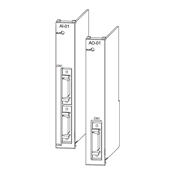
Page 22: Module Specifications
2 AI-01 Module 2.1.1 AI-01 Module Functions and External Dimensions 2.1 AI-01 Module Specifications This section explains the appearance, function, and specifications of AI-01 module. 2.1.1 AI-01 Module Functions and External Dimensions The AI-01 module has eight channels for analog input. Three types of analog-input ranges are available − Voltage: -10 V to +10 V, Voltage: 0 V to +10 V, Current: 0 mA to 20 mA. - Page 23 ( 2 ) Hardware Specifications Items Specifications Description I/O Module Name AI-01 Model No. JAPMC-AN2300-E Number of Channels 8 channels ((4 channels /1connector)×2) Setting of the channels 1 to 8 channels (Optional) used Between channels: non-insulated Insulation Between input connector and system power supply: photocoupler insulation...
-
Page 24: Input Characteristics
2 AI-01 Module 2.1.3 Input Characteristics 2.1.3 Input Characteristics This section explains the input characteristics table corresponding to the analog input value and voltage and current mode, and input characteristic drawings. ( 1 ) Input Characteristics and Corresponding Modes Voltage mode 1 Voltage mode 2 Current mode Analog input value... -
Page 25: Module Connections
2.2 AI-01 Module Connections 2.2 AI-01 Module Connections 2.2.1 Specifications on Cable and Connector ( 1 ) Connector Specifications Connector Model Connector No. of Connector Name Pins Module Cable Manufacturer ・Connector 10126-3000PE ・Shell Analog Input Sumitomo CN1/CN2 10226-52A3PL 10326-52A0-008 Connector 3M Limited ... -
Page 26: Connector Pin Arrangement
2 AI-01 Module 2.2.2 Connector Pin Arrangement Wire Color Dot Color Dot Mark Mark Tube Twisted-pair Wire 26-pin Terminal (Label) Orange -- Orange Black -- Pink Black - Pink - Orange - Orange Black - Note: The cable is shielded twisted-pair and connected to connector shell of CN1 by metal-clamp. 2.2.2 Connector Pin Arrangement The following table shows the connector (CN1, CN2) of the pin arrangement and the terminal layout for the AI-01 module. - Page 27 2.2 AI-01 Module Connections ( 2 ) CN2 Pin Arrangement and Terminal Layout [ a ] Pin Arrangement at Connection Side MDP5 MDN5 MDP6 MDN6 MDP7 MDN7 MDP8 MDN8 [ b ] Terminal Specifications Signal Signal Function Function Name Name Voltage input 5 MDP5...
-
Page 28: Circuit Configuration And Connection Example
2 AI-01 Module 2.2.3 Circuit Configuration and Connection Example 2.2.3 Circuit Configuration and Connection Example ( 1 ) AI-01 Module Circuit Configuration Multiplexer Voltage input 10 kΩ Current input Mode 256.5 Ω 10 kΩ Ground Voltage input 10 kΩ Current input Mode 256.5 Ω... - Page 29 2.2 AI-01 Module Connections ( 2 ) AI-01 Module Connection Example (CN1) Junction-terminal block AI-01 External device Voltage input1 Ground 1 Current input1 -10 to +10V Mode selection1 External device Voltage input 2 Ground 2 Current input 2 -10 to +10V Mode selection 2 Voltage input 3 Ground 3...
-
Page 30: Module Settings
2 AI-01 Module 2.3.1 Setting the Input Mode 2.3 AI-01 Module Settings This section describes the items to be set using the MPE720 after connecting the AI-01 Module. After connecting the AI-01 Module, use the following procedures to select the input mode, offset/gain, and self con- figuration. -
Page 31: Setting The Offset/Gain
2.3 AI-01 Module Settings 2.3.2 Setting the Offset/Gain The offset/gain settings do not usually have to be adjusted. The AI-01 Module has been adjusted before shipment so the appropriate value is input for the specified voltage or current. If more precise adjustments are required, use the follow- ing procedure to adjust the offset/gain. -
Page 32: Self Configuration
2 AI-01 Module 2.3.3 Self Configuration 2.3.3 Self Configuration The MP2300, MP2200, and MP2100M machine controllers in the MP2000-series have a self configuration function. With self configuration, the I/O leading and end registers for the AI-01 Module will be automatically allocated and all of the channels will be shown as being unused if (no channel has been selected in the AI-01 Configuration window). -
Page 33: Module
AO-01 Module This chapter explains the detailed specifications and functions, connection methods, and settings of the AI-01 Module. 3.1 AO-01 Module Specifications - - - - - - - - - - - - - - - - - - - - - - - - - - - - - - - - - 34 3.1.1 AO-01 Module Function and External dimensions - - - - - - - - - - - - - - - - - - - - - - - - - - -34 3.1.2 Specifications - - - - - - - - - - - - - - - - - - - - - - - - - - - - - - - - - - - - - - - - - - - - - - - - - - - - -34 3.1.3 Output Characteristics - - - - - - - - - - - - - - - - - - - - - - - - - - - - - - - - - - - - - - - - - - - - - - -36... -
Page 34: Module Specifications
3 AO-01 Module 3.1.1 AO-01 Module Function and External dimensions 3.1 AO-01 Module Specifications This section explains the appearance, function, and specifications of the AO-01 module. 3.1.1 AO-01 Module Function and External dimensions The AO-01 module has four channels for analog input. Two types of analog-output ranges are available − Voltage: -10 V to +10 V, Voltage: 0 V to +10 V. - Page 35 3.1 AO-01 Module Specifications Item Specifications Conforming to JIS B 3502: 10 to 57 Hz with single-amplitude of 0.075 mm Vibration 57 to 150 Hz with fixed acceleration of 9.8 m/s Resistance Mechanical 10 sweeps each in X, Y, and Z directions Operating (sweep time: 1 octave/min) Conditions...
-
Page 36: Output Characteristics
3 AO-01 Module 3.1.3 Output Characteristics 3.1.3 Output Characteristics This section explains the output characteristics table corresponding to the analog output value and voltage and current mode, and output characteristic drawings. ( 1 ) Output Characteristics Corresponding Table Output Register Analog output value Output range 1 (-10V to +10V) Output range 2 (0 to +10V) -
Page 37: Module Connections
3.2 AO-01 Module Connections 3.2 AO-01 Module Connections 3.2.1 Specifications on Cable and Connector ( 1 ) Connector Specifications Connector Model Connector No. of Connector Name Pins Module Cable Manufacturer ・Connector 10120-3000PE ・Shell Analog Output Sumitomo 10220-52A3PL 10320-52A0-008 Connector 3M Limited ... -
Page 38: Connector Pin Arrangement
3 AO-01 Module 3.2.2 Connector Pin Arrangement 3.2.2 Connector Pin Arrangement The following table shows the connector (CN1) of the pin arrangement and the terminal layout for the AO-01 module. ( 1 ) CN1 Pin Arrangement and Terminal Layout Pin Arrangement at Connection Side N.C. -
Page 39: Module Connection Example (Cn1)
3.2 AO-01 Module Connections 3.2.3 AO-01 Module Connection Example (CN1) AO-01 Junction-terminal block External device Voltage output 1 Ground 1 -10 to +10V External device Voltage output 2 Ground 2 -10 to +10V External device Voltage output 3 Ground 3 -10 to +10V External device Voltage... -
Page 40: Module Settings
3 AO-01 Module 3.3.1 Setting the Output Range 3.3 AO-01 Module Settings This section describes the items to be set using the MPE720 after connecting the AO-01 Module. After connecting the AO-01 Module, use the following procedures to select the input mode, offset/gain, and self con- figuration. -
Page 41: Setting The Offset/Gain
3.3 AO-01 Module Settings 3.3.2 Setting the Offset/Gain The offset/gain settings do not usually have to be adjusted. The AO-01 Module has been adjusted before shipment so the appropriate value is input for the specified voltage or current. If more precise adjustments are required, use the fol- lowing procedure to adjust the offset/gain. -
Page 42: Self Configuration
3 AO-01 Module 3.3.3 Self Configuration Click the OK button to save the gain, and the dialog box will close. Offset default: 0000, Gain default: 1,000. 3.3.3 Self Configuration The MP2300, MP2200, and MP2100M machine controllers in the MP2000-series have a self configuration function. With self configuration, the I/O leading and end registers for the AO-01 Module will be automatically allocated and all of the channels will be shown as being unused if (no channel has been selected in the AO-01 Configuration window). - Page 43 Index INDEX - - - - mounting/removing optional modules on machine controller - - - - - - - - - - - - - - - - - - - - - - - - - - - - - optional cover - - - - - - - - - - - - - - - - - - - - - - - - - - - - - AI-01 module...
-
Page 44: Revision History
Revision History The revision dates and numbers of the revised manuals are given on the bottom of the back cover. MANUAL NO. SIEP C880700 26A September 2009 05-8 1 -1 Published in Japan WEB revision number Date of Revision number publication Date of original publication Date of... - Page 45 Phone 81-4-2962-5151 Fax 81-4-2962-6138 YASKAWA AMERICA, INC. 2121 Norman Drive South, Waukegan, IL 60085, U.S.A. Phone (800) YASKAWA (800-927-5292) or 1-847-887-7000 Fax 1-847-887-7310 YASKAWA ELETRICO DO BRASIL LTDA. Avenida Fagundes Filho, 620 Sao Paulo-SP CEP 04304-000, Brazil Phone 55-11-3585-1100 Fax 55-11-5581-8795 YASKAWA EUROPE GmbH Hauptstraβe 185, Eschborn 65760, Germany...
Need help?
Do you have a question about the JAPMC-AN2300-E and is the answer not in the manual?
Questions and answers