Table of Contents
Advertisement
Quick Links
This .pdf document is bookmarked
Operation and Maintenance Instructions
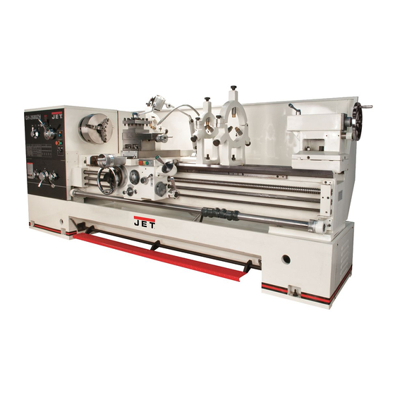
ZH Series Large Bore Lathes
Models GH-2680ZH; GH-26120ZH
Model GH-2680ZH shown
For ZH-Series Lathes Parts List and Electrical Diagrams, see document M-321860-1
JET
427 New Sanford Road
LaVergne, Tennessee 37086
Part No. M-321860
Ph.: 800-274-6848
Revision C3 08/2018
www.jettools.com
Copyright © 2017 JET
Advertisement
Chapters
Table of Contents

Related Manuals for Jet ZH Series


Summary of Contents for Jet ZH Series
- Page 1 This .pdf document is bookmarked Operation and Maintenance Instructions ZH Series Large Bore Lathes Models GH-2680ZH; GH-26120ZH Model GH-2680ZH shown For ZH-Series Lathes Parts List and Electrical Diagrams, see document M-321860-1 427 New Sanford Road LaVergne, Tennessee 37086 Part No. M-321860 Ph.: 800-274-6848...
-
Page 2: Important Safety Instructions
Do not use this lathe for other than its intended around, carrying on a conversation and “horse- use. If used for other purposes, JET disclaims play” are careless acts that can result in serious any real or implied warranty and holds itself injury. - Page 3 31. Workpieces longer than 3 times the chucking WARNING: Some dust, fumes and gases diameter must be supported by the tailstock or a created by power sanding, sawing, grinding, steady rest. drilling, welding and other construction activities 32. Avoid small chuck diameters with large turning contain chemicals known to the State of California diameters.
-
Page 4: Warranty And Service
JET sells through distributors only. The specifications listed in JET printed materials and on official JET website are given as general information and are not binding. JET reserves the right to effect at any time, without prior notice, those alterations to parts, fittings, and accessory equipment which they may deem necessary for any reason ®... -
Page 5: Table Of Contents
13.15 Shear Pin Replacement ........................27 13.16 Steady Rest Adjustment ........................27 13.17 Follow Rest Adjustment ........................28 14.0 Troubleshooting the ZH Series Lathes ....................... 29 15.0 Lubrication Schedule and General Maintenance ..................30 16.0 Reference Tables ............................31 16.1Inch Lead And Feed ..........................31 16.2Special Inch Lead And Feed ........................ -
Page 6: Specifications
4.0 Specifications Model Number................GH-2680ZH ......... GH-26120ZH Stock Number ..................321860 ..........321890 General Capacities: Maximum Swing over Bed ............26” (660mm) ......... 26” (660mm) Maximum Swing over Cross Slide ........16-1/2” (420mm) ........16-1/2” (420mm) Maximum Swing Through Gap ..........34” (870mm) ......... 34” (870mm) Length of Gap ................ - Page 7 The specifications in this manual were current at time of publication, but because of our policy of continuous improvement, JET reserves the right to change specifications at any time and without prior notice, without incurring obligations.
-
Page 8: Dimensions And Mounting Hole Centers
5.0 Dimensions and mounting hole centers Figure 1 80 inch 120 inch Lathe Size (GH-2680ZH) (GH-26120ZH) 2560mm(100.8 in.) 3565mm(140.4 in.) 3500mm(137.60 in. ) 4500mm (177.2 in.) 1721.5mm (67.8 in) Table 1... -
Page 9: General Description And Nomenclature
6.0 General description and nomenclature Figure 2 – General Description (GH-2680ZH shown) Feed Gearbox The ZH series lathe operates on a centralized gear system. The motor power is transferred through The gearbox (E) is made from high quality cast iron four v-belts to a shaft, which in turn transmits the and is mounted to the left side of the machine bed. - Page 10 T-slotted and mounted on the cross slide, can be rotated 360°, allowing tapers to be turned. The ZH series lathes are provided with small and The compound rest travels on dovetailed ways, large steady rests (T). A steady rest serves as a with adjustable gibs.
-
Page 11: Unpacking
Round Nut Spanner, 170-210 mm – E Change Gears – 63T, 69T, 78T, 90T – F NOTE: Optional accessories are available for JET Lathes, such as Taper Attachment, Collet Closer and Digital Read Out. Contact your dealer or JET for more information. -
Page 12: Installation
8.1 Leveling the lathe 8.0 Installation It is imperative that the lathe be on a level plane; that is, where headstock and tailstock center points Finish removing all crate material from around remain aligned throughout the tailstock travel, with lathe. the bed ways absent of twist and thus parallel to Unbolt lathe from shipping pallet. -
Page 13: Chuck Preparation
8.3 Chuck Preparation Lift the chuck up to the spindle nose and press onto the spindle. Tighten in place by turning Read understand the camlocks 1/4 turn clockwise. The index directions for chuck preparation. Failure to mark (A, Figure 7) on the camlock should be comply may cause serious injury and/or between the two indicator arrows (B) when damage to the lathe. -
Page 14: Maintenance/Lubrication
Failure to comply may cause serious damage to the lathe. The ZH series lathe is shipped with oil in the reservoirs. Coolant is not included. Use clean lubricants and check levels often, including before each working shift. - Page 15 through various oil lines to lubricate the ways below the saddle. Perform this several times daily. Threading Dial – Frequently lubricate via one ball oiler (P, Figure 11) on top of the dial with SAE 20W oil. Cross Slide – Daily lubricate one ball oiler on the handwheel housing (L, Figure 11)and three ball oilers on the platform (K, Figure 12), with SAE 20W oil.
-
Page 16: Coolant Preparation
GH-26120ZH: Pour coolant (approx. four gallons) into one of the chip trays (Figure 16). Or, slide out one of the chip trays and pour directly into the side trough on the center stand. After machine has been connected to power, turn on coolant pump and check to see that coolant is cycling properly. -
Page 17: Conversion To 460 Volt Operation
pump junction box according to diagram on the junction box cover. GH-26120ZH: 1) Remove top panel inside the bed (Figure 19). 2) Remove rear panel on center stand then remove the two socket head screws (Figure 20) that secure the plate on which the coolant pump is mounted. -
Page 18: Basic Controls
NOTE: Lathe will still have power. Twist button clockwise to reset. • ON Button (C, Figure 22 and 23). Activates motor. • Coolant On-Off Switch (D, Figure 22). Activates coolant pump. Speed Selection Levers (E, Figure 22): Located on front of headstock. Move levers left or right to desired spindle speed, according to accompanying chart on the dial. - Page 19 I/II/III/IV = The leadscrew is used to cut thread forms. A/B/C/D = The feed rodis used to control the feed/revolution. The ratios between them are: I: II: III: IV: = A:B:C:D = 1:2:4:8 Figure 25 Spindle Direction Control Lever (M, Figure 24).
-
Page 20: Operation
21. Travel Setting Rod (Y, Figure 27): Up to six pre-set configurations possible repetitive operations, without having to re- position the stops each time. Use the knurled knob at the right end of the rod to set the rod at one of six positions shown on the dial. Then move the desired number of eccentric stops into position for that particular operation and tighten them securely to the rod with the... -
Page 21: Tool Setup
the point of the tailstock center as a gauge and shims under the tool to obtain the correct center height. Use a minimum of two clamping screws to secure each tool. 12.2 Spindle Speed Twelve speeds are available by placing the first speed lever (E , Figure 31) in one of four positions, and placing second lever (E... -
Page 22: Thread Cutting
12.4 Thread Cutting 13.0 Adjustments Threading is performed in multiple passes, with an initial cutting depth of about 0.2 mm, and Adjustments lathe, decreasing depth in succeeding cuts. It is especially those involving alignments recommended that test cuts be made on scrap bearings, spindle, leadscrew,... -
Page 23: Tailstock Adjustments
Alternately loosen and tighten front and rear screws (C). (only front screw shown.) The scale (D) on the end of the tailstock indicates amount of offset, and helps when re-centering. Figure 35– Saddle sliding plate adjustment Figure 38 – Tailstock adjustments If the clamping force needs to be adjusted, use the hex nut (E, Figure 39). -
Page 24: Belt Adjustment And Replacement
Figure 40 – Gap section Figure 41 – Belt and brake strap adjustment To reinstall the gap section: 13.6 Brake Strap Clean the bottom and the ends of the gap section thoroughly. After the clutch is disengaged, the main drive can be stopped by the brake. -
Page 25: Aligning Tailstock To Headstock
Figure 43 – Spindle Clutch Adjustment Figure 44 – Tailstock/Headstock alignment 13.9 Spindle Bearings Make sure the lathe is OFF at the master switch. The spindle system is supported by three bearings, with the rear bearing serving as an auxiliary Remove the top cover of the headstock. -
Page 26: Lead Screw
Figure 46 – Speed control chain adjustment 13.11 Lead Screw To ensure the pitch accuracy in cutting threads, any axial run-out of the lead screw must be eliminated. See Figure 47. This is achieved by adjusting the thrust bearings (2 and 3) using the nut (1). -
Page 27: Cross Slide Nut Adjustment
Figure 50 – Cross slide nut adjustment 13.15 Shear Pin Replacement The lead screw and feed shaft are equipped with shear pins, which are designed to break in order to protect the drive system against overload. A broken shear pin must be replaced. Knock out the broken pin;... -
Page 28: Follow Rest Adjustment
13.17 Follow Rest Adjustment The follow rest mounts to the saddle with two socket head cap bolts. The follow rest should be mounted so that the locking knobs point away from the chuck. The sliding fingers are set similar to those on the steady rest –... -
Page 29: Troubleshooting The Zh Series Lathes
14.0 Troubleshooting the ZH Series Lathes Table 2 Trouble Probable Cause Remedy Verify incoming power, main leads, main No electrical power, or wiring incorrect. switch is on. Emergency stop switch is pressed. Rotate switch clockwise to release. End gear cover open, limit switch Close cover. -
Page 30: Lubrication Schedule And General Maintenance
Regularly scheduled maintenance is crucial to ensure a long service life for your machine. The schedule below shows general cleaning, lubrication points and coolant replacement information for the ZH Series Lathes. Push stop button and power off before lubricating. Follow local regulations for disposal of used coolant/lubricants. Minimize direct skin contact with lubricants and coolants, and wear eye protection when pouring coolant in case of splash. -
Page 31: Reference Tables
16.0 Reference Tables 16.1Inch Lead And Feed Table 4 T H R E A D I N G C H A R T 1.00 3.00 8.00 1.25 3.50 9.00 1.50 4.00 10.00 1.75 4.50 11.00 2.00 5.00 12.00 2.25 5.50 14.00 2.50 6.00... -
Page 32: Special Inch Lead And Feed
T H R E A D I N G C H A R T 0.50 1.75 3.00 5.50 0.75 2.00 3.50 6.00 1.00 2.25 4.00 7.00 1.25 2.50 4.50 1.50 2.75 5.00 T H R E A D I N G C H A R T 16.2Special Inch Lead And Feed Table 5 ALTERNATIVE GEAR CHANGES... -
Page 33: Speed Selection Lever Positions
16.3 Speed Selection Lever Positions Table 6 Lever Position Spindle Speeds (RPM) black black light light grey grey grey grey 1200 1600 17.0 Electrical – 230 volt to 460 volt Conversion Figure 53... -
Page 34: Change Gear Diagram
18.0 Change Gear Diagram Figure 54... - Page 35 This page intentionally left blank.
- Page 36 This page intentionally left blank. 427 New Sanford Road LaVergne, Tennessee 37086 Phone: 800-274-6848 www.jettools.com...
- Page 37 This .pdf document is bookmarked Parts List and Electrical Diagrams ZH Series Lathes Models GH-2680ZH; GH-26120ZH Model GH-2680ZH shown For ZH-Series Lathes Operation and Maintenance Instructions, see document M-321860 427 New Sanford Road LaVergne, Tennessee 37086 Part No. M-321860-1 Ph.: 800-274-6848 Revision E 10/2017 www.jettools.com...
- Page 38 JET sells through distributors only. The specifications listed in JET printed materials and on official JET website are given as general information and are not binding. JET reserves the right to effect at any time, without prior notice, those alterations to parts, fittings, and accessory equipment which they may deem necessary for any reason ®...
- Page 39 Table of Contents 1.1 Bed Assembly I – Exploded View....................... 4 1.2 Bed Assembly I (for 120” ZH only) – Exploded View ................. 5 1.3 Bed Assembly I – Parts List ....................... 6 2.1 Bed Assembly II – Exploded View...................... 8 2.2 Bed Assembly II (for 120”...
-
Page 40: Bed Assembly I - Exploded View
1.1 Bed Assembly I – Exploded View... -
Page 41: Bed Assembly I (For 120" Zh Only) - Exploded View
1.2 Bed Assembly I (for 120” ZH only) – Exploded View... -
Page 42: Bed Assembly I - Parts List
1.3 Bed Assembly I – Parts List Index No. Part No. Description Size 1 ....C6266C12701C-G ... Splash Guard (for 80” ZH only) ......80” ....... 1 ....C6266C12701D-G ... Traveling Splash Guard (for 120” ZH only) ..120” ......1 .... - Page 43 Index No. Part No. Description Size 41 ..... GB70-M10x85 ..Hex Socket Cap Screw ........M10x85 ....... 2 42 ..... C6266C01103 ..Gap ......................1 43 ..... GB118-16x60 ... Taper Pin .............. 16x60 mm ....2 44 ..... GB70-M16x50 ..Hex Socket Cap Screw ........M16x50 ....... 4 49 .....
-
Page 44: Bed Assembly Ii - Exploded View
2.1 Bed Assembly II – Exploded View... -
Page 45: Bed Assembly Ii (For 120" Zh Only) - Exploded View
2.2 Bed Assembly II (for 120” ZH only) – Exploded View... -
Page 46: Bed Assembly Ii - Parts List
39 ..... C61321723A-G ..Bracket ..................... 1 40 ..... GB70- M8x12 ... Hex Socket Cap Screw ........M8x12 ......2 41 ..... JET-165 ....JET LOGO (serial #160415ZH0145 and higher) ........1 42 ..... C6266C18305-1 ..Motor Label (serial #160315ZH0144 and lower) ........1 .... - Page 47 Index No. Part No. Description Size 45 ..... GH-1440A18304-G .. Wiring Box Cover ..................1 46 ..... GB818-M6x8 .... Cross Head Screw ..........M6x8 ......2 47 ..... C613618302 .... Warning Label ..................1 48 ..... GB2672-M6x20 ..Screw ..............M6x20 ......2...
-
Page 48: Headstock Assembly I - Exploded View
3.1 Headstock Assembly I – Exploded View ZⅠ ZⅡ Ⅰ Ⅱb Ⅳ Ⅱ Ⅲ Ⅴ Ⅶb ZⅡ Ⅵ Ⅶ... -
Page 49: Headstock Assembly I - Parts List
3.2 Headstock Assembly I – Parts List Index No. Part No. Description Size 1 ....C6266C02502-G ..Headstock Cover ..................1 3 ....C6140W02835 ..Flat Head Countersunk Screw ..............1 4 ....TS-1505051 ..... Hex Socket Cap Screw ........M10x35 ....... 8 5 .... - Page 50 Index No. Part No. Description Size 47 ..... GB1099-6x22 ... Woodruff Key ............6x22 mm ..... 1 48 ..... C6266C02763 ..Shaft ......................1 49 ..... G51-2A-25x2.4 ..O-Ring ..............25x2.4 mm ....2 50 ..... C6140W02127 ..Collar ......................2 51 .....
-
Page 51: Headstock Assembly Ii - Exploded View
4.1 Headstock Assembly II – Exploded View... -
Page 52: Headstock Assembly Ii - Parts List
4.2 Headstock Assembly II – Parts List Index No. Part No. Description Size 1 ....C6266CHA01 ... Chain ..............12.7 x 58 mm ....1 2 ....GB894.1-16 ....C-Clip for Shaft ............ 16 mm ......1 3 ....C6140W02808 ..Chain Wheel..................... 2 4 .... - Page 53 Index No. Part No. Description Size 52 ..... C6140W02822-G ..Lever ......................1 53 ..... C6266C02115-G ..Lever Support ..................1 54 ..... GB73-M12x14 ..Set Screws ............M12x14 ....... 1 55 ..... C6266C02774 ..Bolt ......................1 56 .....
-
Page 54: Headstock Assembly Iii - Exploded View
5.1 Headstock Assembly III – Exploded View... -
Page 55: Headstock Assembly Iii - Parts List
5.2 Headstock Assembly III – Parts List Index No. Part No. Description Size 1 ....C6266C08501-G ..Back Cover....................1 2 ....GB2672-M6x25 ..Screw ..............M6x25 ......3 3 ....C6266C08706 ..Upper Hinge ..................... 2 4 ....GB70-M6x12 .... Hex Socket Cap Screw ........M6x12 ......8 5 .... -
Page 56: Headstock Assembly Iv - Exploded View
6.1 Headstock Assembly IV – Exploded View Ⅳ Ⅰ Ⅱ Ⅴ Ⅱb Ⅲ... -
Page 57: Headstock Assembly Iv - Parts List
6.2 Headstock Assembly IV – Parts List Index No. Part No. Description Size 1 ....C6140W02752-1/2 ... Round Nut ....................1 2 ....TS-1523011 ..... Hex Socket Set Screw ......... M6x6 ......1 3 ....C6140W02752-2/2 ... Clamping Piece ..................1 4 .... - Page 58 Index No. Part No. Description Size 57 ..... GB3452.1-25x2.65 ... O-Ring ..............25x2.65 mm ....1 58 ..... C6266C02729 ..Shaft (IIb) ....................1 59 ..... GB893.1-47 ....C-Clip ..............47 mm ......2 60 ..... BB-6005 ....Ball Bearing ............6005 ......2 61 .....
-
Page 59: Headstock Assembly V - Exploded View
7.1 Headstock Assembly V – Exploded View Ⅵ Ⅶb Ⅶ... -
Page 60: Headstock Assembly V - Parts List
7.2 Headstock Assembly V – Parts List Index No. Part No. Description Size 1 ....TS-1505031 ..... Hex Socket Cap Screw ........M10x25 ....... 1 2 ....C6266C02108 ..Back Flange Cover .................. 1 3 ....GB119-6x8 ....Pin ................ 6x8 ......1 4 .... -
Page 61: Gear Assembly - Exploded View
8.1 Gear Assembly – Exploded View 8.2 Gear Assembly – Parts List Index No. Part No. Description Size 1 ....C6266C08708-G ..Splash Guard ................... 1 2 ....GB818-M6x8 .... Screw (serial #160315ZH0144 and lower) ..M6x8 ......2 .... -
Page 62: Gear Box Assembly I - Exploded View
9.1 Gear Box Assembly I – Exploded View Ⅰ Ⅱ Ⅲ... -
Page 63: Gear Box Assembly I - Parts List
9.2 Gear Box Assembly I – Parts List Index No. Part No. Description Size 1 ....C6266C05767-G ..Oil Plate ....................1 2 ....TS-1534032 ..... Cross Recessed Pan Head Screw ...... M6x10 ....... 12 2a ..... GB70-M3x10 .... Hex Socket Cap Screw ........M3x10 ......6 3 .... -
Page 64: Gear Box Assembly Ii - Exploded View
10.1 Gear Box Assembly II – Exploded View... -
Page 65: Gear Box Assembly Ii - Parts List
10.2 Gear Box Assembly II – Parts List Index No. Part No. Description Size 1 ....C6140W05109 ..Sliding Block..................... 7 2 ....C6140W05A701 ..Shaft ......................2 3 ....C6140W05A105 ..Ratio Change Rocker ................1 4 .... - Page 66 Index No. Part No. Description Size 58 ..... C6140W05715-G ..Cover ......................1 59 ..... C6140W05A724 ..Positioning Disc ..................1 60 ..... C6140W05A104-G ... Lever Support ..................1 61 .... C6140W05308 ..Handle Panel (serial #160315ZH0144 and lower) ........1 ....
-
Page 67: Gear Box Assembly Iii - Exploded View
11.1 Gear Box Assembly III – Exploded View... -
Page 68: Gear Box Assembly Iii - Parts List
11.2 Gear Box Assembly III – Parts List Index No. Part No. Description Size 3 ....C6140W05A730 ..Shaft (I) ....................1 4 ....C6266C05772J ..Bearing Cover ..................1 5 ....G51-1-.B-35x50x8 ..Oil Seal ..............B-35x50x8 ....2 6 .... - Page 69 Index No. Part No. Description Size 58 ..... C6140W05A744 ..Sleeve ...................... 1 59 ..... C6140W05A121-G ... Flange Sleeve ..................1 60 ..... G51-1-B-25x40x7 ..Oil Seal ..............B-25x40x7 ....1 61 ..... C6140W05768 ..Shaft Connector ..................1 62 .....
-
Page 70: Brake Assembly - Exploded View
12.1 Brake Assembly – Exploded View... -
Page 71: Brake Assembly - Parts List
12.2 Brake Assembly – Parts List Index No. Part No. Description Size 1 ....C6266C22705 ..Brake Belt ....................1 2 ....GB70-M6x8 ....Hex Socket Cap Screw ........M6x8 ......4 5 ....C6266C22704 ..Bolt ......................1 6 .... -
Page 72: Saddle And Cross Slide Assembly - Exploded View
13.1 Saddle and Cross Slide Assembly – Exploded View... -
Page 73: Saddle And Cross Slide Assembly - Parts List
13.2 Saddle and Cross Slide Assembly – Parts List Index No. Part No. Description Size 1 ....C6266C04101A-G ... Slide ......................1 2 ....GB73-M10x16 ..Slotted Set Screw ..........M10x16 ....... 1 3 ....C614W04503 ... Wipe Plate ....................1 4 .... - Page 74 Index No. Part No. Description Size ....C6266C04109 ..Sleeve (serial #111105ZH0006 and higher) ..........1 50 ..... GB1099-5x7.5x19 ..Woodruff Key ............5x7.5x19 mm ....1 51 ..... C6266C04726J ..Shaft ......................1 52 ..... GB117-4x35 ..... Taper Pin .............. 4x35 mm ..... 1 53 .....
-
Page 75: Tool Post And Compound Rest Assembly - Exploded View
14.1 Tool Post and Compound Rest Assembly – Exploded View... -
Page 76: Tool Post And Compound Rest Assembly - Parts List
14.2 Tool Post and Compound Rest Assembly – Parts List Index No. Part No. Description Size 1 ....C6266C04104 ..Revolving Plate ..................1 2 ....TS-1540081 ..... Hex Nut ..............M12 ......4 3 ....C6266C04706 ..Compound Screw ..................4 4 .... -
Page 77: Apron Assembly I - Exploded View
15.1 Apron Assembly I – Exploded View Ⅵ Ⅴ Ⅶ Ⅲ Ⅹ Ⅰ Ⅱ Ⅹ Ⅱ Ⅳ Ⅹ Ⅲ Ⅰ Ⅹ Ⅸ Ⅷ... -
Page 78: Apron Assembly I - Parts List
15.2 Apron Assembly I – Parts List Index No. Part No. Description Size 1 ....C6266C06101-G ..Apron Casting ..................1 2 ....TS-1524021 ..... Socket Set Screw ..........M8x10 ......2 3 ....C6266C06506 ..Gasket ...................... 1 4 .... - Page 79 Index No. Part No. Description Size 62 ..... SB-5MM ....Steel Ball .............. 5 mm ......4 63 ..... C6266C06715 ..Oil Purifier ....................1 64 ..... C6266C06107-G ..Pump ......................1 65 ..... GB65-M6x12 .... Slotted Socket Cap Screw ........M6x12 ......3 66 .....
-
Page 80: Apron Assembly Ii - Exploded View
16.1 Apron Assembly II – Exploded View Ⅶ Ⅸ Ⅹ Ⅻ Ⅺ Ⅹ Ⅲ... -
Page 81: Apron Assembly Ii - Parts List
16.2 Apron Assembly II – Parts List Index No. Part No. Description Size 1 ....C6140W06738 ..Cap ......................1 2 ....GB6172-M12 .... Hex Flat Nut ............M12 ......1 3 ....GB78-M12x60 ..Hex Set Screw (serial #130531ZH0069 and lower) ............ - Page 82 Index No. Part No. Description Size 50 ..... GB67-M6x8 ....Slotted Pan Head Screw ........M6x8 ......3 51 ..... C6140W06701 ..Pin ......................3 52 ..... Q81-1-1.6x8x22 ..Spring ..............1.6x8x22 ..... 3 53 ..... C6140W06713 ..Fork ......................1 54 .....
-
Page 83: Apron Assembly Iii - Exploded View
17.1 Apron Assembly III – Exploded View Ⅵ Ⅳ Ⅲ Ⅴ Ⅱ Ⅰ... -
Page 84: Apron Assembly Iii - Parts List
17.2 Apron Assembly III – Parts List Index No. Part No. Description Size 1 ....C6140W06751 ..Gear ......................1 2 ....GB71-M6x8 ....Slotted Set Screw ..........M6x8 ......2 3 ....C6140W06309 ..Sleeve ...................... 1 4 .... -
Page 85: Apron Assembly Iv - Exploded View
18.1 Apron Assembly IV – Exploded View... -
Page 86: Apron Assembly Iv - Parts List
18.2 Apron Assembly IV – Parts List Index No. Part No. Description Size 1 ....GB1155-10 ....Oil Cup ..............10 mm ......1 2 ....C6266C11703 ..Handle ...................... 1 3 ....C6266C11305 (in) ..Label (serial #160315ZH0144 and lower) ..........1 .... -
Page 87: Tailstock Assembly I - Exploded View
19.1 Tailstock Assembly I – Exploded View... -
Page 88: Tailstock Assembly I - Parts List
19.2 Tailstock Assembly I – Parts List Index No. Part No. Description Size 1 ....1440R03105 .... Nut ......................1 2 ....TS-1504041 ..... Hex Socket Cap Screw ........M8x20 ......7 3 ....1860R03710A ..Lead Screw ....................1 4 .... -
Page 89: Tailstock Assembly Ii - Exploded View
20.1 Tailstock Assembly II – Exploded View... -
Page 90: Tailstock Assembly Ii - Parts List
20.2 Tailstock Assembly II – Parts List Index No. Part No. Description Size 1 ....C6140W03110 ..Nut ......................1 2 ....GB6171-M20x1.5 ..Hex Nut ..............M20x1.5 ...... 1 3 ....TS-1550111 ..... Flat Washer ............20 mm ......1 4 .... -
Page 91: Steady Rest Assembly (Small And Large) - Exploded View
21.1 Steady Rest Assembly (Small and Large) – Exploded View... -
Page 92: Steady Rest Assembly (Small) - Parts List
21.2 Steady Rest Assembly (Small) – Parts List Index No. Part No. Description Size ....GH-26XX-SRA ..Steady Rest Assembly–Small (includes #1-19) ......... 1 ....GB4141.29-X12 ..A Type Asterisk Handle ........Ø12 mm ...... 3 2 ....C6140W10702 ..Sliding Sleeve ..................3 3 .... -
Page 93: Follow Rest Assembly - Exploded View
22.1 Follow Rest Assembly – Exploded View 22.2 Follow Rest Assembly – Parts List Index No. Part No. Description Size 1 ....GB4141.29-12 ..A-Type Knurled Handle ........12 mm ......1 2 ....GB117-4x25 ..... Pin ................ 4x25 mm ..... 1 3 .... -
Page 94: Coolant And Work Light Assembly - Exploded View
23.1 Coolant and Work Light Assembly – Exploded View 23.2 Coolant and Work Light Assembly – Parts List Index No. Part No. Description Size 1 ....RT-001C ....Rubber Tube (for 80” ZH only) ......ID 1/2" x 2280 ..... 1 .... -
Page 95: Travel Stop Assembly - Exploded View
24.1 Travel Stop Assembly – Exploded View... -
Page 96: Travel Stop Assembly - Parts List
24.2 Travel Stop Assembly – Parts List Index No. Part No. Description Size 1 ....C6266C26A102-G ... Left Support....................1 2 ....GB118-8x40 ..... Pin ................ 8x40 mm ..... 4 3 ....TS-1504081 ..... Hex Socket Head Cap Screw ......M10x40 ....... 4 3a ..... -
Page 97: Small Carriage Stop - Exploded View
25.1 Small Carriage Stop – Exploded View 25.2 Small Carriage Stop – Parts List Index No. Part No. Description Size 1 ....TS-1492031 ..... Hex Cap Screw ............ M12x35 ....... 2 2 ....C6266C01112 ..Clamping Plate ..................1 3 .... -
Page 98: Toolbox, Accessories, And Attachments
25 ..... ZX-OP-15 ....Cross Point Screw Driver * ..............1 26 ..........Open End Wrench Set * ........17-19, 19-22 ....1 27 ..... ZX-OP-10 ....Touchup Paint Can (JET Gray) * ............. 1 28 ..... ZX-OP-09 ....Oil Gun * ....................1 29 ..... -
Page 99: Electrical Components
27.1 Electrical Components FR2–FR3 KM1 KM2, KM3 QF1-QF4 5 KA1... -
Page 100: Electrical Diagram
27.2 Electrical Diagram... -
Page 101: Electrical Components - Parts List
27.3 Electrical Components – Parts List Index No. Part No. Description Model Size M1....Y132M-4TH/B3 ..Main Motor ....Y132M-4TH/B3 ..10HP, 3PH, 230/460V ..1 M2 ....ZX-CW04 ....Coolant Pump (serial #141020ZH0102 and lower) ..........................AB-12TH ....1/8HP, 3PH, 230/460V ..1 ..... -
Page 102: Chuck Guard Assembl - Exploded View Y
28.1 Chuck Guard Assembl – Exploded View y 28.2 Chuck Guard Assembly – Parts List Index No. Part No. Description Size 1 ....GH1640ZX19701 ..Protection Guard (serial #160315ZH0144 and lower) ......1 ....GH1640ZX19701A ... Protection Guard (serial #160415ZH0145 and higher) ......1 2 .... -
Page 103: Carriage Lubrication - Exploded View
29.1 Carriage Lubrication – Exploded View 29.2 Carriage Lubrication– Parts List Index No. Part No. Description Size 1 ..GB2089-1x8x30 .... Spring ..............1x8x30 mm ....2 2 ..........Nylon Pipe ............Ø 6x1 mm ....4 3 ..CB-6 ......Vitta Tie-in ............M10x1 ......4 4 .. -
Page 104: Ordering Replacement Parts
Non-proprietary parts, such as fasteners, can be found at local hardware stores, or may be ordered from JET. Some parts are shown for reference only, and may not be available individually.
Need help?
Do you have a question about the ZH Series and is the answer not in the manual?
Questions and answers