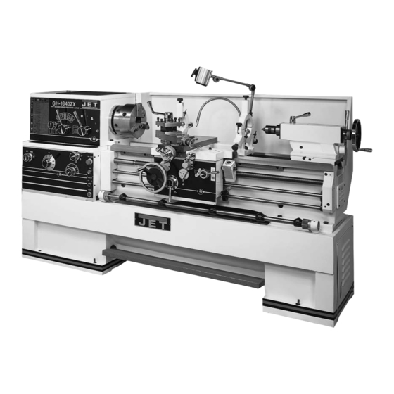
Jet GH-1440ZX Operating Instructions Manual

Jet GH-1440ZX Operating Instructions Manual

Zx series
Hide thumbs Also See for GH-1440ZX:

Advertisement

Models GH-1440ZX/1440ZX-EVS/1460ZX
GH-1640ZX/1660ZX
GH-1840ZX/1860ZX/1880ZX
GH-2280ZX
WMH TOOL GROUP, Inc.
427 New Sanford Road
LaVergne, TN 37086
Ph.: 800-274-6848
www.jettools.com

Operating Instructions

ZX Series Lathes
Part No. M-321910
Revision H 05/09
Copyright © 2009 WMH Tool Group, Inc.

Advertisement

Table of Contents
loading

Summary of Contents for Jet GH-1440ZX

  • Page 1: Operating Instructions

    Operating Instructions ZX Series Lathes Models GH-1440ZX/1440ZX-EVS/1460ZX GH-1640ZX/1660ZX GH-1840ZX/1860ZX/1880ZX GH-2280ZX WMH TOOL GROUP, Inc. 427 New Sanford Road LaVergne, TN 37086 Part No. M-321910 Ph.: 800-274-6848 Revision H 05/09 www.jettools.com Copyright © 2009 WMH Tool Group, Inc.
  • Page 2: Warranty And Service

    Warranty and Service WMH Tool Group, Inc., warrants every product it sells. If one of our tools needs service or repair, one of our Authorized Service Centers located throughout the United States can give you quick service. In most cases, any of...
  • Page 3: Table Of Contents

    Table of Contents Warranty and Service ..........................2 Table of Contents ............................ 3 Warning ..............................4 Specifications – 14” Lathes ........................6 Specifications – 16” Lathes ........................7 Specifications – 18” Lathes ........................8 Specifications – 22” Lathes ........................9 Unpacking .............................
  • Page 4: Warning

    5. Do not use this lathe for other than its intended use. If used for other purposes, WMH Tool Group disclaims any real or implied warranty and holds itself harmless from any injury that may result from that use.
  • Page 5 21. Give your work undivided attention. Looking around, carrying on a conversation and “horse-play” are careless acts that can result in serious injury. 22. Maintain a balanced stance at all times so that you do not fall or lean against moving parts. Do not overreach or use excessive force to perform any machine operation.
  • Page 6: Specifications - 14" Lathes

    The following specifications were current at the time this manual was published, but because of our policy of continuous improvement, WMH Tool Group, Inc. reserves the right to change specifications at any time and without prior notice, without incurring obligations.
  • Page 7: Specifications - 16" Lathes

    Specifications – 16” Lathes Model Number ...............GH-1640ZX .......GH-1660ZX Stock Number................321930 ........321940 Capacities: Swing over Bed (in.) ................16 ..........16 Swing over Cross Slide (in.) ..............10 ..........10 Swing Through Gap (in.) ..............25-7/8 ........25-7/8 Length of Gap (in.) ................. 12-1/4 ........12-1/4 Distance between Centers (in.) ............
  • Page 8: Specifications - 18" Lathes

    Specifications – 18” Lathes Model Number ............ GH-1840ZX ....GH-1860ZX ....GH-1880ZX Stock Number............321950 ...... 321960 ..... 321970 Capacities: Swing over Bed (in.) ............18 ......18 ......18 Swing over Cross Slide (in.) ..........11 ......11 ......11 Swing Through Gap (in.) ..........
  • Page 9: Specifications - 22" Lathes

    Specifications – 22” Lathes Model Number .........................GH-2280ZX Stock Number..........................321980 Capacities: Swing over Bed (in.) ..........................22 Swing over Cross Slide (in.) ........................11 Swing Through Gap (in.) ........................27-1/2 Length of Gap (in.) ........................... 12-1/4 Distance between Centers (in.) ......................80 Headstock: Spindle Bore (in.) ..........................
  • Page 10: Unpacking

    Tool Box containing: Unpacking Open End Wrench Set Hex Wrench Set Open shipping container and check for shipping Morse Reduction Sleeve damage. Report any damage immediately to Center your distributor and shipping agent. Do not Leveling Bolts with Hex Nuts discard any shipping material until the Lathe is Leveling Pads assembled and running properly.
  • Page 11: Uncrating And Cleanup

    Uncrating and Cleanup 1. Finish removing the wooden crate from around the lathe. 2. Unbolt the lathe from the shipping crate bottom. 3. Choose a location for the lathe that is dry, has good lighting, and has enough room to allow servicing the lathe on all four sides.
  • Page 12: Lubrication

    3. Inspect the camlock studs. Make sure they have not become cracked or broken during transit. Clean all parts thoroughly with solvent. Also clean spindle camlocks. 4. Cover all chuck jaws and scroll inside the chuck with #2 lithium tube grease. Cover the spindle, camlocks, and chuck body with a light film of 20W oil.
  • Page 13: Coolant Preparation

    Drain oil completely and refill after the first three months of operation. Then, change oil in the apron annually. Pull knob (C, Figure 5) on the one-shot lube system and hold for several seconds to allow oil to fill the pump. When the knob is released, oil will flow through various oil lines to lubricate the ways and cross slide surface.
  • Page 14: Conversion To 460 Volt Operation

    The main motor is rated at 7-1/2 HP (or 10HP for model 2280ZX), 230/460V and comes from the factory prewired at 230V. Confirm that power available at the lathe’s location is the same rating as the lathe. Power is connected properly when rotating the forward-reverse knob (E, Figure 12) to the left position causes...
  • Page 15: Carriage

    Carriage The carriage (C, Figure 10) is made from high quality cast iron. The cross-slide (E, Figure 10) is mounted on the carriage and moves on a dovetailed slide which can be adjusted for play by means of the gibs. The compound slide (D, Figure 10) which is T- slotted, and mounted on the cross slide (E, Figure 10) can be rotated 360°.
  • Page 16: Follow Rest

    To set the steady rest: 1. Loosen three hex socket cap screws. 2. Loosen knurled screw and open sliding fingers until the steady rest can be moved with its fingers around the workpiece. Secure the steady rest in position. 3. Set the fingers snugly to the workpiece and secure by tightening three hex socket cap screws.
  • Page 17 4. Feed/Lead Selector Lever (H, Figure 12): Located on front of headstock. Used when setting up for threading or feeding. 5. Compound Slide (L, Figure 13) is located on top of the cross slide and can be rotated 360°. There are calibrations in degrees (M, Figure 13) below the rest to assist in placement of the compound slide to the desired angle.
  • Page 18 15. Compound Rest Traverse Handle (J, Figure 13): Located on the end of the compound slide. Rotate clockwise counterclockwise to position. 16. Tool Post Clamping Lever (K, Figure 13): Located on top of the tool post. Rotate counterclockwise to loosen and clockwise to tighten.
  • Page 19: Operation

    Operation Feed and Thread Selection 1. Reference the feed and thread chart on the front of the headstock (A, Figure 16). 2. Move levers and knobs (B/C/D/E, Figure 16) to the appropriate position according to the feed and thread chart. Thread Cutting 1.
  • Page 20: Removing Gap Section

    Removing Gap Section 1. To remove the gap section, remove four hex socket cap screws, and two hex cap bolts. 2. Tighten the hex nuts on the tapered alignment pins to loosen the pins. Once loosened, they can be removed. 3.
  • Page 21: Parts List

    Parts List ZX Series Lathes WALTER MEIER (Manufacturing) Inc. 427 New Sanford Road LaVergne, Tennessee 37086 Part No. M-321910-1 Ph.: 800-274-6848 Revision H1 08/2010 www.waltermeier.com Copyright © 2010 Walter Meier (Manufacturing) Inc.
  • Page 22 Table of Contents Table of Contents ............................ 2 Stand Assembly ........................... 3-5 Brake Assembly ........................... 6-7 Bed Assembly ............................ 8-10 Headstock Assembly I ........................11-13 Headstock Assembly II ........................14-16 Headstock Assembly III ........................17-18 Headstock Assembly IV ........................19-20 Change Gear Box Assembly I ......................
  • Page 23: Stand Assembly

    Stand Assembly...
  • Page 24 Stand Assembly Index Part Description Size Qty. 1 ..ZX-01101A ....Pulley ....................1 .... GH2280ZX-01101 ..Pulley (for 2280ZX) ................1 2 ..ZX-S2 ......Cylindrical End Set Screw ........M8x16 ......1 3 ..ZX-01734 ......Cover ....................1 .... ML-2080-01701.....Cover (for 2280ZX) ................1 4 ..
  • Page 25 Index Part Description Size Qty. 37 ..TS-1540072 ....Hex Nut ..............M10 ......4 38 ..TS-1550071 ....Flat Washer ............M10 ......4 39 ..TS-1491041 ....Hex Cap Bolt ............M10x30 ...... 4 80 ..ZX-01716A ....Stand Front Cover (for 1440/1640/1840ZX)..........1 .... ZX-01716B ....Stand Front Cover (for 1460/1660/1860ZX)..........1 ....
  • Page 26: Brake Assembly

    Brake Assembly...
  • Page 27 Brake Assembly Index Part Description Size Qty. 40 ..ZX-22101 ......Fork ....................... 1 41 ..ZX-S41 ......Spring Pin ............5x40 ......1 42 ..ZX-22703 ......Butt Nail Support ................... 1 43 ..TS-1524021 ....Socket Set Screw ..........M8x10 ......1 44 ..ZX-S44 ......Cross Head Screw ..........M5x20 ......4 45 ..
  • Page 28: Bed Assembly

    Bed Assembly...
  • Page 29 Bed Assembly Index Part Description Size Qty. 1 ..ZX-01104A ....Bed (for 1440/1640/1840ZX)..............1 .... ZX-01104B ....Bed (for 1460/1660/1860ZX)..............1 .... ZX-01104C....Bed (for 1880/2280ZX) ................1 2 ..TS-1550101 ....Flat Washer ............M16 ......8 3 ..ZX-B3 ......Hex Cap Bolt ............M16x50 ...... 8 4 ..
  • Page 30 Index Part Description Size Qty. 32 ..ZX-01108 ......Sleeve (serial # 010611ZX349 and lower) ..........1 .... ZX-01108N....New Sleeve (serial # 010618ZX350 and higher) ........1 33 ..ZX-01709A ....Feed Rod (for 40” models, serial # 010611ZX349 and lower) ....1 ....
  • Page 31: Headstock Assembly I

    Headstock Assembly I...
  • Page 32 Headstock Assembly I Index Part Description Size Qty. 1 ..ZX-02306 ......Round Sign Plate................... 3 2 ..ZX-02122 ......Positioning Handle ................. 1 3 ..ZX-H3 ......Flat End Set Screw ..........M10x12 ...... 1 4 ..ZX-H4 ......Spring ..............YI-1x8x25 ....1 5 ..ZX-H5 ......Steel Ball ............8 ......... 1 6 ..
  • Page 33 Index Part Description Size Qty. 57 ..ZX-02110 ......Bushing ....................1 58 ..ZX-02729 ......Cover ....................1 59 ..ZX-H59 ......Pin..............3n6x10 ....... 1 60 ..ZX-H6 ......Countersunk Head Screw ........M5x12 ......1 61 ..ZX-H61 ......Countersunk Head Screw ........M8x12 ......1 62 ..
  • Page 34 Headstock Assembly II...
  • Page 35: Headstock Assembly Ii

    Headstock Assembly II Index Part Description Size Qty. 95 ..ZX-02107 ......Pulley ....................1 96 ..TS-1503061 ....Socket Cap Screw ..........M6x25 ......4 97 ..ZX-02106 ......Bearing Cover ..................1 98 ..ZX-02506 ......Gasket....................1 99 ..ZX-H99 ......Ring Seal ............32x52 ......1 100 ..
  • Page 36 Index Part Description Size Qty. 143 ..ZX-H143 .......Flat Head Set Screw ...........M8x12 ......2 144 ..ZX-02755X ....Gear (for 14” models) .........2.5m31T ..... 1 .... ZX-02755X/6P ....Gear (for 16”/18”/22” models) ......2.5m22T ..... 1 145 ..ZX-H133 .......C-Clip ..............35 ....... 1 146 ..
  • Page 37 Headstock Assembly III...
  • Page 38: Headstock Assembly Iii

    Headstock Assembly III Index Part Description Size Qty. 152 ..ZX-02704 ......Spindle ....................1 153 ..ZX-H153 .......Flat Key ..............10x8x40 ..... 1 154 ..ZX-H154 .......Flat Key ..............10x8x50 ..... 1 155 ..ZX-H155 .......Flat Key ..............12x8x50 ..... 1 156 ..ZX-H156 .......Flat Key ..............14x9x50 ..... 1 157 ..
  • Page 39 Headstock Assembly IV...
  • Page 40: Headstock Assembly Iv

    Headstock Assembly IV Index Part Description Size Qty. 214 ..ZX-08302A ....Back Cover (for 14” models) ..............1 .... ZX-08302B ....Back Cover (for 16” models) ..............1 .... ZX-08302C ....Back Cover (for 18” models) ..............1 .... GH2280ZX-08301 ..Back Cover (for 22” model) ..............1 215 ..
  • Page 41: Change Gear Box Assembly I

    Change Gear Box Assembly I...
  • Page 42 Change Gear Box Assembly I Index Part Description Size Qty. 1 ..ZX-08101 ......Change Gear Box Casting ..............1 2 ..ZX-08108 ......Front Cover ................... 1 5 ..ZX-05104C ....Hand Wheel ..................1 6 ..ZX-05301C ....Sign Plate ....................1 7 ..
  • Page 43 Change Gear Box Assembly II...
  • Page 44: Change Gear Box Assembly Ii

    Change Gear Box Assembly II Index Part Description Size Qty. 3 ..ZX-08104 ......End Cover ..................... 4 4 ..ZX-08103 ......Bearing Support ..................1 19 ..ZX-08107 ......Gear ..............3m36T ......1 20 ..ZX-08105 ......Double Gear ............3.75m28T/3m30T ..1 21 ..ZX-08702 ......Shaft ..................... 1 22 ..
  • Page 45: Quick Change Gear Box I

    Quick Change Gear Box I...
  • Page 46 Quick Change Gear Box I Index Part Description Size Qty. 1 ..ZX-05153A ....Upper Cover ..................1 2 ..TS-1503071 ....Hex Socket Cap Screw ........M6x30 ......2 6 ..TS-1504031 ....Hex Socket Cap Screw ........M8x16 ...... 10 7 ..ZX-05109 ......Rear Cover .................... 1 8 ..
  • Page 47 Index Part Description Size Qty. 61 ..ZX-05114 ......Sleeve ....................1 62 ..ZX-05734 ......Lever Shaft .................... 1 63 ..ZX-05503 ......Gasket....................1 64 ..ZX-05110 ......Front Cover ................... 1 65 ..TS-1505021 ....Hex Socket Cap Screw ........M10x20 ...... 5 66 ..
  • Page 48 Quick Change Gear Box II...
  • Page 49: Quick Change Gear Box Ii

    Quick Change Gear Box II Index Part Description Size Qty. 81 ..ZX-05104 ......Middle Bearing Support ................. 2 82 ..ZX-Q82 ......Taper End Set Screw ..........M10x16 ...... 2 83 ..ZX-B23 ......C-Clip ..............20 ....... 3 84 ..ZX-Q84 ......C-Clip ..............42 ....... 5 85 ..
  • Page 50 Quick Change Gear Box III...
  • Page 51: Quick Change Gear Box Iii

    Quick Change Gear Box III Index Part Description Size Qty. 66 ..ZX-Q66 ......Taper Pin ............5x35 ......6 83 ..ZX-Q83 ......C-Clip ..............20 ....... 3 84 ..ZX-Q84 ......C-Clip ..............42 ....... 5 85 ..BB104 ......Single Row Radial Ball Bearing......20x42x12 ....5 98 ..
  • Page 52: Apron Assembly I

    Apron Assembly I...
  • Page 53 Apron Assembly I Index Part Description Size Qty. 1 ..TL06101 .......Apron Casting..................1 2 ..TL06103 .......Bottom Cover ..................1 3 ..TS-1540072 ....Hex Nut ..............M10 ......1 4 ..ZX-A4 ......Flat Head Set Screw ...........M10x70 ...... 1 5 ..TL06502 .......Cushion Cap ..................1 6 ..
  • Page 54 Index Part Description Size Qty..... TL06122N .....New Worm Support (serial # 010618ZX350 and higher) ......1 128 ..TL06720 .......Control Plate ..................1 129 ..TS-1514031 ....Hex Socket Cap Screw ........M6x20 ......4 130 ..ZX-A130 .......Taper Pin ............4x20 ......1 131 ..
  • Page 55 Apron Assembly II...
  • Page 56: Apron Assembly Ii

    Apron Assembly II Index Part Description Size Qty. 38 ..ZX-B23 ......C-Clip ..............20 ....... 1 39 ..BB-6204......Ball Bearing ............20x47x14 ....1 40 ..TL06705 .......Gear ..............2m65T ......1 41 ..ZX-A41 ......Taper Pin ............6x40 ......1 42 ..ZX-C40 ......C-Clip ..............25 ....... 1 43 ..
  • Page 57 Index Part Description Size Qty. 99 ..TL06722 .......Lever ..................... 1 100 ..ZX-A100 .......Cross Head Screw ..........M5x10 ......3 101 ..TL06117 ......Cover ....................1 102 ..ZX-A102 .......Adjusting Screw ..........M6x30 ......1 103 ..TS-1503051 ....Hex Socket Cap Screw ........M6x18 ......3 104 ..
  • Page 58 Apron Assembly III...
  • Page 59: Apron Assembly Iii

    Apron Assembly III Index Part Description Size Qty. 141 ..ZX-A141 .......Half Round Head Screw ........M6x18 ......1 142 ..ZX-11704 ......Washer ....................1 143 ..ZX-11301 ......Dial......................1 144 ..ZX-11105 ......Adjusting Washer .................. 1 145 ..ZX-11701 ......Shaft ..................... 1 146 ..
  • Page 60: Carriage Assembly

    Carriage Assembly...
  • Page 61 Carriage Assembly Index Part Description Size Qty. 1 ..ZX-04101A ....Saddle Casting ..................1 .... GH2280ZX-14101 ..Saddle Casting (for 2280ZX)..............1 2 ..ZX-04505 ......Wipe Plate ..................... 1 3 ..ZX-04504 ......Wipe Plate ..................... 1 4 ..ZX-H211 .......Countersunk Head Screw ........M5x16 ...... 11 5 ..
  • Page 62 Index Part Description Size Qty. 54 ..ZX-04707-1 ....Gear Sliding Sleeve ..........2m16T ......1 .... ZX-04707-1A ....Gear Sliding Sleeve(for 2280ZX) ............1 55 ..ZX-H10 ......Half Circle Key ............4x16 ......1 56 ..ZX-04751 ......Flat Key ....................1 57 ..ZX-04302 ......Nut Assembly ..................1 ....
  • Page 63 Micro Carriage Stop Index Part Description Size Qty. 1 ..ZX-09709 ......Dial......................1 2 ..ZX-MS2 ......Pin..............B4x8 ......1 3 ..ZX-09708 ......Axle ....................... 1 4 ..ZX-09105 ......Stop....................... 1 5 ..ZX-03302 ......Sign Plate ....................1 6 ..ZX-MS6 ......Nail..............3x8 ......2 7 ..
  • Page 64: Carriage Stop Assembly

    Carriage Stop Assembly...
  • Page 65 Carriage Stop Assembly Index Part Description Size Qty. 1 ..ZX-26101 ......Left Support ................... 1 2 ..TS-1504041 ....Hex Socket Cap Screw ........M8x20 ......4 3 ..ZX-C34 ......Taper Pin ............6x30 ......4 4 ..ZX-26704 ......Control Ring ..................1 5 ..
  • Page 66: Four Way Tool Post

    Four Way Tool Post...
  • Page 67 Four Way Tool Post Index Part Description Size Qty. 1 ..ZX-04103A ....Revolving Plate (for 14” models) ............1 .... ZX-04103B ....Revolving Plate (for 16” models) ............1 .... ZX-04103C ....Revolving Plate (for 18” models) ............1 .... GH2280ZX-04103 ..Revolving Plate (for 22” model) .............. 1 2 ..
  • Page 68: Tailstock Assembly I

    Tailstock Assembly I...
  • Page 69 Tailstock Assembly I Index Part Description Size Qty. 1 ..ZX-03711 ......Handle....................1 2 ..ZX-03717 ......Lever Support ..................1 3 ..ZX-03718 ......Washer ....................1 4 ..ZX-03719 ......Clamping Block ..................1 5 ..ZX-03720 ......Clamping Block ..................1 6 ..
  • Page 70 Tailstock Assembly II...
  • Page 71 Tailstock Assembly II Index Part Description Size Qty. 8 ..ZX-T8 ......Flat End Set Screw (except in 14” models)..M6x18 ......4 9 ..ZX-T9 ......Steel Ball (except in 14” models) ......4 ......... 4 15 ..ZX-03712 ......Rubber Washer (except in 14” models) ..........4 16 ..
  • Page 72: Steady Rest Assembly

    Steady Rest Assembly...
  • Page 73 Steady Rest Assembly Index Part Description Size Qty..... ZX-SRA14 ....Steady Rest Assembly, 14” (includes # 1-16) ............ZX-SRA16 ....Steady Rest Assembly, 16” (includes # 1-16) ............ZX-SRA18 ....Steady Rest Assembly, 18” (includes # 1-16) ............ZX-SRA22 ....Steady Rest Assembly, 22” (includes # 1-16) ........... 1 ..
  • Page 74: Follow Rest Assembly

    Follow Rest Assembly...
  • Page 75 Follow Rest Assembly Index Part Description Size Qty..... ZX-FRA14 .....Follow Rest Assembly, 14” (includes #1-7,9) ............ZX-FRA16 .....Follow Rest Assembly, 16” (includes #1-7,9) ............ZX-FRA18 .....Follow Rest Assembly, 18” (includes #1-7,9) ............ZX-FRA22 .....Follow Rest Assembly, 22” (includes #1-7,9) ..........1 ..
  • Page 76: Coolant And Work Light Assembly

    Coolant & Work Light Assembly...
  • Page 77 Coolant & Work Light Assembly Index Part Description Size Qty. 1 ..RT-001A .......Rubber Tube (for 1440/1640/1840ZX) ....ID 1/2"x1280mm ..1 .... RT-001B .......Rubber Tube (for 1460/1660/1860ZX) ....ID 1/2"x1780mm ..1 .... RT-001C .......Rubber Tube (for 1880/2280ZX) ......ID 1/2"x2280mm ..1 2 ..
  • Page 78: Other Parts

    Other Parts Index Part Description Size Qty. 1A ..ZX-OP-1A .....3-Jaw Chuck (mounted on lathe) ......10”, D1-8 ....1 1B ..ZX-OP-1B .....Chuck Wrench ..................1 2A ..ZX-OP-2A .....4-Jaw Chuck ............12”, D1-8 ....1 2B ..ZX-OP-2B .....Chuck Wrench ..................1 3 ..
  • Page 79: Electrical Cabinet

    Electrical Cabinet Index Part Description Size Qty. 1 ..ZX-SB1 ......Jog Button ............LAY3-11...... 1 2 ..ZX-SA2 ......Coolant Control Button ........LAY3-11X/2 ....1 3 ..ZX-SB2 ......Emergency Stop ..........LAY3-012S/1 ....1 4 ..ZX-HL ......Power Indicator Light ..........XD11-30/20 ....1 5 ..
  • Page 80: Wiring Diagram

    Wiring Diagram...
  • Page 81: Rotary Switch Diagram

    Rotary Switch Diagram 1..The Cord from the Wiring Board (part no. ZX-XT2) 2..The Grounding Wire from the Copper Plate (part no. ZX-XB)
  • Page 82 NOTES...
  • Page 83 NOTES...
  • Page 84 WALTER MEIER (Manufacturing) Inc. 427 New Sanford Road LaVergne, Tennessee 37086 Phone: 800-274-6848 www.waltermeier.com...

Table of Contents