
Related Manuals for Invacare Orion Series


Summary of Contents for Invacare Orion Series
- Page 1 Invacare® Orion Series METRO Orion , Orion en Scooter User Manual This manual MUST be given to the user of the product. BEFORE using this product, this manual MUST be read and saved for future reference.
- Page 2 All rights reserved. Republication, duplication or modification in whole or in part is prohibited without prior written permission from Invacare. Trademarks are identified by ™ and ®. All trademarks are owned by or licensed to Invacare Corporation or its subsidiaries unless otherwise noted.
-
Page 3: Table Of Contents
4.7 Adjusting the headrest ......27 Contents 4.8 Disengaging the seat to rotate or remove it ... 28 4.9 Adjusting the angle of the steering column . - Page 4 7 Controls system ........45 13 Service ......... 68 7.1 Electronics Protection System .
-
Page 5: General
This mobility device was designed for persons whose ability product safety notices and product recalls, contact your to walk is impaired, but who are still in terms of their Invacare representative. See addresses at the end of this eyesight and physically and mentally able to operate an document. -
Page 6: Indications
1.9 Limitation of liability 1.6 Regulations Invacare accepts no liability for damage arising from: The vehicle was successfully tested according to German and international standards as to its safety. It satisfies •... - Page 7 General • Incorrect assembly or set-up by the purchaser or a third party • Technical modifications • Unauthorised modifications and/or use of unsuitable spare parts 1603456-D...
-
Page 8: Safety
Invacare® Orion Series 2 Safety WARNING! Risk of damage or injury if mobility device is accidentally set into motion 2.1 General safety notes – Switch off the mobility device before you get in, get out or handle unwieldy objects. DANGER! –... - Page 9 Safety WARNING! CAUTION! Risk of falling out of the mobility device Risk of injury due to wrong lifting or dropping – If a posture belt is installed, it should be of heavy components correctly adjusted and used each time you use –...
-
Page 10: Safety Information On The Electrical System
Textiles and other materials that normally would mobility device that are not expressly certified not burn are easily ignited and burn with great by Invacare for this purpose. Have all electrical intensity in oxygen enriched air. installations done by your authorized Invacare –... - Page 11 Safety WARNING! WARNING! Risk of death, serious injury, or damage Risk of death or serious injury Corroded electrical components due to water or Failure to observe these warnings can cause an liquid exposure can result in death, serious injury, electrical short resulting in death, serious injury, or damage.
-
Page 12: Safety Information On Electromagnetic Interference
Invacare® Orion Series Risk of damage to the mobility device WARNING! A failure in the electric system can lead to Risk of malfunction due to electromagnetic unusual behavior such as continuous light, no interference light, or noises from the magnetic brakes. -
Page 13: Safety Information On Driving And Freewheel Mode
Safety 2.4 Safety information on driving and freewheel WARNING! mode Risk of injury if the mobility device tips over (continued) WARNING! – Never use the mobility device to transport Risk of injury if the mobility device tips over more than one person. –... - Page 14 Invacare® Orion Series WARNING! WARNING! The center of gravity of the scooter is higher Risk of tipping than that of a power wheelchair. Antitippers (stabilizers) are only effective on firm There is an increased tipping risk when ground. They sink in on soft ground such as negotiating bends.
-
Page 15: Safety Information With Regard To Care And Maintenance
Contact a provider changing mobility device users, it would be or Invacare technician. expedient to carry out intermediate checks on the brakes, accessories and running gear. – If the mobility device is to be operated on... -
Page 16: Safety Information Regarding Changes And Modifications To The Mobility Device
– Only use seating systems that have been approved by Invacare for this mobility device. Electrical and electronic components which have not been approved by Invacare for use with this mobility device can cause fire hazards and lead to electromagnetic damage. -
Page 17: Labels On The Product
– The CE marking is invalidated if components or accessories are replaced or added that have not been approved for this product by Invacare. – In this case, the company that adds or replaces the components or accessories is responsible... - Page 18 Invacare® Orion Series Explanation of symbols on labels Identification of the position of the coupling Date of manufacture lever for driving and push operation. This product complies European representative with Directive 93/42/EEC label on the chassis at the concerning medical devices.
- Page 19 Safety This product has been This symbol indicates the supplied from an “Drive” position of the environmentally aware coupling lever. In this manufacturer. This product position the motor is may contain substances that engaged and the motor could be harmful to the brakes are operational.
-
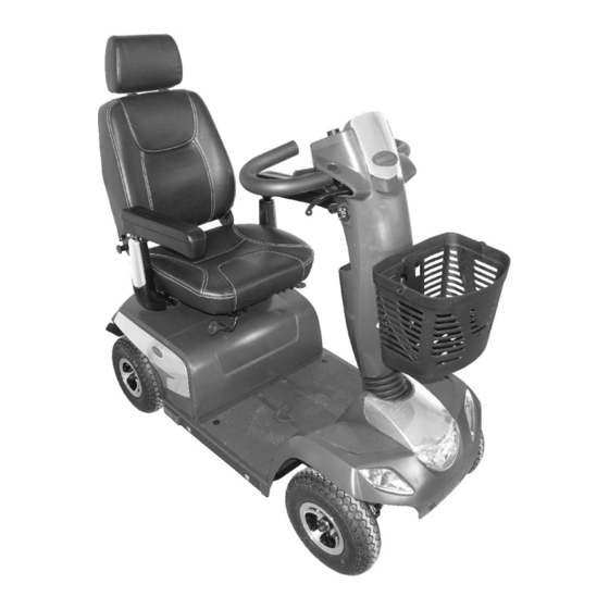
Page 20: Components
Invacare® Orion Series 3.2 Operating console (LED version) 3 Components Arrangement 3.1 Main parts of the scooter Fig. 3-1 A Disengaging lever A Status display B Unlocking lever for sliding seat rails (front right below seat) B Switching on/off curve control (reduction of speed... - Page 21 Components I Low speed mode Overdischarge protection: after a certain drive time on reserve battery power the electronic system J Drive lever switches the drive off automatically and brings the scooter to a standstill. If you do not drive your Status Display scooter for a while the batteries will "recuperate"...
-
Page 22: Operating Console (Lcd Version)
Invacare® Orion Series Battery capacity D Horn <65 % E Left-hand direction indicator (switches itself off automatically after 30 seconds) <50 % F Speed control dial <35 % G Right-hand direction indicator (switches itself off automatically after 30 seconds) <25 % H Lighting <20 %... - Page 23 Components F Left turn indication Reduced driving range. Battery capacity: Recharge the batteries at the end <25% G Settings shown: ODO, TRIP, TEMP, TIME of your journey. H Right turn indication Battery reserve = severely Battery capacity: restricted driving range. I Battery status <20% Recharge batteries immediately!
-
Page 24: Setup
Off and re-enter set-up specifications. – The mobility device is fitted with an individual, Contact Invacare, if mobility device still does multiply adjustable seating system including not perform to correct specifications. adjustable legrests, armrests, a headrest or other options. -
Page 25: Moving The Seat Position Forwards Or Backwards
Setup 1. Pull the lever A to disengage the seat. Initial setup should always be done by a healthcare 2. Slide the seat forwards or backwards into the required professional. Adjustment by the user is only position. recommended after they have been given 3. -
Page 26: Adjusting The Armrest Height
Invacare® Orion Series 1. Loosen and remove the armrest fixing screw A. 1. Turn the knobs A to loosen the fixing for the armrest. 2. Adjust the armrest to the required height. 2. Adjust the armrests to the required width. -
Page 27: Adjusting Backrest Angle
Setup 3. Adjust the screw B until the desired setting angle of the armrest has been achieved. 4. Re-tighten the counternut. 4.6 Adjusting Backrest Angle Standard Seat • 5 mm Allen key • 10 mm wrench 1. Pull lever and adjust backrest to desired angle by leaning forwards or backwards. -
Page 28: Disengaging The Seat To Rotate Or Remove It
Invacare® Orion Series 1. To raise headrest, push the release button A and lift Removing the seat headrest up to desired position. 1. Pull the lever A to disengage the seat. 2. To lower headrest, push the release button and lower 2. - Page 29 Setup 1. Push the lever A downwards to adjust the steering column. 2. Hold the lever and move the steering column forwards or backwards until it fits to your requirements. 3. Release the lever. The lever automatically switches back to its position.
-
Page 30: Accessories
Invacare® Orion Series The belt can only be adjusted on one side, which can result 5 Accessories in the buckle not being in the middle of the waist (across pelvic area) after adjustment has taken place. 5.1 Posture belts 5.1.2 Adjusting the posture belt correctly... -
Page 31: Installing The Posture Belt
Accessories 5.1.3 Installing the posture belt 1. Take hold of the belt mounting and hold it in front of the hole in the mounting bracket. • 12 mm wrench • 13 mm wrench The mounting brackets (1) for attaching the belt, are located Position the bolt (1), screw the nut on from the other under the seat (the figure shows only the left hand side). -
Page 32: Attaching The Rollator
Invacare® Orion Series Only the following rollators have been approved by Invacare 5.2.1 Attaching the rollator to be transported using this rollator bracket: Dolomite Jazz 600 • Dolomite Jazz 600 • Dolomite Legacy 600 • Invacare Banjo P452E/3 CAUTION! Risk of tipping as a result of altered center of... -
Page 33: Removing The Rollator Bracket
Accessories 5.2.3 Positioning the rear reflector Invacare Banjo P452E/3 CAUTION! Risk of accident due to poor visibility If you wish to use your mobility device on public roads and a rear reflector is required by national legislation, then the rollator bracket may not cover the rear reflector. - Page 34 Invacare® Orion Series Change the armrest shroud Change the rear side shroud Change the head shroud Change the front side shroud 1603456-D...
-
Page 35: Usage
Usage 6 Usage 6.1 Getting in and out Pull the detent lever A. The armrest can be swivelled upwards to assist getting in and out. The seat can also be rotated to assist getting in and out. Turn the seat to the side. 1603456-D... -
Page 36: Before Driving For The First Time
Invacare® Orion Series 6.3.2 Safety information when ascending obstacles Information on turning the seat The detent automatically engages again in WARNING! eight-turns. Risk of tipping over – Never approach obstacles at an angle but at 90 degrees as shown below. -
Page 37: Parking And Stationary
Usage 6.5 Parking and stationary WARNING! Risk of tipping over If you park your vehicle, or leave it idle or unattended for – Only ever drive downhill at a maximum of 2/3 a longer period: of the top speed. – If your scooter is fitted with an adjustable 1. -
Page 38: Driving The Scooter
4. Pull the left-hand drive lever carefully to travel in reverse. 1. Pull lever to rear. The drive is engaged. The control system is programmed with standard values in the works. Your Invacare provider can carry out programming tailored to fit your requirements. 1603456-D... -
Page 39: Switching The Lights On And Off
– Changes to the drive program may only be carried out by trained Invacare providers. – Invacare supplies all mobility products with a standard drive program ex-works. Invacare can Press the Direction indicator key for left or right. -
Page 40: Switching The Low Speed Mode On And Off
Invacare® Orion Series An acoustic signal sounds. Deactivating curve control 6.13 Switching the low speed mode on and off Your scooter is fitted with a low speed mode. This function lowers the scooter’s speed. Press the setting key for five seconds. The LED beside the key and the symbol for curve control in the LCD display (if fitted) illuminate. -
Page 41: Adjusting Display
Usage Switching between modes TRIP mode: Press both direction indicator keys to reset last trip. 1. Press the setting key to switch between the modes, shown in the display. Adjusting modes You can adjust the modes to your requirements. TEMP mode: Press left indicator key to select °C or °F. Press the setting key to choose the mode you want to TIME mode: Press right indicator key to select hour adjust. - Page 42 Invacare® Orion Series LED Display Function Volume Setup Volume Indication The volume of acoustic signals for turning, low battery, reversing and turned-on hazard lights can be adjusted. Reverse Low Battery The volume setup keys and volume indications for various Turn Indicator...
- Page 43 Usage 1. Turn off controls. 1. Turn off controls. Press and hold both direction indicator keys. Press and hold both direction indicator keys A and B. 3. Turn on controls. 3. Turn on controls. 4. After two seconds LED 8 flashes. Release both keys 4.
- Page 44 Invacare® Orion Series Adjusting Backlight (only LCD Display) Adjusting Time Setup (only LCD Display) Press indicator keys A or B to adjust backlight intensity. Press indicator keys A or B to adjust time setup. 2. Press Setting mode key E for saving and enter next 2.
-
Page 45: Controls System
7 Controls system A defective main fuse may be replaced only after checking the entire electrical system. A specialized Invacare provider must perform the replacement. 7.1 Electronics Protection System You can find information on the fuse type in 12 Technical Data, page 61. -
Page 46: How To Charge The Batteries
Use only charging devices in Class 2. This class of – Do not use the battery charger if it has been chargers may be left unattended during charging. All dropped or damaged. charging devices which are supplied by Invacare comply with these requirements. WARNING! •... -
Page 47: How To Disconnect The Batteries After Charging
Controls system • Do not leave the batteries in a low state of charge WARNING! for an extended length of time. Charge a discharged Risk of fire and electric shock if a damaged battery as soon as possible. extension cable is used •... -
Page 48: Transporting Batteries
Invacare® Orion Series • Driving with blinking red LED means an extreme stress 7.2.7 Transporting batteries for the battery and should be avoided under normal The batteries supplied with your mobility device are circumstances. not hazardous goods. This classification is based on the •... -
Page 49: How To Handle Damaged Batteries Correctly
Disposing of dead or damaged batteries correctly Open the battery retaining strap A. Dead or damaged batteries can be given back to your provider or directly to Invacare. 4. Unplug battery connecting plug B. 5. Remove battery. 6. Repeat procedure for other battery. -
Page 50: Transport
– If you are unsure how much your mobility device weighs, then you must have it weighed CAUTION! using calibrated scales. Risk of injury – If you are unable to fasten your mobility device securely in a transport vehicle, Invacare recommends that you do not transport it. 1603456-D... - Page 51 • Before transporting your mobility device, make sure the motors are engaged and that the remote is switched off. Invacare strongly recommends that you additionally disconnect or remove the batteries. Refer to Removing the batteries. •...
-
Page 52: Maintenance
The following tables list inspection checks that should be performed by the user within the indicated intervals. If the mobility device fails to pass one of the inspection checks, refer to the chapter indicated or contact your authorized Invacare provider. A more comprehensive list of inspection checks and instructions for maintenance work can be found in the service manual for this device, which can be obtained from Invacare. -
Page 53: Wheels And Tyres
Maintenance Weekly Item Inspection check If inspection is not passed Armrests / side parts Check that armrests are firmly attached Tighten the screw or clamping lever that holds the in their holders and do not wobble. armrest (refer to 4.3 Adjusting the armrest width, page 25). -
Page 54: Long-Term Storage
For recommended tyre pressure see inscription on tyre/rim or contact Invacare. Compare table below for conversion. Storing Mobility Device and Batteries •... - Page 55 Preparing Mobility Device for Use • Re-connect the battery supply to the power module. • The batteries must be charged before use. • Have the mobility device checked by an authorised Invacare provider. 1603456-D...
-
Page 56: After Use
Electric components and printed circuit boards are disposed of as electronic scrap. • Exhausted or damaged batteries can be returned to your medical equipment supplier or Invacare. • Disposal must be carried out in accordance with the respective national legal provisions. -
Page 57: Troubleshooting
Troubleshooting LED Console 11 Troubleshooting 11.1 Diagnosis and Fault Repair The electronic system offers diagnostic information to support the technician during the recognition and rectification of faults on the scooter. Fig. 11-1 The electronic system reacts differently depending on the If there is a fault, the status display (1) flashes several times, seriousness of the fault and its effect on user safety. -
Page 58: Error Codes And Diagnostic Codes
Invacare® Orion Series 11.1.2 Error Codes And Diagnostic Codes Consequence for the Flash code Fault scooter Comments Batteries must be Continues to drive • The batteries are discharged. Charge the batteries as charged soon as possible. Battery voltage too low Stops driving •... - Page 59 Ensure that the disengaging lever is in the engaged position. • There is a defect in the braking coil or in the cabling. Check the magnetic brake and cabling for open or short-circuited circuitry. Contact your Invacare provider. No neutral position when Stops driving •...
- Page 60 Invacare® Orion Series Consequence for the Flash code Fault scooter Comments Miscellaneous internal Stops driving • Contact your Invacare provider. fault Stops moving • The scooter has exceeded the permissible maximum Push/freewheel mode speed during pushing or freewheeling. Switch the error electronics system off and on again.
-
Page 61: Technical Data
Technical Data 12 Technical Data 12.1 Technical Specifications The technical information provided hereafter applies to a standard configuration or represents maximum achievable values. These can change if accessories are added. The precise changes to these values are detailed in the sections for the respective accessories. - Page 62 Invacare® Orion Series Electrical System Orion METRO Orion Motor • 6 km/h: S1: 240 W, Maxpeak 500 W • 6 km/h: S1 240 W, Maxpeak 500 W (only • 10 km/h: S1: 240 W, Maxpeak 600 W 4–wheel) • 12 km/h: S1: 550 W, Maxpeak 1500 W •...
- Page 63 Technical Data Driving Characteristics Orion METRO Orion Speed • 6 km/h • 6 km/h (only 4–wheel) • 10 km/h • 10 km/h • 12 km/h • 12 km/h • 12.8 km/h • 15 km/h Min. braking distance • 1000 mm (6 km/h) •...
- Page 64 Invacare® Orion Series Dimensions According to ISO 7176–15 Orion METRO Orion Total length • 3-wheel: 1240 mm • 3–wheel: 1300 mm • 4-wheel: 1270 mm • 4–wheel: 1320 mm • 660 mm Drive unit width • 3–wheel: 690 mm •...
- Page 65 Technical Data Dimensions According to ISO 7176–15 Orion METRO Orion Seat height (seatbase to Standard, Comfort and Premium seat: Standard, Comfort and Premium seat: floor pan distance) • 440/465/490/515 mm • 3–wheel: 440/465 mm • 4–wheel: 440/465/490/515 mm • 550 mm ... 625 mm Seat surface height at front edge Seat angle...
- Page 66 Invacare® Orion Series Component Weights Orion METRO Orion Chassis • 3-wheel: approx. 52 kg • 4–wheel: approx. 62 kg • 4-wheel: approx. 57 kg Seat unit • approx. 21 kg • 3–wheel: 26 kg • 4–wheel: 21 kg Batteries •...
- Page 67 Technical Data Note: The drive range of a mobility device is strongly influenced by external factors, such as the speed setting of the wheelchair, the charging state of the batteries, surrounding temperature, local topography, road surface characteristics, tyre pressure, weight of user, drive style and use of batteries for lighting, servos etc. The specified values are theoretical maximum achievable values measured according to ISO 7176-4.
-
Page 68: Service
Invacare® Orion Series 13 Service 13.1 Inspections performed It is confirmed by stamp and signature that all jobs listed in the inspection schedule of the service and repair instructions have been properly performed. The list of the inspection jobs to be performed can be found in the service manual which is available through Invacare. - Page 69 Service Stamp of authorized provider / Date / Signature Stamp of authorized provider / Date / Signature 4th Annual Inspection 5th Annual Inspection Stamp of authorized provider / Date / Signature Stamp of authorized provider / Date / Signature 1603456-D...
- Page 70 Notes...
- Page 71 Notes...
- Page 72 Invacare representatives/distributors Australia: Canada: Ireland: New Zealand: Invacare Australia Pty. Ltd. Invacare Canada L.P. Invacare Ireland Ltd, Invacare New Zealand Ltd 1 Lenton Place, North Rocks NSW 570 Matheson Blvd East, Unit 8 Unit 5 Seatown Business Campus 4 Westfield Place, Mt Wellington 1060 2151 CDN Mississauga, On.
Need help?
Do you have a question about the Orion Series and is the answer not in the manual?
Questions and answers