Advertisement
Quick Links
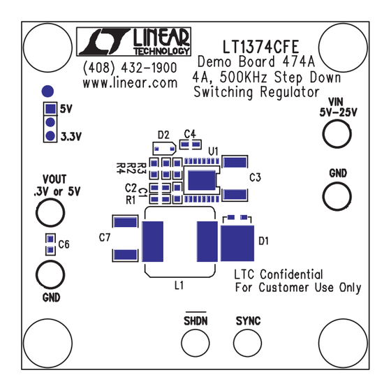
QUICK START GUIDE FOR DEMONSTRATION CIRCUIT 474
DESCRIPTION
Demonstration circuit 474 is a step-
down
buck
regulator
LT1374CFE 500kHz-switching regulator.
The high switching frequency allows
the use of small inductors and filter
components, making this circuit ideal
for space conscious systems.
0. 95
0. 9
0. 85
0. 8
0
1
Figure 1.
Efficiency, 10V V
Figure 1 shows efficiency versus load
for a typical application. The best
efficiency is realized with a load
QUICK START PROCEDURE
Refer to Figure 3 for proper measure-
ment equipment setup and follow the
procedure below:
Connect input power to the Vin and
1.
GND terminals. V
tween 5V and 25V. The power source
should
be
capable
25W.
5V output operation requires
NOTE:
a minimum V
of 6V
IN
Connect the output load to the Vout
2.
and GND terminals.
4A, 500KHZ STEP DOWN SWITCHING REGULATOR
using
2
3
4
5
Loa d Cur r e nt
, 5V V
IN
should be be-
IN
of
delivering
current
between
the
Full
load
maximum allowed die temperature is
125°C. Figure 2 shows die temperature
vs. output load current with V
12V. At full load the die temperature
rise is 70°C indicating that the demo
is suitable for ambient temperatures
of up to 125°C – 70°C = 55°C.
80
60
40
20
0
0
Figure 2.
OUT
Select desired output voltage using
3.
the voltage selecting jumper
Choose 3.3V operation by mov-
NOTE:
ing the voltage selection jumper to
the
3.3V
circuit 474 is optimized for 5V op-
eration, and when operating at 3.3V
out, high V
instability may arise. Increasing
the output capacitance removes this
instability. Use a 330µF, 4V, low
ESR cap such as the "Poscap" or
"Oscon".
LT1374CFE
700mA
and
efficiency
is
1
2
3
Loa d ( Amps )
Die Temperature vs Output
Current, V
= 12V
IN
position.
Demonstration
and light load some
IN
2
amps.
87%.
The
of
IN
4
1
Advertisement

Related Manuals for Linear Technology LT1374CFE


Summary of Contents for Linear Technology LT1374CFE
- Page 1 Full load efficiency 87%. LT1374CFE 500kHz-switching regulator. maximum allowed die temperature is The high switching frequency allows 125°C. Figure 2 shows die temperature the use of small inductors and filter vs. output load current with V components, making this circuit ideal 12V.
- Page 2 QUICK START GUIDE FOR DEMONSTRATION CIRCUIT 474 4A, 500KHZ STEP DOWN SWITCHING REGULATOR To turn the circuit off, ground the This is especially true at high cur- terminal labeled SHDN rent. Needless to say any efficiency calculation should be made using demo To test the synchronization feature circuit terminal voltages as opposed of the demo board apply a sync sig-...
- Page 3 QUICK START GUIDE FOR DEMONSTRATION CIRCUIT 474 4A, 500KHZ STEP DOWN SWITCHING REGULATOR Figure 4. Scope Probe Placement for Measuring Output Ripple...
Need help?
Do you have a question about the LT1374CFE and is the answer not in the manual?
Questions and answers