Advertisement
Description
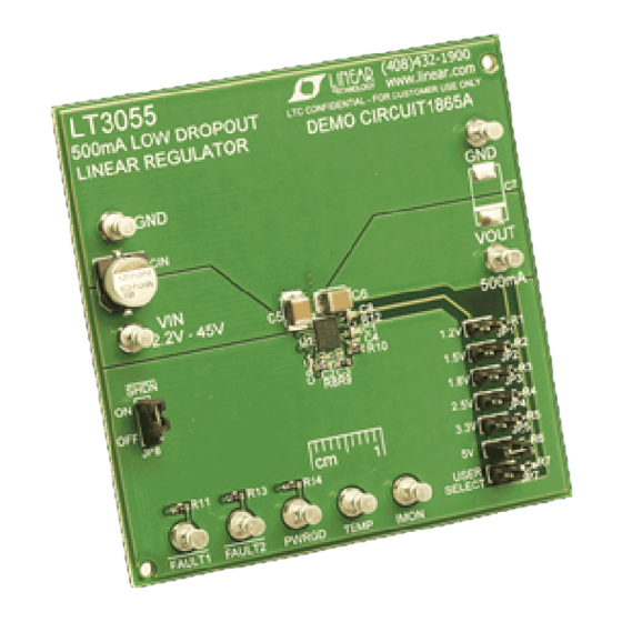
Demonstration circuit 1865A is an adjustable 500mA linear
regulator featuring
noise and low dropout voltage linear regulator. The device
supplies 500mA of output current with a dropout voltage
of 350mV. A 10nF bypass capacitor reduces output noise
to 25µV
in a 10Hz to 100kHz bandwidth and soft-starts
RMS
the reference. The LT3055's ±45V input voltage rating
combined with its precision current limit and diagnostic
functions make the IC an ideal choice for robust, high
reliability applications.
LT3055 current limit can be programmed by a single
resistor, accurate to ±10% over a wide input voltage
and temperature range. Another resistor programs the
LT3055's minimum output current monitor, useful for
detecting open-circuit conditions. The internal current limit
should be considered when the input-to-output differential
is high. The current monitor function sources a current
equal to 1/500th of output current. See the Operation sec-
performance summary
PARAMETER
Minimum Input Voltage (Max)
Maximum Input Voltage
Output Voltage V
OUT
Maximum Output Current (Typ)
Minimum Output Current (Typ)
I
Voltage (to µP ADC) (Typ)
MON
Temp voltage (Typ)
Arrow.com.
Downloaded from
Precision Current Limit and Diagnostics
LT
3055. LT3055 is a micropower, low
®
CONDITIONS
V
= 5V, I
OUT
V
= 5V
OUT
Header in JP1
Header in JP2
Header in JP3
Header in JP4
Header in JP5
Header in JP6
V
= 12V, V
IN
V
= 12V, V
IN
V
= 12V, V
IN
V
= 12V, V
IN
DEMO MANUAL DC1865A
500mA, Linear Regulator with
tion in the data sheet for a detailed calculation. Logic fault
pins assert low if the LT3055 is in current limit (FAULT2),
operating below its minimum output current (FAULT1)
or is in thermal limit (both FAULT1 and FAULT2). The die
temperature is indicated by the TEMP pin.
LT3055 optimizes stability and transient response with a
low ESR ceramic capacitor, requiring a minimum of 3.3µF.
The LT3055 is available in the thermally-enhanced 16-lead
4mm × 3mm DFN and MSOP packages.
The LT3055 data sheet gives a complete description of
the device, operation and application information. The
data sheet must be read in conjunction with this quick
start guide for DC1865.
Design files for this circuit board are available at
http://www.linear.com/demo/DC1865A
L, LT, LTC, LTM, Linear Technology and the Linear logo are registered trademarks of Linear
Technology Corporation. All other trademarks are the property of their respective owners.
Specifications are at T
= 25°C
A
= 500mA
OUT
= 5V, R10 = 604Ω
OUT
= 5V, R9 = 121kΩ
OUT
= 5V, R8 = 1k, I
= 500mA
OUT
OUT
= 5V
OUT
LT3055
VALUE
5.6V
45V
1.20V ±3%
1.50V ±3%
1.80V ±3%
2.50V ±3%
3.32V ±3%
4.99V ±3%
500mA
10mA
1V
0.25V
dc1865af
1
Advertisement
Table of Contents

Subscribe to Our Youtube Channel
Related Manuals for Linear Technology DC1865A


Summary of Contents for Linear Technology DC1865A
- Page 1 The current monitor function sources a current L, LT, LTC, LTM, Linear Technology and the Linear logo are registered trademarks of Linear equal to 1/500th of output current. See the Operation sec- Technology Corporation. All other trademarks are the property of their respective owners.
- Page 2 DEMO MANUAL DC1865A Quick start proceDure DC1865A is easy to set up to evaluate the performance 1. After all connections are made, turn on input power and of the LT3055. Refer to Figure 1 for proper measurement verify that the output voltage according to the output equipment setup and follow the procedure below: voltage selection jumper (JP1-JP7).
- Page 3 DEMO MANUAL DC1865A Quick start proceDure Figure 1. Proper Measurement Equipment Setup Figure 2. Measuring Input or Output Ripple dc1865af Arrow.com. Arrow.com. Arrow.com. Downloaded from Downloaded from Downloaded from...
- Page 4 DEMO MANUAL DC1865A parts List ITEM REFERENCE PART DESCRIPTION MANUFACTURER/PART NUMBER Required Circuit Components C1, C8 Cap., X7R, 0.01µF, 16V, 10% 0603 AVX, 0603YC103KAT2A C2, C3 Cap., X5R, 0.1µF, 16V, 20% 0402 AVX, 0402YD104MAT2A Cap., X7R, 22nF, 16V, 10% 0402...
- Page 5 Information furnished by Linear Technology Corporation is believed to be accurate and reliable. However, no responsibility is assumed for its use. Linear Technology Corporation makes no representa- tion that the interconnection of its circuits as described herein will not infringe on existing patent rights.
- Page 6 Linear Technology Corporation (LTC) provides the enclosed product(s) under the following AS IS conditions: This demonstration board (DEMO BOARD) kit being sold or provided by Linear Technology is intended for use for ENGINEERING DEVELOPMENT OR EVALUATION PURPOSES ONLY and is not provided by LTC for commercial use. As such, the DEMO BOARD herein may not be complete in terms of required design-, marketing-, and/or manufacturing-related protective considerations, including but not limited to product safety measures typically found in finished commercial goods.
Need help?
Do you have a question about the DC1865A and is the answer not in the manual?
Questions and answers