
Subscribe to Our Youtube Channel
Related Manuals for Deep Sea Electronics Plc DSE8810


Summary of Contents for Deep Sea Electronics Plc DSE8810
- Page 1 DEEP SEA ELECTRONICS PLC DSE8810 Colour Autostart Load Share Controller Operator Manual Document Number 057-163 Author: Anthony Manton DSE8800 Operator Manual ISSUE 1...
- Page 2 The DSE logo is a UK registered trademarks of Deep Sea Electronics PLC. Any reference to trademarked product names used within this publication is owned by their respective companies. Deep Sea Electronics Plc reserves the right to change the contents of this document without prior notice. Amendments List...
-
Page 3: Table Of Contents
DSE8800 Operator Manual TABLE OF CONTENTS Section Page BIBLIOGRAPHY ....................7 INSTALLATION INSTRUCTIONS .................. 7 TRAINING GUIDES ......................7 MANUALS ........................8 THIRD PARTY DOCUMENTS ..................8 INTRODUCTION ....................9 SPECIFICATIONS ..................10 PART NUMBERING ......................10 3.1.1 SHORT NAMES .....................10 TERMINAL SPECIFICATION ..................11 POWER SUPPLY REQUIREMENTS ................11 3.3.1... - Page 4 RS485 CONNECTOR .....................48 4.1.10 RS232 CONNECTOR .....................48 TYPICAL WIRING DIAGRAMS ..................49 4.2.1 DSE8810 3 PHASE, 4 WIRE WITH RESTRICTED EARTH FAULT PROTECTION 50 ALTERNATIVE TOPOLOGIES ..................51 4.3.1 3 PHASE 4 WIRE WITH UNRESTRICTED EARTH FAULT MEASURING....51 EARTH SYSTEMS ......................52 4.4.1 NEGATIVE EARTH....................52...
- Page 5 DSE8800 Operator Manual CONTROL PUSH-BUTTONS ..................70 ALTERNATIVE CONFIGURATIONS ................71 DUMMY LOAD / LOAD SHEDDING CONTROL ............72 STOP MODE .........................73 6.5.1 ECU OVERRIDE.....................73 AUTOMATIC MODE......................74 6.6.1 WAITING IN AUTO MODE ..................74 6.6.2 STARTING SEQUENCE ..................74 6.6.3 ENGINE RUNNING ....................75 6.6.4 STOPPING SEQUENCE ..................75 MANUAL MODE ......................76 6.7.1 WAITING IN MANUAL MODE ................76...
- Page 6 DSE8800 Operator Manual 12.2 METERING ......................105 12.3 COMMUNICATIONS ....................105 12.4 SYNC CHECKS ....................... 105 MAINTENANCE, SPARES, REPAIR AND SERVICING......106 13.1 PURCHASING ADDITIONAL CONNECTOR PLUGS FROM DSE ......106 13.1.1 PACK OF PLUGS ....................106 13.1.2 INDIVIDUAL PLUGS ..................... 106 13.2 PURCHASING ADDITIONAL FIXING CLIPS FROM DSE ........
-
Page 7: Bibliography
1.1 INSTALLATION INSTRUCTIONS Installation instructions are supplied with the product in the box and are intended as a ‘quick start’ guide only. DSE PART DESCRIPTION 053-137 DSE8810 Installation Instructions 053-138 DSE8820 Installation Instructions 053-139 DSE8860 Installation Instructions 053-032 DSE2548 LED Expansion Annunciator Installation Instructions... -
Page 8: Manuals
Bibliography 1.3 MANUALS Product manuals are can be downloaded from the DSE website: www.deepseaplc.com DSE PART DESCRIPTION 057-004 Electronic Engines and DSE Wiring 057-045 Guide to Synchronising and Load Sharing Part 1 057-046 Guide to Synchronising and Load Sharing Part 2 057-047 Load Share Design and Commissioning 057-164... -
Page 9: Introduction
This allows the generator OEM greater flexibility in the choice of controller to use for a specific application. The DSE8810 controller has been designed to allow the operator to start and stop the generator, and if required, transfer the load to the generator either manually (via fascia mounted push-buttons) or automatically. -
Page 10: Specifications
Specification 3 SPECIFICATIONS 3.1 PART NUMBERING 8810 Variant Product type Standard version DSE8810 8810 Autostart Module UL approved version Hardware revision Initial Release At the time of this document production, there have been no revisions to the module hardware. 3.1.1 SHORT NAMES... -
Page 11: Terminal Specification
Specification 3.2 TERMINAL SPECIFICATION Connection type Two part connector. • Male part fitted to module • Female part supplied in module packing case - Screw terminal, rising Example showing cable entry and screw clamp, no internal terminals of a 10 way connector spring. -
Page 12: Generator Voltage / Frequency Sensing
Specification 3.4 GENERATOR VOLTAGE / FREQUENCY SENSING Measurement type True RMS conversion Sample Rate 5 KHz or better Harmonics Up to 10 or better 300 K Ω ph-N Input Impedance Phase to Neutral 15 V to 333 V AC (absolute (minimum required for sensing frequency maximum) Suitable for 110 V to 277 V nominal... -
Page 13: Generator Current Sensing
Specification 3.5 GENERATOR CURRENT SENSING Measurement type True RMS conversion Sample Rate 5 kHz or better Harmonics Up to 10 or better Nominal CT secondary rating 1 A or 5 A (5 A recommended) Maximum continuous current Overload Measurement 3 x Nominal Range setting Absolute maximum overload 50 A for 1 second 0.5 VA (0.02 Ω... -
Page 14: Ct Polarity
Specification 3.5.2 CT POLARITY Take care to ensure the correct polarity of the CTs. Incorrect CT orientation will lead to negative kW readings when the set is supplying power. Take note that paper stick-on labels on CTs that show the orientation are often incorrectly placed on the CT (!). -
Page 15: Inputs
Specification 3.6 INPUTS 3.6.1 DIGITAL INPUTS 11 configurable inputs. A future firmware update to the controller Number will enable an additional input. Check with DSE Technical Support for further details. Arrangement Contact between terminal and ground Low level threshold 2.1 V minimum High level threshold 6.6 V maximum Maximum input voltage... -
Page 16: Fuel Level (Flexible) Inputs
Specification 3.6.3 FUEL LEVEL (FLEXIBLE) INPUTS The Fuel level input is also configurable as a ‘Ratiometric’ analogue inputs are provided. This is able to be configured as Digital, Resistive, 0-10 V or 4-20 mA. 3.6.3.1 FUEL LEVEL INPUT AS DIGITAL Arrangement Contact between input terminal and battery negative Low level threshold... -
Page 17: Analogue Flexible Input
Specification 3.6.4 ANALOGUE FLEXIBLE INPUT An additional flexible analogue input is provided and can be configured as Digital or Resistive. 3.6.4.1 FLEXIBLE SENSOR AS DIGITAL Arrangement Contact between input terminal and battery negative Low level threshold 2.1 V minimum High level threshold 6.6 V maximum Max input voltage +60 V DC with respect to battery negative... -
Page 18: Charge Fail Input
Specification 3.6.5 CHARGE FAIL INPUT Minimum voltage Maximum voltage 35V (plant supply) Resolution 0.2V Accuracy ± 1% of max measured voltage Excitation Active circuit constant power output Output Power 2.5W Nominal @12V and 24V Current at 12V 210mA Current at 24V 105mA The charge fail input is actually a combined input and output. -
Page 19: Outputs
Specification 3.7 OUTPUTS Ten (10) outputs are fitted to the controller. 3.7.1 OUTPUTS A & B Type Normally used for Fuel / Start outputs. Fully configurable for other purposes if the module is configured to control an electronic engine. Supplied from Emergency Stop terminal 3. -
Page 20: Communication Ports
Specification 3.8 COMMUNICATION PORTS USB Port USB2.0 Device for connection to PC running DSE configuration suite only Max distance 6m (yards) Serial Communication A single RS232 and two RS485 ports are both fitted and provide independent operation RS232 Serial port Non –... -
Page 21: Usb Connection
Specification 3.9.2 USB CONNECTION The USB port is provided to give a simple means of connection between a PC and the controller. Using the DSE Configuration Suite Software, the operator is then able to control the module, starting or stopping the generator, selecting operating modes, etc. Additionally, the various operating parameters (such as output volts, oil pressure, etc.) of the remote generator are available to be viewed or changed. -
Page 22: Rs232
Specification 3.9.4 RS232 The RS232 port on the controller supports the Modbus RTU protocol. The Gencomm register table for the controller is available upon request from the DSE Technical Support Department. RS232 is for short distance communication (max 15m) and is typically used to connect the controller to a telephone or GSM modem for more remote communications. -
Page 23: Recommended External Modems
Specification 3.9.4.2 RECOMMENDED EXTERNAL MODEMS: • Multitech Global Modem – MultiModem ZBA (PSTN) DSE Part Number 020-252 (Contact DSE Sales for details of localisation kits for these modems) • Sierra Fastrak Xtend GSM modem kit (PSU, Antenna and modem)* DSE Part number 0830-001-01 NOTE: *For GSM modems a SIM card is required, supplied by your GSM network provider: •... -
Page 24: Rs485
Specification 3.9.5 RS485 The RS485 ports on the controller support the Modbus RTU protocol. The DSE Gencomm register table for the controller is available upon request from the DSE Technical Support Department. RS485 is used for point-to-point cable connection of more than one device (maximum 32 devices) and allows for connection to PCs, PLCs and Building Management Systems (to name just a few devices). -
Page 25: Ethernet
Specification 3.9.6 ETHERNET The module is fitted with ETHERNET socket for connection to LAN (local area networks) Description Do not connect Do not connect Do not connect Do not connect 3.9.6.1 DIRECT PC CONNECTION Requirements • DSE8800 series module • Crossover Ethernet cable (see Below) •... -
Page 26: Connection To Basic Ethernet
Specification Crossover cable wiring detail Two pairs crossed, two pairs uncrossed 10baseT/100baseTX crossover For the advanced Engineer, a crossover cable is a CAT5 cable Connection 1 (T568A) Connection 2 (T568B) with one end terminated as T568A and the other end white/green stripe white/orange stripe terminated as T568B. -
Page 27: Connection To Company Infrastructure Ethernet
Specification Ethernet cable wiring detail 10baseT/100baseT For the advanced Connection 1 (T568A) Connection 2 (T568A) Engineer, this cable has both ends terminated as T568A white/green stripe white/green stripe (as shown below) or T568B. green solid green solid white/orange stripe white/orange stripe blue solid blue solid white/blue stripe... -
Page 28: Connection To The Internet
Specification Ethernet cable wiring detail For the advanced Engineer, this cable 10baseT/100baseT has both ends terminated as T568A (as shown below) or Connection 1 (T568A) Connection 2 (T568A) T568B. white/green stripe white/green stripe green solid green solid white/orange stripe white/orange stripe blue solid blue solid white/blue stripe... - Page 29 Specification Ethernet cable wiring detail 10baseT/100baseT For the advanced Engineer, this cable has both ends Connection 1 (T568A) Connection 2 (T568A) terminated as T568A (as shown below) or T568B. white/green stripe white/green stripe green solid green solid white/orange stripe white/orange stripe blue solid blue solid white/blue stripe...
-
Page 30: Firewall Configuration For Internet Access
Specification 3.9.6.5 FIREWALL CONFIGURATION FOR INTERNET ACCESS As modem/routers differ enormously in their configuration, it is not possible for DSE to give a complete guide to their use with the module. However it is possible to give a description of the requirements in generic terms. -
Page 31: Dsenet® For Expansion Modules
Specification 3.10 DSENET® FOR EXPANSION MODULES DSENet® is the interconnection cable between the host controller and the expansion module(s) and must not be connect to any device other than DSE equipment designed for connection to the DSENet® Cable type Two core screened twisted pair Cable characteristic 120Ω... -
Page 32: Sounder
Specification 3.11 SOUNDER The module features an internal sounder to draw attention to warning, shutdown and electrical trip alarms. Sounder level 64db @ 1m 3.11.1 ADDING AN EXTERNAL SOUNDER TO THE APPLICATION Should an external alarm or indicator be required, this can be achieved by using the DSE Configuration Suite PC software to configure an auxiliary output for “Audible Alarm”, and by configuring an auxiliary input for “Alarm Mute”... -
Page 33: Dimensions And Mounting
Specification 3.13 DIMENSIONS AND MOUNTING 3.13.1 DIMENSIONS 245 mm x 184 mm x 50 mm (9.6” x 7.2” x 2.0”) 3.13.2 PANEL CUTOUT 220mm x 160mm (8.7” x 6.3”) 3.13.3 WEIGHT 0.7kg (1.4lb) 3.13.4 FIXING CLIPS The module is held into the panel fascia using the supplied fixing clips. •... -
Page 34: Cable Tie Fixing Points
Specification 3.13.5 CABLE TIE FIXING POINTS Integral cable tie fixing points are included on the rear of the module’s case to aid wiring. This additionally provides strain relief to the cable loom by removing the weight of the loom from the screw connectors, thus reducing the chance of future connection failures. -
Page 35: Applicable Standards
Specification 3.14 APPLICABLE STANDARDS This document conforms to BS4884-1 1992 Specification for presentation BS 4884-1 of essential information. BS 4884-2 This document conforms to BS4884-2 1993 Guide to content BS 4884-3 This document conforms to BS4884-3 1993 Guide to presentation BS EN 60068-2-1 (Minimum -30°C (-22°F) - Page 36 Specification Continued overleaf.
- Page 37 Specification IEEE C37.2 Continued… (Standard Electrical Power System Device 50 – Instantaneous overcurrent relay 51 – AC time overcurrent relay Function Numbers and 52 – AC circuit breaker Contact Designations) 53 – Exciter or DC generator relay 54 – Turning gear engaging device 55 –...
-
Page 38: Enclosure Classifications
Specification 3.14.1 ENCLOSURE CLASSIFICATIONS IP CLASSIFICATIONS The modules specification under BS EN 60529 Degrees of protection provided by enclosures IP65 (Front of module when module is installed into the control panel with the optional sealing gasket). IP42 (front of module when module is installed into the control panel WITHOUT being sealed to the panel) First Digit Second Digit Protection against contact and ingress of solid objects... -
Page 39: Nema Classifications
Specification 3.14.2 NEMA CLASSIFICATIONS The modules NEMA Rating (Approximate) 12 (Front of module when module is installed into the control panel with the optional sealing gasket). 2 (front of module when module is installed into the control panel WITHOUT being sealed to the panel) NOTE: - There is no direct equivalence between IP / NEMA ratings. -
Page 40: Installation
Installation 4 INSTALLATION The module is designed to be mounted on the panel fascia. For dimension and mounting details, see the section entitled Specification, Dimension and mounting elsewhere in this document. 4.1 TERMINAL DESCRIPTION To aid user connection, icons are used on the rear of the module to help identify terminal functions. An example of this is shown below. -
Page 41: Dc Supply, Fuel And Start Outputs, Outputs E-J
Installation 4.1.1 DC SUPPLY, FUEL AND START OUTPUTS, OUTPUTS E-J DESCRIPTION CABLE NOTES SIZE DC Plant Supply Input 2.5mm² (Negative) AWG 13 (Recommended Maximum Fuse 15A anti-surge) DC Plant Supply Input 2.5 mm² Supplies the module (2A anti-surge requirement) and (Positive) AWG 13 Output relays E,F,G &... -
Page 42: Analogue Sensor
Installation 4.1.2 ANALOGUE SENSOR DESCRIPTION CABLE NOTES SIZE 0.5mm² Sensor Common Return Return feed for sensors AWG 20 0.5mm² Oil Pressure Input Connect to Oil pressure sensor AWG 20 0.5mm² Coolant Temperature Input Connect to Coolant Temperature sensor AWG 20 0.5mm²... -
Page 43: Magnetic Pickup, Can And Expansion
Installation 4.1.3 MAGNETIC PICKUP, CAN AND EXPANSION DESCRIPTION CABLE NOTES SIZE 0.5mm² Magnetic pickup Positive Connect to Magnetic Pickup device AWG 20 0.5mm² Magnetic pickup Negative Connect to Magnetic Pickup device AWG 20 Magnetic pickup screen Shield Connect to ground at one end only 0.5mm²... -
Page 44: Load Switching And V1 Generator Voltage Sensing
Installation 4.1.4 LOAD SWITCHING AND V1 GENERATOR VOLTAGE SENSING DESCRIPTION CABLE NOTES SIZE 1.0mm Normally configured to control mains contactor coil Output relay C AWG 18 (Recommend 10A fuse) 1.0mm Output relay C Normally configured to control mains contactor coil AWG 18 1.0mm Normally configured to control generator contactor coil... -
Page 45: Generator Current Transformers
Installation 4.1.6 GENERATOR CURRENT TRANSFORMERS WARNING!:- Do not disconnect this plug when the CTs are carrying current. Disconnection will open circuit the secondary of the C.T.’s and dangerous voltages may then develop. Always ensure the CTs are not carrying current and the CTs are short circuit connected before making or breaking connections to the module. - Page 46 Installation CT CONNECTIONS or K is the primary of the CT that ‘points’ towards the GENERATOR or L is the primary of the CT that ‘points’ towards the LOAD s1 is the secondary of the CT that connects to the DSE Module’s input for the CT measuring (I1,I2,I3) s2 is the secondary of the CT that should be commoned with the s2 connections of all the other CTs and connected to the CT common terminal of the module.
-
Page 47: Configurable Digital Inputs
Typically, they extend USB up to 50m (yards). The supply and support of this type of equipment is outside the scope of Deep Sea Electronics PLC. CAUTION!: Care must be taken not to overload the PCs USB system by connecting more than the recommended number of USB devices to the PC. -
Page 48: Rs485 Connector
Installation 4.1.9 RS485 CONNECTOR Two, independently configurable RS485 ports are provided. Typical examples of devices that can be connected to these ports are PCs, PLCs, HMIs, Modbus engines PIN No NOTES Port1 A (-) Two core screened twisted pair cable. Port1 120Ω... -
Page 49: Typical Wiring Diagrams
Installation 4.2 TYPICAL WIRING DIAGRAMS As every system has different requirements, these diagrams show only a TYPICAL system and do not intend to show a complete system. Genset manufacturers and panel builders may use these diagrams as a starting point; however, you are referred to the completed system diagram provided by your system manufacturer for complete wiring detail. -
Page 50: Dse8810 3 Phase, 4 Wire With Restricted Earth Fault Protection
Installation 4.2.1 DSE8810 3 PHASE, 4 WIRE WITH RESTRICTED EARTH FAULT PROTECTION NOTE:- Earthing the neutral conductor ‘before’ the neutral CT allows the module to read earth faults ‘after’ the CT only (Restricted to load / downstream of the CT) Earthing the neutral conductor ‘after’... -
Page 51: Alternative Topologies
Installation 4.3 ALTERNATIVE TOPOLOGIES The controller is factory configured to connect to a 3 phase, 4 wire Star connected alternator. This section details connections for alternative AC topologies. Ensure to configure the controller to suit the required topology. NOTE:- Refer to DSE8800 Series Configuration Suite Manual (DSE part 057-164) for further details on configuring, monitoring and control. -
Page 52: Earth Systems
Installation 4.4 EARTH SYSTEMS 4.4.1 NEGATIVE EARTH The typical wiring diagrams located within this document show connections for a negative earth system (the battery negative connects to Earth) 4.4.2 POSITIVE EARTH When using a DSE module with a Positive Earth System (the battery positive connects to Earth), the following points must be followed: •... - Page 53 Installation...
-
Page 54: Description Of Controls
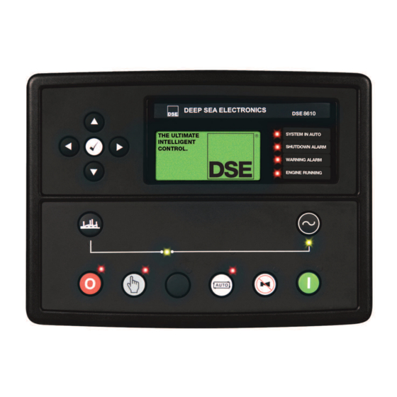
Description Of Controls 5 DESCRIPTION OF CONTROLS 5.1 DSE8810 AUTO START CONTROL MODULE Main Status and Instrumentation Display Menu Navigation Buttons Close Generator Open Generator (Manual Mode Only) (Manual Mode Only) Start Engine (When in Select Stop Manual) Mode Mute alarm /... -
Page 55: Quickstart Guide
Description Of Controls 5.2 QUICKSTART GUIDE This section provides a quick start guide to the module’s operation. 5.2.1 STARTING THE ENGINE First, Select Manual Mode… …Then Press the Start Button to Crank the Engine. NOTE:- For further details, see the section entitled ‘OPERATION’ elsewhere in this manual. 5.2.2 STOPPING THE ENGINE Select Stop/Reset Mode. -
Page 56: Viewing The Instrument
Description Of Controls 5.3 VIEWING THE INSTRUMENT PAGES 5.3.1 DISPLAY OVERVIEW Side Scroll Bar The Top Section Shows a Summary of the Status Main Instrumentation Display The Bottom Line of the Instrument Display Indicates the Currently Selected Page 5.3.2 PAGE INDICATORS Alarms Schedule Status... -
Page 57: Side Scroll Bar
Description Of Controls 5.3.3 SIDE SCROLL BAR While a page is being viewed, the scroll bar at the side of the display represents how ‘far down’ the page you are currently viewing. Pressing the scroll buttons moves up and down the currently selected page. Examples The blue section The blue section... -
Page 58: Home
Description Of Controls 5.3.5 HOME In addition to the common display area, the following instruments are displayed on the home page. Example image : • Bus Voltage (ph-N) • Bus Voltage (ph-ph) Generator • Generator Voltage (ph-N) • Generator Voltage (ph-ph) •... -
Page 59: Engine
Description Of Controls 5.3.6 ENGINE In addition to the common display area, the following instruments are displayed on the home page. Example image: • Engine Speed (RPM) • Oil Pressure • Coolant Temperature • Engine Battery Volts • Charge Alternator Volts •... -
Page 60: Generator
Description Of Controls 5.3.7 GENERATOR Contains electrical values of the generator (alternator), measured or derived from the module’s voltage and current inputs. Example image: Minimum and Maximum hold for the selected instrument. This can be reset in the “maintenance editor”. •... -
Page 61: Bus
Description Of Controls Total • Generator Load (kW, kV A, kV Ar, Power Factor) Mains Decoupling • R.O.C.O.F (Instantaneous reading and peak hold) • Vector Shift (Instantaneous reading and peak hold) 5.3.8 BUS Example image: • Bus Voltage (ph-ph) • Bus Voltage (ph-N) •... -
Page 62: Alarms
Description Of Controls 5.3.9 ALARMS • List of currently active alarms Example image: Event Log • Alarm History containing up to 250 past events logged. Where more than 250 events are logged, the last 250 are displayed. • Press Tick to enter the event log, then press scroll up/down to navigate through the past events. •... -
Page 63: Schedule
Description Of Controls 5.3.10 SCHEDULE Allows the user to view the run schedule and maintenance alarm settings. Example images:... -
Page 64: Status
Description Of Controls 5.3.11 STATUS Allows the user to view status information about the controller. Depending upon configuration of the controller, the information displayed will change. Information Model 8810 USB ID 0x0000BC12563 Control V1.00.02 Graphics V1.00.03 Analogue V3.00.02 Engine V1.18 Bootloader Control V1.00 Bootloader Graphics... - Page 65 Description Of Controls Many GSM modems are fitted with a status LED to show operator cell status and ringing indicator. These can be a useful troubleshooting tool. In the case of GSM connection problems, try calling the DATA number of the SIMCARD with an ordinary telephone.
- Page 66 Description Of Controls RS485 Port 1 / Port 2 Slave ID Baud Rate 115200 Tx Packets 1562 Rx Packets 1562 Exception Packets This section is included to give information about the currently selected serial port and external modem (if connected). The items displayed on this page will change depending upon configuration of the module.
- Page 67 Description Of Controls Ethernet Port Up DHCP enable Disabled Host Name IP address 192.168.10.23 Modbus Port Number Subnet Mask 255.255.255.0 Gateway IP 0.0.0.0 DNS IP 0.0.0.0 MAC Address 008080EF1F2F3 Ethernet Traffic DHCP enable Disabled Tx Packets 1562 Rx Packets 1562 Exception Packets USB Traffic Tx Packets...
- Page 68 Description Of Controls Identity Site Identity Deep Sea Electronics Genset Identity Generator #5 Load State Generator Open Protections Protections Enabled SPI Status AC Packets Rx 11363 Engine Packets Rx 11363 NV Packets Rx 11363 SMS Packets Rx Reconnect Attempts...
-
Page 69: Operation
Operation 6 OPERATION 6.1 CONTROL Control of the module is via push buttons mounted on the front of the module with STOP/RESET, MANUAL, TEST, AUTO, ALARM MUTE and START functions. For normal operation, these are the only controls which need to be operated. -
Page 70: Control Push-Buttons
Operation 6.2 CONTROL PUSH-BUTTONS Stop / Reset This button places the module into its Stop/Reset mode. This will clear any alarm conditions for which the triggering criteria have been removed. If the engine is running and the module is in Stop mode, the module will automatically instruct the changeover device to unload the generator (‘Close Generator’... -
Page 71: Alternative Configurations
Operation Menu navigation Used for navigating the instrumentation, event log and configuration screens. For further details, please see the more detailed description of these items elsewhere in this manual. 6.3 ALTERNATIVE CONFIGURATIONS Depending upon the configuration of your system by the generator supplier, the system may have selectable configurations (for example to select between 50Hz and 60Hz running). -
Page 72: Dummy Load / Load Shedding Control
Operation 6.4 DUMMY LOAD / LOAD SHEDDING CONTROL This feature may be enabled by the system designer to ensure the loading on the generator is kept to a nominal amount. If the load is low, ‘dummy loads’ (typically static load banks) can be introduced to ensure the engine is not too lightly loaded. -
Page 73: Stop Mode
Operation 6.5 STOP MODE STOP mode is activated by pressing the button. In STOP mode, the module will immediately remove the generator from load (if necessary) before stopping the engine if it is already running. No cooling run is provided for this operation. Where a cooling run is required, switch to MANUAL mode and open the breaker manually. -
Page 74: Automatic Mode
Operation 6.6 AUTOMATIC MODE NOTE:- If a digital input configured to panel lock is active, changing module modes will not be possible. Viewing the instruments and event logs is NOT affected by panel lock. Activate auto mode be pressing the pushbutton. -
Page 75: Engine Running
Operation 6.6.3 ENGINE RUNNING Once the engine is running, the Warm Up timer, if selected, begins, allowing the engine to stabilise before accepting the load. If the common bus is measured to be ‘dead bus’, the load breaker is closed. If the bus is measured to be ‘live bus’, synchronising takes place before the breaker is closed. -
Page 76: Manual Mode
Operation 6.7 MANUAL MODE NOTE:- If a digital input configured to panel lock is active, changing module modes will not be possible. Viewing the instruments and event logs is NOT affected by panel lock. Activate Manual mode be pressing the pushbutton. -
Page 77: Engine Running
If the bus is measured to be ‘live bus’, synchronising takes place before the breaker is closed. Once the load has been transferred to the generator, the load switch will not be automatically opened unless: • Press the Open Generator button (DSE8810 only) • Press the auto mode button to return to automatic mode. -
Page 78: Protections
Protections 7 PROTECTIONS When an alarm is present, the Audible Alarm will sound and the LCD display indicates the alarm(s) that are present : Shutdown Low Oil Pressure 1 of 1 The audible alarm can be silenced by pressing the Mute button To reset the alarm, address the cause of the alarm, then press the Stop/Reset button 7.1 PROTECTIONS DISABLED User configuration is possible to prevent Shutdown / Electrical Trip alarms from stopping the engine. -
Page 79: Indication / Warning Alarms
Protections 7.1.1 INDICATION / WARNING ALARMS Under Indication or Warning alarms: • The module operation is unaffected by the Protections Disabled feature. See sections entitled Indications and Warnings elsewhere in this document. 7.1.2 SHUTDOWN / ELECTRICAL TRIP ALARMS NOTE:- The EMERGENCY STOP input and shutdown alarm continues to operate even when Protections Disabled has been activated. -
Page 80: Can Alarms
Protections 7.1.3 CAN ALARMS NOTE:- Please refer to the engine manufacturer’s documentation for ECU CAN error message information. CAN alarms are messages sent from the CAN ECU to the DSE controller and displayed as follows in the below tables. Display Reason CAN ECU Warning The engine ECU has detected a warning alarm and has informed the... -
Page 81: Indications
Protections 7.2 INDICATIONS Indications are non-critical and often status conditions. They do not appear on the LCD of the module as a text message. However, an output or LCD indicator can be configured to draw the operator’s attention to the event. Example •... -
Page 82: Warnings
Protections 7.3 WARNINGS Warnings are non-critical alarm conditions and do not affect the operation of the generator system, they serve to draw the operators attention to an undesirable condition. By default, warning alarms are self-resetting when the fault condition is removed. However enabling ‘all warnings are latched’... -
Page 83: High Current Warning Alarm
Protections low oil pressure pre-alarm setting level after the Safety On timer has expired. Engine High The module detects that the engine coolant temperature has exceeded the high engine temperature pre-alarm setting level after the Safety On Temperature timer has expired. Engine Low Temperature The module detects that the engine coolant temperature has fallen below the high engine temperature pre-alarm setting level. -
Page 84: Shutdowns
Protections 7.5 SHUTDOWNS NOTE:- Shutdown and Electrical Trip alarms can be disabled by user configuration. See the section entitled Protections Disabled elsewhere in this document. Shutdowns are latching alarms and stop the Generator. Clear the alarm and remove the fault then press Stop/Reset to reset the module. - Page 85 Protections Display Reason The generator output frequency has risen above the preset Generator Over Frequency level The generator output frequency has fallen below the preset Generator Under Frequency level Generator Over Voltage The generator output voltage has risen above the preset level The generator output voltage has fallen below the preset level Generator Under Voltage Oil Pressure Sensor Open...
-
Page 86: Electrical Trips
Protections 7.6 ELECTRICAL TRIPS NOTE:- Shutdown and Electrical Trip alarms can be disabled by user configuration. See the section entitled Protections Disabled elsewhere in this document. Electrical trips are latching and stop the Generator but in a controlled manner. On initiation of the electrical trip condition the module will de-energise the ‘Close Generator’... -
Page 87: High Current Shutdown / Electrical Trip Alarm
Protections 7.7 HIGH CURRENT SHUTDOWN / ELECTRICAL TRIP ALARM The overcurrent alarm combines a simple warning trip level with a fully functioning IDMT curve for thermal protection. 7.7.1 IMMEDIATE WARNING If the Immediate Warning is enabled, the controller generates a warning alarm as soon as the Trip level is reached. - Page 88 Protections This allows for overload of the set to the limits of the Typical Brushless Alternator whereby 110% overload is permitted for 1 hour. If the set load reduces, the controller then follows a cooling curve. This means that a second overload condition may trip much sooner than the first as the controller knows if the windings have not cooled sufficiently.
- Page 89 Slower than Factory setting (Time Multiplier = 72 Factory setting (Time Multiplier = 36 Faster than Factory setting (Time Multiplier = 18 ‘Fastest’ trip setting (Time Multiplier = 1...
-
Page 90: Earth Fault Shutdown / Electrical Trip Alarm
Protections 7.8 EARTH FAULT SHUTDOWN / ELECTRICAL TRIP ALARM When the module is suitably connected using the ‘Earth Fault CT’. The module measures Earth Fault and can optionally be configured to generate an alarm condition (shutdown or electrical trip) when a specified level is surpassed. -
Page 91: Short Circuit Alarm
Protections 7.9 SHORT CIRCUIT ALARM If the Short Circuit alarm is enabled, the controller begins following the IDMT ‘curve’. If the Trip is surpassed for an excess amount of time the Alarm triggers (Shutdown or Electrical trip as selected in Action). -
Page 92: Maintenance Alarm
Maintenance Alarm 7.10 MAINTENANCE ALARM Depending upon module configuration one or more levels of maintenance alarm may occur based upon a configurable schedule. Example 1 Screen capture from DSE Configuration Suite Software showing the configuration of Maintenance Alarm 1 and Maintenance Alarm When activated, the maintenance alarm can be either a warning (set continues to run) or shutdown (running the set is not possible). -
Page 93: Scheduler
Front Panel Configuration 8 SCHEDULER The controller contains an inbuilt exercise run scheduler, capable of automatically starting and stopping the set. Up to 16 scheduled start/stop sequences can be configured to repeat on a 7-day or 28-day cycle. Scheduled runs may be on load or off load depending upon module configuration. Example Screen capture from DSE Configuration Suite Software showing the configuration... -
Page 94: Front Panel Configuration
Front Panel Configuration 9 FRONT PANEL CONFIGURATION This configuration mode allows the operator limited customising of the way the module operates. Use the module’s navigation buttons to traverse the menu and make value changes to the parameters: Increase Value / Next Item Next Page Previous Page Decrease Value / Next item... -
Page 95: Accessing The Main Front Panel Configuration Editor
Front Panel Configuration 9.1 ACCESSING THE MAIN FRONT PANEL CONFIGURATION EDITOR • Ensure the engine is at rest and the module is in STOP mode by pressing the Stop/Reset button. • Press and hold the the Stop button and Tick button together. •... -
Page 96: Editing A Parameter
Front Panel Configuration 9.1.1 EDITING A PARAMETER • Enter the editor as described above. • Press the (up) (down) and (right) to cycle to the section you wish to view/change. • Then press (up) or (down) to cycle to the parameter within the section you have chosen. -
Page 97: Adjustable Parameters
Front Panel Configuration 9.1.2 ADJUSTABLE PARAMETERS Section Parameter Detail of Parameter Parameter Action Values Oil Pressure Low Oil Pressure Shutdown Trip 0.00 Bar Warning Trip 0.00 Bar Coolant Temperature High Coolant Alarms Pre-Alarm Trip 00 Deg C Inputs Electrical Trip 00 Deg C Shutdown Trip 00 Deg C... -
Page 98: Adjustable Parameters (Maintenance Configuration Editor)
Front Panel Configuration • Description Action Activation Press (up) or (down) buttons together. USB Stick Removal Request Press Override Starting Alarms Request • Press ,(Up) or(down) (right) to cycle to the Clear AMF Alarm Clear Parameter you wish to action. Manual Fuel Pump Inactive Min / Max Session Reset... -
Page 99: Accessing The 'Running' Configuration Editor
Front Panel Configuration 9.3 ACCESSING THE ‘RUNNING’ CONFIGURATION EDITOR • The ‘running’ or editor can be entered while the engine is running. All protections remain active if the engine is running while the running editor is entered. • Press and hold the button to enter the running editor. -
Page 100: Commissioning
Commissioning 10 COMMISSIONING 10.1 PRE-COMMISSIONING Before the system is started, it is recommended that the following checks are made:- • The unit is adequately cooled and all the wiring to the module is of a standard and rating compatible with the system. Check all mechanical parts are fitted correctly and that all electrical connections (including earths) are sound. -
Page 101: Fault Finding
Fault Finding 11 FAULT FINDING 11.1 STARTING SYMPTOM POSSIBLE REMEDY Unit is inoperative Check the battery and wiring to the unit. Check the DC supply. Check the DC fuse. Read/Write configuration does not operate Unit shuts down Check DC supply voltage is not above 35 Volts or below 9 Volts Check the operating temperature is not above 70°... -
Page 102: Alarms
Fault Finding 11.3 ALARMS SYMPTOM POSSIBLE REMEDY Unit locks out on Emergency If no Emergency Stop Switch is fitted, ensure that a DC positive Stop signal is connected to the Emergency Stop input. Check emergency stop switch is functioning correctly. Check Wiring is not open circuit. Intermittent Magnetic Pick-up Ensure that Magnetic pick-up screen only connects to earth at one sensor fault... -
Page 103: Communications
Fault Finding 11.4 COMMUNICATIONS SYMPTOM POSSIBLE REMEDY CAN DATA FAIL Indicates failure of the CAN data link to the engine ECU. Check all wiring and termination resistors (if required). Check the ECU OVERRIDE function detailed in the section entitlted OPERATION elsewhere in this manual. RS485 inoperative Check : •... -
Page 104: Instruments
Fault Finding 11.5 INSTRUMENTS SYMPTOM POSSIBLE REMEDY Inaccurate generator Check that the CT primary, CT secondary and VT ratio settings are measurements on controller correct for the application. display Check that the CTs are wired correctly with regards to the direction of current flow (p1,p2 and s1,s2) and additionally ensure that CTs are connected to the correct phase (errors will occur if CT1 is connected to phase 2). -
Page 105: Dse 4 Steps To Successful Synchronising
Commissioning and Fault Finding 12 DSE 4 STEPS TO SUCCESSFUL SYNCHRONISING Synchronising and load sharing is often considered to be a complex subject. In fact, it is very simple when broken down into smaller steps. After following the Commissioning section of this manual, the 4 Steps must be followed before any parallel operation is attempted. -
Page 106: Maintenance, Spares, Repair And Servicing
Maintenance, Spares, Repairs and Servicing 13 MAINTENANCE, SPARES, REPAIR AND SERVICING The controller is Fit and Forget. As such, there are no user serviceable parts within the controller. In the case of malfunction, you should contact your original equipment manufacturer (OEM). 13.1 PURCHASING ADDITIONAL CONNECTOR PLUGS FROM DSE If you require additional plugs from DSE, please contact our Sales department using the part numbers below. -
Page 107: Dsenet Expansion Modules
DSENet Expansion Modules 13.4 DSENET EXPANSION MODULES NOTE:- A maximum of twenty (20) expansion modules can be connected to the DSENet®. NOTE:- DSENet® utilises an RS485 connection. Using Belden 9841 (or equivalent) cable allows for the expansion cable to be extended to a maximum of 1.2km. DSE Stock and supply Belden 9841 cable. -
Page 108: Warranty
Disposal & Warranty 14 WARRANTY DSE provides limited warranty to the equipment purchaser at the point of sale. For full details of any applicable warranty, you are referred to your original equipment supplier (OEM). 15 DISPOSAL 15.1 WEEE (WASTE ELECTRICAL AND ELECTRONIC EQUIPMENT) Directive 2002/96/EC If you use electrical and electronic equipment you must store, collect, treat, recycle and dispose of WEEE separately from your other waste. - Page 110 This page is intentionally left blank.
Need help?
Do you have a question about the DSE8810 and is the answer not in the manual?
Questions and answers