Table of Contents
Advertisement
Quick Links
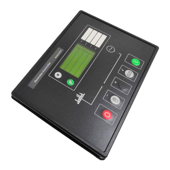
DSE Model 5210 Automatic Start Engine Management and Instrumentation System Operators Manual
Deep Sea Electronics Plc
5210 AUTOSTART MODULE
OPERATING MANUAL
Author:- Anthony Manton
Deep Sea Electronics Plc
Highfield House
Hunmanby
North Yorkshire
YO14 0PH
England
Tel: +44 (0) 1723 890099
Fax: +44 (0) 1723 893303
email: Sales@Deepseaplc.com
1
Advertisement
Table of Contents

Subscribe to Our Youtube Channel
Related Manuals for Deep Sea Electronics Plc 5210


Summary of Contents for Deep Sea Electronics Plc 5210
- Page 1 DSE Model 5210 Automatic Start Engine Management and Instrumentation System Operators Manual Deep Sea Electronics Plc 5210 AUTOSTART MODULE OPERATING MANUAL Author:- Anthony Manton Deep Sea Electronics Plc Highfield House Hunmanby North Yorkshire YO14 0PH England Tel: +44 (0) 1723 890099 Fax: +44 (0) 1723 893303 email: Sales@Deepseaplc.com...
- Page 2 DSE Model 5210 Automatic Start Engine Management and Instrumentation System Operators Manual <<< THIS PAGE INTENTIONALLY BLANK >>> 5210 OPERATING MANUAL ISSUE 2 21/05/2003 AM...
-
Page 3: Table Of Contents
DSE Model 5210 Automatic Start Engine Management and Instrumentation System Operators Manual TABLE OF CONTENTS Section Page INTRODUCTION ....................5 CLARIFICATION OF NOTATION USED WITHIN THIS PUBLICATION..5 OPERATION ....................6 AUTOMATIC MODE OF OPERATION ................6 MANUAL OPERATION ....................... 8 PROTECTIONS .................... - Page 4 DSE Model 5210 Automatic Start Engine Management and Instrumentation System Operators Manual 8.3.3 PERKINS 2800 SERIES .....................36 8.3.4 SCANIA S6........................37 8.3.5 VOLVO TAD12......................38 SPECIFICATION.....................39 COMMISSIONING ..................40 10.1.1 PRE-COMMISSIONING....................40 FAULT FINDING..................41 TYPICAL WIRING DIAGRAM..............42 FACTORY DEFAULT CONFIGURATION ...........43 ICONS AND LCD IDENTIFICATION ............46 14.1...
-
Page 5: Introduction
1 INTRODUCTION The DSE 5210 autostart module has been designed to allow the OEM to meet most of the industry’s complex specifications. It has been primarily designed to allow the user to start and stop the generator, and if required, transfer the load to the generator either manually (via external push-buttons) or automatically. -
Page 6: Operation
DSE Model 5210 Automatic Start Engine Management and Instrumentation System Operators Manual 3 OPERATION The following description details the sequences followed by a module containing the standard ‘factory configuration’. Always refer to your configuration source for the exact sequences and timers observed by any particular module in the field. - Page 7 DSE Model 5210 Automatic Start Engine Management and Instrumentation System Operators Manual NOTE:- If the Remote Start signal is removed during the Start Delay timer, the unit will return to a stand-by state. After the above delays the Fuel Solenoid is energised, then one second later, the Starter Motor is engaged.
-
Page 8: Manual Operation
DSE Model 5210 Automatic Start Engine Management and Instrumentation System Operators Manual 3.2 MANUAL OPERATION NOTE:- If a digital input configured to panel lock is active, the LCD will display the icon. When in panel lock, changing module modes will not be possible. Viewing the instruments and event logs is NOT affected by panel lock. -
Page 9: Protections
DSE Model 5210 Automatic Start Engine Management and Instrumentation System Operators Manual 4 PROTECTIONS The module will indicate that an alarm has occurred in several ways; The LCD display will indicate a ‘common alarm’ either : (warning) or (shutdown) If appropriate, the LCD display or LED indicators will display the appropriate alarm icon i.e. -
Page 10: Warnings
DSE Model 5210 Automatic Start Engine Management and Instrumentation System Operators Manual 4.1 WARNINGS Warnings are non-critical alarm conditions and do not affect the operation of the generator system, they serve to draw the operators attention to an undesirable condition. -
Page 11: High Current Warning Alarm
DSE Model 5210 Automatic Start Engine Management and Instrumentation System Operators Manual HIGH ENGINE TEMPERATURE if the module detects that the engine coolant temperature has exceeded the high engine temperature pre-alarm setting level after the Safety On timer has expired, a warning will occur. -
Page 12: Shutdowns
DSE Model 5210 Automatic Start Engine Management and Instrumentation System Operators Manual 4.4 SHUTDOWNS Shutdowns are latching and stop the Generator. The alarm must be cleared, and the fault removed to reset the module. In the event of a shutdown alarm the LCD will display:- (flashing). - Page 13 DSE Model 5210 Automatic Start Engine Management and Instrumentation System Operators Manual GENERATOR HIGH FREQUENCY if the module detects a generator output frequency in excess of the pre-set trip a shutdown is initiated. icon will illuminate. Generator High Frequency is not delayed, it is an immediate shutdown.
-
Page 14: High Current Shutdown Alarm
That is to say if the generator load level exceeds the trip point by 10%, a warning alarm will occur while the overload condition exists. If the load level does not drop to normal levels within one hour, the set is stopped, the 5210 module displaying either shutdown alarm or electrical trip alarm depending upon module configuration. Additionally, the icon will illuminate. -
Page 15: Description Of Controls
DSE Model 5210 Automatic Start Engine Management and Instrumentation System Operators Manual 5 DESCRIPTION OF CONTROLS The following section details the function and meaning of the various controls on the module. FIG2... -
Page 16: Typical Lcd Display Screens
DSE Model 5210 Automatic Start Engine Management and Instrumentation System Operators Manual 5.1 TYPICAL LCD DISPLAY SCREENS INSTRUMENTS The LCD displays the various engine parameters such as ‘ENGINE SPEED’, ‘OIL PRESSURE’, ‘HOURS RUN’, etc. Each instrument is displayed with the appropriate units of measure. -
Page 17: Lcd Display Areas
DSE Model 5210 Automatic Start Engine Management and Instrumentation System Operators Manual 5.2 LCD DISPLAY AREAS Instrument values Display information & units of measure Alarm icons Status icons User configurable display icons... -
Page 18: Viewing The Instruments
DSE Model 5210 Automatic Start Engine Management and Instrumentation System Operators Manual 5.3 VIEWING THE INSTRUMENTS It is possible to manually scroll to display the different instruments by repeatedly operating the scroll button. Once selected the instrument will remain on the LCD display until the user selects a different instrument or after a period of inactivity the module will revert to the initial display (Hz/RPM). -
Page 19: Canbus Messages
DSE Model 5210 Automatic Start Engine Management and Instrumentation System Operators Manual 5.3.1 CANBUS MESSAGES On J1939 enabled 52xx controllers connected to a CanBus ECU, alarm status messages are transmitted to the 52xx controller and displayed on the CanBus message instrumentation page. -
Page 20: Viewing The Event Log
DSE Model 5210 Automatic Start Engine Management and Instrumentation System Operators Manual 5.4 VIEWING THE EVENT LOG The model 5210 remote start module maintains a log of the last 15 shutdown alarms to enable the operator or engineer to view the past alarms history. -
Page 21: Controls
DSE Model 5210 Automatic Start Engine Management and Instrumentation System Operators Manual USER CONFIGURABLE LCD INDICATORS These LCD’s can be configured by the user to indicate any on of the different functions based around the following:- • INDICATIONS - Monitoring of a digital input and indicating associated functioning user’s equipment - Such as Battery... -
Page 22: Front Panel Configuration
DSE Model 5210 Automatic Start Engine Management and Instrumentation System Operators Manual 6 FRONT PANEL CONFIGURATION Although full configuration of the module is possible using the 5200 series configuration software, selected parameters that may require adjustment in the field are able to be adjusted via the module’s fascia. -
Page 23: Editing An Analogue Value
DSE Model 5210 Automatic Start Engine Management and Instrumentation System Operators Manual 6.1.1 EDITING AN ANALOGUE VALUE Press the button to enter edit mode. This is indicated by the flashing parameter. In this example, entering edit mode will cause the 1.2 value to flash. - Page 24 DSE Model 5210 Automatic Start Engine Management and Instrumentation System Operators Manual Front panel configurable items continued: Config’ Section Parameter Type Icons displayed Engine speed Under Speed (RPM) Trip Under Speed (RPM) Pre Alarm Over Speed (RPM) Pre Alarm Over Speed (RPM)
-
Page 25: Editing The Current Date/Time
One such instance is correction for daylight saving. NOTE:- The 5210 controller maintains the current date/time so long as it connected to a DC supply within the operating range. Disconnection of the supply will result in the date/time being frozen until the module’s power is reapplied. -
Page 26: Installation Instructions
DSE Model 5210 Automatic Start Engine Management and Instrumentation System Operators Manual 7 INSTALLATION INSTRUCTIONS The model DSE 5210 Module has been designed for front panel mounting. Fixing is by 4 clips for easy assembly. 7.1 PANEL CUT-OUT 160.00mm (6.3”) 220.00mm... -
Page 27: Front Panel Layout
DSE Model 5210 Automatic Start Engine Management and Instrumentation System Operators Manual 7.4 FRONT PANEL LAYOUT FIG 5 REAR PANEL LAYOUT FIG 6... -
Page 28: Electrical Connections
DSE Model 5210 Automatic Start Engine Management and Instrumentation System Operators Manual 8 ELECTRICAL CONNECTIONS Connections to the Module are via plug and sockets. 8.1 CONNECTION DETAILS The following describes the connections and recommended cable sizes to the 7 plugs and sockets on the rear of the Module. -
Page 29: Plug "D" 4 Way (Optional)
DSE Model 5210 Automatic Start Engine Management and Instrumentation System Operators Manual 8.1.4 PLUG “D” 4 WAY (OPTIONAL) DESCRIPTION CABLE NOTES SIZE RS485 port Common 0.5mm Use only 120Ω RS485 approved cable RS485 port B 0.5mm Use only 120Ω RS485 approved cable RS485 port A 0.5mm... -
Page 30: Pc Configuration Interface Connector
DSE Model 5210 Automatic Start Engine Management and Instrumentation System Operators Manual 8.1.8 PC CONFIGURATION INTERFACE CONNECTOR 8-way connector allows connection to PC via the 810 configuration interface. Module can then be re-configured utilising the 5200 series configuration software. 8.1.9 EXPANSION OUTPUT CONNECTOR The expansion connector allows connection to the 157 relay expansion module or to the 548 LED Remote annunciator module. -
Page 31: Connector Function Details
DSE Model 5210 Automatic Start Engine Management and Instrumentation System Operators Manual 8.2 CONNECTOR FUNCTION DETAILS The following describes the functions of the 3 connectors on the rear of the module. See rear panel layout FIG 5. 8.2.1 PLUG “A” 8 WAY DESCRIPTION DC Supply -ve. -
Page 32: Plug "C" 3 Way (Optional, Fitted To J1939 Controllers Only)
DSE Model 5210 Automatic Start Engine Management and Instrumentation System Operators Manual 8.2.3 PLUG “C” 3 WAY (OPTIONAL, FITTED TO J1939 CONTROLLERS ONLY) DESCRIPTION CanBus port Common. Do not connect this terminal to earth. Use only screened 120Ω cable approved specifically for use in CanBus applications. -
Page 33: Plug "H" 4 Way
DSE Model 5210 Automatic Start Engine Management and Instrumentation System Operators Manual 8.2.7 PLUG “H” 4 WAY DESCRIPTION Oil Pressure sensing input. Connect to resistive type oil pressure sender. Refer to connection diagram for details. Coolant Temperature sensing input. Connect to resistive type coolant temperature sender. -
Page 34: Electrical Connections To J1939 Enabled Controllers
DSE Model 5210 Automatic Start Engine Management and Instrumentation System Operators Manual 8.3 ELECTRICAL CONNECTIONS TO J1939 ENABLED CONTROLLERS This section of the manual is intended to describe only the connections between the 52xx controller and J1939 enabled controllers. All other connection details are described in the previous sections. -
Page 35: John Deere
DSE Model 5210 Automatic Start Engine Management and Instrumentation System Operators Manual 8.3.2 JOHN DEERE PLUG “A” 8 WAY 52xx 52xx John Deere 21-pin Deutsch NOTES PIN No DESCRIPTION connector Fuel relay output G, J G = Switched ECU power, J = Ignition... -
Page 36: Perkins 2800 Series
DSE Model 5210 Automatic Start Engine Management and Instrumentation System Operators Manual 8.3.3 PERKINS 2800 SERIES PLUG “A” 8 WAY 52xx 52xx Perkins Customer interface NOTES PIN No DESCRIPTION connector Fuel relay output 1, 10, 15, 33, 34 Powers up ECU and enables the injectors. -
Page 37: Scania S6
DSE Model 5210 Automatic Start Engine Management and Instrumentation System Operators Manual 8.3.4 SCANIA S6 PLUG “A” 8 WAY 52xx 52xx Scania EMS B1 connector NOTES PIN No DESCRIPTION Fuel relay output Ignition U15 Start relay output Connects directly to engine starter solenoid. -
Page 38: Volvo Tad12
DSE Model 5210 Automatic Start Engine Management and Instrumentation System Operators Manual 8.3.5 VOLVO TAD12 PLUG “A” 8 WAY 52xx 52xx Volvo TAD12 ‘Stand alone NOTES PIN No DESCRIPTION connector’ terminal Fuel relay output TAD12 STOP input. Start relay output TAD12 START input. -
Page 39: Specification
DSE Model 5210 Automatic Start Engine Management and Instrumentation System Operators Manual 9 SPECIFICATION DC Supply 8.0 to 35.0 V DC Continuous. Cranking Dropouts Able to survive 0 V for 50mS, providing supply was at least 10 V before dropout and supply recovers to 5V. This is achieved without the need for internal batteries. -
Page 40: Commissioning
For details of this procedure see section entitled Front Panel Configuration – Editing the date/time. 7.11. If despite repeated checking of the connections between the 5210 and the customer’s system, satisfactory operation cannot be achieved, then the customer is requested to contact the factory for further advice on:-... -
Page 41: Fault Finding
DSE Model 5210 Automatic Start Engine Management and Instrumentation System Operators Manual 11 FAULT FINDING SYMPTOM POSSIBLE REMEDY Unit is inoperative Check the battery and wiring to the unit. Check the DC supply. Check the DC fuse. Unit shuts down Check DC supply voltage is not above 35 Volts or below 9 Volts Check the operating temperature is not above 70 °C. -
Page 42: Typical Wiring Diagram
DSE Model 5210 Automatic Start Engine Management and Instrumentation System Operators Manual 12 TYPICAL WIRING DIAGRAM 5210 OPERATING MANUAL ISSUE 2 21/05/2003 AM... -
Page 43: Factory Default Configuration
DSE Model 5210 Automatic Start Engine Management and Instrumentation System Operators Manual 13 FACTORY DEFAULT CONFIGURATION In the tables below, the icon indicates an item that can be adjusted from the module’s front panel editor. Absence of the icon beside an item means that adjustment of this parameter is only possible using the 5200 series configuration software in conjunction with the P810 interface. - Page 44 DSE Model 5210 Automatic Start Engine Management and Instrumentation System Operators Manual Output settings – Expansion A Value 1 Energise Output not used 2 Energise Output not used 3 Energise Output not used 4 Energise Output not used 5 Energise...
- Page 45 DSE Model 5210 Automatic Start Engine Management and Instrumentation System Operators Manual Engine settings – Crank disconnect Value Crank disconnect on generator frequency 21.0 Hz Crank disconnect oil pressure <Disabled> Check oil pressure prior to starting Engine settings – speed...
-
Page 46: Icons And Lcd Identification
DSE Model 5210 Automatic Start Engine Management and Instrumentation System Operators Manual 14 ICONS AND LCD IDENTIFICATION 14.1 PUSH BUTTONS Display Description Display Description Display Description Stop/Reset Auto mode Manual mode Start (when in Configure / log Scroll manual mode) 14.2 STATUS / MEASUREMENT UNITS... -
Page 47: Appendix
(3 phase star connected alternators). Changes to this typical wiring diagram for other AC systems are detailed below. NOTE:- The factory default configuration for the 5210 module is for use with the 3 phase, 4 wire AC system. If another system is to be used, the controller must be reconfigured using the 5200 series configuration software. -
Page 48: Phase, 3 Wire ( 2 Phase Centre Tap Neutral)
DSE Model 5210 Automatic Start Engine Management and Instrumentation System Operators Manual 15.1.3 2 PHASE, 3 WIRE ( 2 PHASE CENTRE TAP NEUTRAL) The alternator is 2 phase star connected. The live phases are separated by 180° 5210 OPERATING MANUAL ISSUE 2... -
Page 49: 5210 Idmt Tripping Curves (Typical)
DSE Model 5210 Automatic Start Engine Management and Instrumentation System Operators Manual 15.2 5210 IDMT TRIPPING CURVES (TYPICAL) 5210 Delayed over-current protection 1000000 100000 10000 1000 Current as a multiple of the trip-point setting (tripping curve = 36) -
Page 50: Sender Wiring Recommendations
DSE Model 5210 Automatic Start Engine Management and Instrumentation System Operators Manual 15.3 SENDER WIRING RECOMMENDATIONS 15.3.1 EARTH RETURN SENDERS Connection Name Terminal Number Oil pressure Sender Coolant temperature sender Fuel level sender Sender common NOTE:- . It is important that terminal 47 ( sender common ) is soundly connected to an earth point on the ENGINE BLOCK, not within the control panel, and must be a sound electrical connection to the sender bodies. -
Page 51: Fuel Level Senders
DSE Model 5210 Automatic Start Engine Management and Instrumentation System Operators Manual 15.3.3 FUEL LEVEL SENDERS The resistive fuel level senders supported by the 5200 series controllers are devices that translate fuel level into resistance. A change in fuel level translates directly to a change in the resistance of the sender. In the case of a parallel sided fuel tank, an accurate measure of the fuel level can easily be made, however as shown in the example below, this is not the case with non-parallel sided fuel tanks. -
Page 52: J1939 Canbus Interface (Optional)
DSE Model 5210 Automatic Start Engine Management and Instrumentation System Operators Manual 15.4 J1939 CANBUS INTERFACE (OPTIONAL) odules fitted with the J1939 CANbus interface (specify on ordering) are capable of receiving engine data from engine CANbus controllers compliant with the J1939 standard. -
Page 53: 5200 Series Configuration Software And P810 Interface Module
There are several methods of output expansion available for the 5210 module:- 15.6.1 RELAY OUTPUT EXPANSION (157) An expansion module is available, which connects to the configuration socket, and enables the 5210 to use eight additional relays, providing Volt-free contacts for customer connection. -
Page 54: Input Expansion
15.8 STANDBY GENERATING SET? The 5210 needs to be given a remote start signal to initiate an engine start. This can be supplied by a Mains/Utility monitoring module to make the generating set start up automatically should the mains/utility supply fail. The 5210 module may be used in conjunction with DSE Automatic transfer switch controllers such as the model 500 (pictured below), 705 or 530. - Page 55 DSE Model 5210 Automatic Start Engine Management and Instrumentation System Operators Manual <<< THIS PAGE INTENTIONALLY BLANK >>>...
Need help?
Do you have a question about the 5210 and is the answer not in the manual?
Questions and answers