Advertisement
Quick Links
TYPICAL WIRING DIAGRAM
209mm x 146mm (8.23" x 5.75")
DIMENSIONS
MOUNTING
Mounting holes suitable for 4 x 4mm screws
Mounting Hole spacing 196.0mm x 103.5mm (7.717" x 4.075")
182mm x 137mm (7.17" x 5.39")
PANEL CUT-OUT
Maximum panel thickness – 8mm (0.3")
D E E P S E A E L E C T R O N I C S
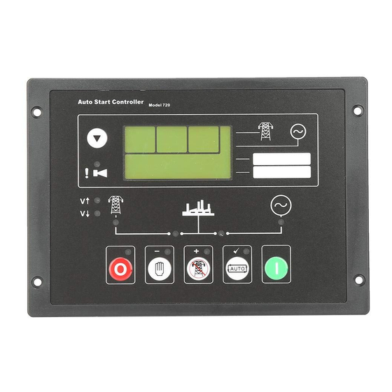
Model 720 Configuration and installation instructions
ACCESSING THE CONFIG EDITOR
Press the Stop/Reset
and Info
simultaneously.
The LED beside the AUTO button will
flash continuously to indicate that
configuration mode has been entered.
The first configuration
setting is displayed:
From the configuration table, this example is
displaying Start Delay (parameter 0). It is currently
set to 5 seconds.
EDITING A PARAMETER
Enter the editor as described above.
Press + / - to scroll through the parameters to
the one you want to change.
Press to enter edit
mode. The
symbol
will flash on the display
to
indicate
that
edit
mode has been entered.
Press + / - to change the value to the desired
parameter.
Press to save the value and exit edit mode for
this parameter.
The
symbol will be removed from the display
to indicate that edit mode has been exited.
To select another value to edit, press the + / -
buttons. Continuing to press the + and – buttons
will cycle through the adjustable parameters as
shown in the following lists.
NOTE: To exit the front panel configuration editor at any time, press the Stop/Reset
Ensure you have saved any changes you have made by pressing the button first
Deep Sea Electronics Plc.
Deep Sea Electronics inc.
Tel:+44 (0)1723 890099
Fax: +44 (0)1723 893303
LO CALL (from UK BT landlines) :
TOLL FREE (USA only) : Tel: 1 866 636 9703
Telephone 0845 260 8933
Email: dsesales@deepseausa.com
Email: support@deepseaplc.com
Web: www.deepseaplc.com
SETTINGS
Factory default settings are in bold italicised text.
buttons
Timers
0 - Start Delay
1 - Preheat
2 - Cranking Time
3 - Crank Rest Time
4 - Safety On Delay
5 - Warm Up Time
6 - Gen transient delay
7 – Return Delay
8 - Cooling Time
9 - ETS Hold Time
10 - Fail To Stop Delay Time
11 - Low DC Voltage Alarm Delay
NOTE:- Setting a timer to 0 will disable it
Generator
12 - Under Frequency
13 - Loading Frequency
14 - Over Frequency
15 - Loading Voltage
16 - Over Current Alarm
17 - Over Current Alarm Type
Engine
18 - Low DC Voltage Alarm
19 - Charge Fail Voltage Alarm
Fixed Input settings
20 - Low Oil Pressure
21 - High Engine Temperature
22 - Remote Start /
Simulated Mains input
Deep Sea Electronics Plc.
Phone: +1 (815) 316-8706
(Far East)
Fax: +1 (815) 316- 8708
Tel:+66 2 670 6228
Fax: +66 2 678 3028
Email: support@deepseaplc.com
Web: www.deepseausa.com
Web: www.deepseaplc.com
053-005
ISSUE 2
0-60m (5s)
0-60s (0s)
3-60s (10s)
3-60s (10s)
8-60s (8s)
0-10m (0s)
0-10s (0s)
0-60m (30s)
0-30s (1m)
0-60s (0s)
10-60s (60s)
0-60m (5m)
(where applicable)
0-60Hz (40Hz)
20-60Hz (47Hz)
50-72Hz (57Hz)
50-333V (212V)
50-120% (110%)
0 - Warning
1 - Shutdown
2 - Electrical Trip
0-25V (8V)
0-25V (8V)
5-150PSI (15 PSI)
90-150 C (95 C)
0 - Remote start
close to activate
1 - Remote start
open to activate
2 - Simulated mains
close to activate
3 - Simulated mains
open to activate
button.
Advertisement

Subscribe to Our Youtube Channel
Related Manuals for Deep Sea Electronics Plc 720


Summary of Contents for Deep Sea Electronics Plc 720
- Page 1 TYPICAL WIRING DIAGRAM ISSUE 2 D E E P S E A E L E C T R O N I C S Model 720 Configuration and installation instructions ACCESSING THE CONFIG EDITOR SETTINGS Factory default settings are in bold italicised text.
- Page 2 Factory default settings are in bold italicised text. Factory default settings are in bold italicised text. Auxiliary Input settings Misc LCD Indicators 23 - Auxiliary Input 1 0 - Delayed, warning close to activate 29 - LCD indicator 1 0 - Unused 31 - Full Load Current 5-6000A (500A) Rating...
Need help?
Do you have a question about the 720 and is the answer not in the manual?
Questions and answers