
Related Manuals for Technibel AOF Series


Summary of Contents for Technibel AOF Series
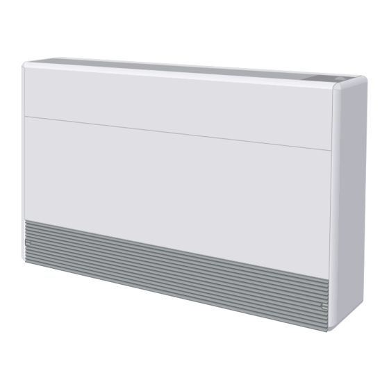
- Page 1 NOtice d’iNstALLAtiON iNstALLAtiON iNstRUctiONs (Etiquette signalétique) (Data label) AOF 15 AOF 25 AOF 55 cLiMAtiseUR MONOBLOc A cONdeNsAtiON PAR eAU siNGLe PAcKAGed ROOM AiR cONditiONeR WitH WAteR cOOLed cONdeNseR Octobre 2013 10 11 589 - F.GB - 01...
-
Page 2: Table Of Contents
MARKING This product marked conforms to the essential requirements of the Directives: - Low voltage no. 2006/95/EC. - Electromagnetic Compatibility no. 2004/108/EC. NOTE: This symbol mark and recycle system are applied only to EU countries and not applied to the countries in the other area of the world. -
Page 3: Generalities
1 - GENERALITIES 1.1 - GENERAL SuPPLY CoNDITIoNS • Generally speaking, the material is transported at the consignee’s risk. • The consignee must immediately provide the carrier with written reserves if he finds any damage caused during transport. 1.2 - RECoMMENDATIoNS •... - Page 4 2.2 - DESCRIPTIoN 1 - Discharge grille 12 - Electrical box 21 - Fan 2 - Removable panel 13 - Rotary switch 22 - Pressure tap Low Pressure 3 - Front panel 14 - Thermostat 23 - Pressure tap High Pressure 4 - Inlet grille 15 - Hermetic compressor...
-
Page 5: Installation
3 - INSTALLATIoN • When mounting the appliance, it is advisable to remove its cabinet for all handling operations. • If necessary, remove the fan assembly too. IMPoRTANT: During the installation of the unit, it is important to handle it with care in order not to damage the cabinet (deformation and looseness of the metal sheets) and the refrigerant pipes (displacement of copper pipes). - Page 6 3.4 - MouNTING Pressings acting as • The device must be installed in vertical position and level. It must feet always be installed fastened (to the floor or on a wall mounting). Adhesive side • For assembly on a wall mounting, refer to the accessories chapter for the mounting to be used.
-
Page 7: Connections
4 - CoNNECTIoNS 4.1 - REFRIGERANT CoNNECTIoN • No connection to the refrigerant circuit is to be carried out. The apparatus is ready to operate. 4.2 - WATER CoNNECTIoN • Thread the pipes through the knockout, after positioning the plastic profile provided on the edge of the sheet. •... - Page 8 5.2 - DISCoNNECToR (compulsory for connection to town water) • K 60 L 110 Z . 5.3 - WATER CoNNECTIoN HoSES • K 60 L 047 Z: 0.50 m long, female coupling Ø 3/4”. • K 60 L 048 Z: 1 m long, female coupling Ø 3/4”. 5.4 - REMoTE CoNTRoL A - Mounting / Installation •...
-
Page 9: Starting Up
C - Connections with automatic remote control - Code K 60 D 025 Z K 60 D 025 Z Phase Neutral Cooling Heating S1: On/Off switch. Air temperature sensor S2: Fan speed selector. (if used) K 60 D 028 Z or K 60 D 033 Z S3: Temperature setting knob. -
Page 10: Maintenance Instructions
7 - MAINTENANCE INSTRuCTIoNS IMPoRTANT NoTE • Before doing any work on the installation, make sure it is switched off and all power supplies locked out. • Also check that the capacitors are discharged. • Any work must be carried out by personnel qualified and authorised to work on this type of machine. •... -
Page 11: Electrical Diagrams
8 - WIRING DIAGRAMS Symbols of components Colours of wires Room thermostat Blue Blue / White Red / Grey Antifrost thermostat Grey Red / White M1 capacitor Purple White M2 capacitor Purple / White Filter capacitor Brown High pressure pressostat Brown / Red Black Compressor contactor... - Page 12 WIRING DIAGRAM - AoF 55 - 230 / 1 / 50 10 05 305 - 09 Note 1 Power supply 230V / 1 / 50Hz S2 S3 S4 HP> Note 1: Speeds connection Electric heater (accessory) S S1 S3 S4 0 0 0 0 0 0 L 1 2 3 4 5 6 7 1 0 1 0 1 0...
- Page 16 Par souci d'amélioration constante, nos produits peuvent être modifiés sans préavis. Due to our policy of continuous development, our products are liable to modification without notice. Z.I. Route départementale 28 CS 40131 Reyrieux 01601 TRévoux Cedex FRanCe Tél. 04 74 00 92 92 - Fax 04 74 00 42 00 Tel.
Need help?
Do you have a question about the AOF Series and is the answer not in the manual?
Questions and answers