Table of Contents
Advertisement
Quick Links
CONTENTS
GENERAL . . . . . . . . . . . . . . . . . . . . . . . . . . . . . . . . 1
VERTICAL UNIT INSTALLATION . . . . . . . . . . . . . . 2
Unit . . . . . . . . . . . . . . . . . . . . . . . . . . . . . . . . . . . . 2
Step 2 - Make Air Connections . . . . . . . . . . . . . . 2
Step 3 - Connect Piping . . . . . . . . . . . . . . . . . . . 3
Enclosure Installations) . . . . . . . . . . . . . . . . . . 3
Step 5 - Install Carrier Enclosures . . . . . . . . . . . 3
Runouts . . . . . . . . . . . . . . . . . . . . . . . . . . . . . . . . 3
ment As Required . . . . . . . . . . . . . . . . . . . . . . . . 4
Step 8 - Balance System . . . . . . . . . . . . . . . . . . 6
(Unit-Mounted or Wall-Mounted
Thermostat) . . . . . . . . . . . . . . . . . . . . . . . . . . . . 7
Base Unit Not in Carrier Enclosure . . . . . . . . . . . . 7
Base Unit in Carrier Enclosure . . . . . . . . . . . . . . . 7
Coil Reversal . . . . . . . . . . . . . . . . . . . . . . . . . . . . . . 8
GENERAL
These units are controlled by varying water flow through coil.
Follow installation steps in sequence suggested. Each step in-
cludes figure(s) and procedures required for a specific stage
of installation.
Set up a sample installation to familiarize all trades with their
specific job function.
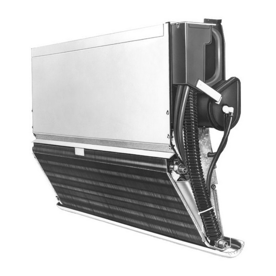
See Fig. 1 for the Proposition 65 warning label. See Fig. 2
and 3 for 36SV,SL base units.
Manufacturer reserves the right to discontinue, or change at any time, specifications or designs without notice and without incurring obligations.
Catalog No. 04-53360009-01
Installation Instructions
Printed in U.S.A.
Form 36S-1SI
Induction Air Terminals
(Bypass and Water Control)
WARNING
!
This product can expose you to chemicals
including Acrylonitrile, which is known to the
State of California to cause cancer. For
more information, go to
www.P65Warnings.ca.gov
AVERTISSEMENT
!
Ce produit peut vous exposer à des
agents chimiques, y compris l'acrylonitrile,
que l'État de Californie reconnaît comme
cancérigènes. Pour plus d'informations,
veuillez consulter
www.P65Warnings.ca.gov
ADVERTENCIA
!
Este producto puede exponerlo a productos
químicos que incluyen acrilonitrilo, que
el estado de California considera que
causa cáncer. Para más información visite
www.P65Warnings.ca.gov
Fig. 1 - Proposition 65 Warning Label
RETURN
SUPPLY
CONDENSATE
PAN
Fig. 2 - 36SV Base Unit
Pg 1
9-18
36S
PRIMARY AIR INLET
Replaces: 36R,S-1SI
Advertisement
Table of Contents

Subscribe to Our Youtube Channel
Related Manuals for Carrier 36S


Summary of Contents for Carrier 36S
- Page 1 Base Unit Not in Carrier Enclosure ... . 7 causa cáncer. Para más información visite Base Unit in Carrier Enclosure ....7 www.P65Warnings.ca.gov Coil Reversal .
-
Page 2: Vertical Unit Installation
Base Unit (see Fig. 4) Determine required length of mounting strip. Allow for length of enclosures and runouts to be used. Maximum unsupported length of Carrier enclosures is 2-in. on either side. Locate strip per job prints. Install straight and level using field-supplied fasteners through alternate and end holes. -
Page 3: Step 3 — Connect Piping
Step 3 — Connect Piping (see Fig. 6) If coil requires reversing, see Coil Reversal (page 8). Remove burrs and chips from all joints. Locate piping as shown. Piping may run behind 36S units. Connect water lines to coil. (Bottom coil connection is recommended for supply.) -
Page 4: Ment As Required
Step 7 — Install Enclosure and Runout Arrangement As Required Use end frame as template when drilling holes on unit enclo- sure side panels. Tap runout enclosure lightly to ensure tight fit in end frame slots. COLUMN-TO-COLUMN ARRANGEMENT (SEE FIG. 10) Drill two -in. -
Page 5: Column-To-Column With Shelving
COLUMN-TO-COLUMN WITH SHELVING (SEE FIG. 11) Attach end frame to unit enclosure with two No. 8 sheet metal screws (field-supplied). Drill two -in. holes for attaching runout. Cut runout enclosure, back panel, and shelving to desired ENCLOSURE WITH SINGLE OR DUAL RUNOUT (SEE length. -
Page 6: Step 8 — Balance System
Fig. 12 — Enclosure with Single or Dual Runout Fig. 13 — Single or Dual Runout (with Kickstrip) SINGLE OR DUAL RUNOUT WITH KICKSTRIP (SEE FIG. 13) Drill one -in. hole for attaching runout. Cut runout enclosure and kickstrip to desired length; join with No. -
Page 7: Base Unit Not In Carrier Enclosure
Level unit, using drain pan as reference. (Unit-Mounted or Wall-Mounted Thermostat) Make air connections (see Vertical Unit Installation, Base Unit Not in Carrier Enclosure (see Fig. 15) Step 2). Remove unit from carton. Remove protective packing. Make piping connections (see Vertical Unit Installation, Remove Z bars from shipping position. -
Page 8: Coil Reversal
Reassemble coil to unit; re-install condensate pan. Fig. 17 — Coil Reversal © Carrier Corporation 2018 Manufacturer reserves the right to discontinue, or change at any time, specifications or designs without notice and without incurring obligations. Catalog No. 04-53360009-01 Printed in U.S.A.
Need help?
Do you have a question about the 36S and is the answer not in the manual?
Questions and answers