Advertisement
Quick Links
Installation Instructions
Model LVM
Live Voice Module
INTRODUCTION
OPERATION
Controls and Indicators
P/N 315-034090-11
The Model LVM Live Voice Module from Siemens
Industry, Inc. provides firefighters with a means of
sending live voice messages to specified audio
zones. The LVM has a push-to-talk switch on the
microphone, as well as a retractable coiled cord.
Both the push-to talk switch and the microphone
are supervised. The LVM has a built-in speaker to
preview active tones and messages. Each DAC-
NET in the system (with an LPB) supports up to
five LVMs. Additional LVMs may be
connected remotely using the RNI.
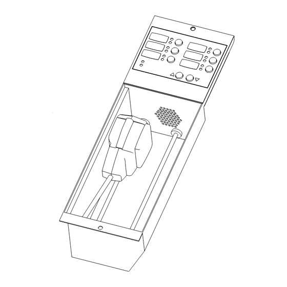
The front panel of the LVM contains
six switches and six pairs of LEDS.
Each pair contains one bi-color (red/
green) and one yellow LED. The
functions of the switches and LEDs
are programmed using the Zeus Tool
(Refer to the Zeus Quick Start Guide,
P/N 315-033875). All LEDs can be
programmed ON, OFF , or FLASHING.
These switches are used for manual
control of the voice system.
The functions of the remaining LEDs and push buttons are defined as follows:
PREANNOUNCE TONE
READY TO PAGE
MONITOR VOLUME
Figure 1
LVM Live Voice Module
(Yellow)
When illuminated, indicates that the
preannounce tone is active at the
speakers.
(Green)
When illuminated, indicates that all
selected zones are ready to be paged.
These two pushbuttons increase or
decrease the volume of the speaker on
the LVM.
Building
Building
Building T T T T T ec
Building
Building
Siemens
Siemens Industry
Siemens
Industry, , , , , Inc.
Industry
Industry
Siemens
Siemens
Industry
ec
ec
echnologies Di
ec
hnologies Division
hnologies Di
hnologies Di
hnologies Di
vision
vision
vision
vision
Inc.
Inc.
Inc.
Inc.
Advertisement

Related Manuals for Siemens LVM


Summary of Contents for Siemens LVM
- Page 1 Industry, Inc. provides firefighters with a means of sending live voice messages to specified audio zones. The LVM has a push-to-talk switch on the microphone, as well as a retractable coiled cord. Both the push-to talk switch and the microphone are supervised.
- Page 2 LVM Cable Connections, Diagnostics and Address Switches After setting the address, label each switch or LED. When viewed from the front panel of the LVM, the labels are on the left and the control switches and LEDs are on the right.
- Page 3 CAN module or P3 on the CC-5/CC-2 or P4 on the RNI. A 24 inch long 10 wire audio cable, P/N 555-134260, connects the LVM to P4 on the CC-5/CC-2, or JP6 on the PMI, or J1 on the PMI-2 or P1 on the RNI. (Refer to Figure 5.) Make sure that all cables seat fully into their connectors.
- Page 4 • Cable connections for the LVM are shown in the following table and in Figures 5 and 6. , . n , . n TO FMT TO CC-5/-2, PMI/PMI-2 OR RNI* TO NEXT CAN MODULE TO CC-5/-2 OR RNI* ERROR...
Need help?
Do you have a question about the LVM and is the answer not in the manual?
Questions and answers