
Related Manuals for wtw System 2020 XT


Summary of Contents for wtw System 2020 XT
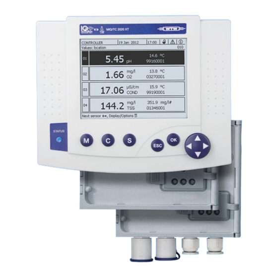
- Page 1 Operating Manual IQ S ENSOR System 2020 XT C ONNECT Modular multi-parameter measuring system Controller MIQ/MC2 ba75970e01 10/2012...
- Page 2 Copyright © 2016 Xylem Analytics Germany GmbH Printed in Germany.
-
Page 3: Table Of Contents
Components of the system 2020 XT ........ - Page 4 Contents System 2020 XT C ONNECT 3.5.3 Distributed mounting of MIQ modules ....... . .3-21 3.5.4...
- Page 5 System 2020 XT C Contents ONNECT Status info of sensors and outputs .........4-29 General course when calibrating, cleaning, servicing or repairing an IQ sensor .
- Page 6 Contents System 2020 XT C ONNECT 6.2.1 General information ..........6-6 6.2.2...
- Page 7 System 2020 XT C Contents ONNECT 10.4.2 Adding and replacing IQ sensors ........10-8 10.4.3 Adding and replacing MIQ output modules .
- Page 8 Contents System 2020 XT C ONNECT 0 - 6 ba75970e01 10/2012...
-
Page 9: Overview
System 2020 XT C Overview ONNECT Overview How to use this system operating manual Structure of the IQ S operating IQ Sensor Net Operating Manual ENSOR manual System Operating Manual (Ring Binder) IQ Sensor MIQ Module MIQ Terminal Operating Operating... -
Page 10: The Iq Sensor Net System2020 Xt
Overview System 2020 XT C ONNECT The IQ S system2020 XT ENSOR 1.2.1 Structure of the system The IQ S is a modular measuring system for online analysis. ENSOR Modular means that the essential functional units of the measuring sys- tem are distributed in components that can be individually compiled for special applications. -
Page 11: Functions In The Iq Sensor Net
System 2020 XT C Overview ONNECT PC + IQ Software Pack CONNECT SmartPhone Tablet PC Landline / GSM / Radio Modbus Data Router RS 485 transfer device PROFIBUS USB flash drive Radio Ethernet MIQ/2-MOD MIQ/2-PR Radio module Radio module 100 m Interface Controller MIQ/MC2 ... -
Page 12: Possible Ways To Communicate With The Iq Sensor Net
Overview System 2020 XT C ONNECT Function Component Data communication (Modbus) MIQ/MC2-MOD MIQ/2-MOD Data logger IQ Software Pack C ONNECT Web server MIQ/MC2 Differential sensor System Frequency output Relay output module Limit monitor Relay output module Calibration history System List of outputs, list of sensors... - Page 13 System 2020 XT C Overview ONNECT Available func- Direct Viewing/ Viewing/ System con- Calibration tions actions via transmitting transmitting figuration, data, the terminal current logged data: • save load user inter- data: Measured view view trans- • • face Measured...
-
Page 14: Components Of The System 2020 Xt
(e.g. temperature). In the System 2020 XT, digital WTW single sensors and multiple sensors can be used: Single sensors provide a main measured value and normally a sec- ondary measured value (example: TriOxmatic 700 IQ D. - Page 15 System 2020 XT C Overview ONNECT Each current output, relay output and valve output occupies an out- put channel in the IQ S . The available output channels ENSOR can be assigned to outputs arbitrarily. Power supply modules for power supply ...
- Page 16 Overview System 2020 XT C ONNECT Connecting MIQ modules There are two basic mounting variants for connecting the MIQ modules: Stack mounting - permanent mechanical and electrical connection. The housings of the MIQ modules are permanently mounted on one another to form a stack.
-
Page 17: Miq Modules
System 2020 XT C Overview ONNECT 1.2.5 MIQ modules Some of the IQ S components are so-called MIQ modules ENSOR with different functions. All MIQ modules have a standard housing with the following features (Fig. 1-4): P o w Fig. 1-4... - Page 18 Overview System 2020 XT C ONNECT Common characteristics Module lid with hinge of the MIQ modules Due to its wide opening angle, the lid provides a large space for working inside the module (e.g. for connecting lines to the terminal strip).
-
Page 19: Miq/Mc2 Controller
System 2020 XT C Overview ONNECT controller 1.2.6 MIQ/MC2 The MIQ/MC2 controller does the following jobs: Control and monitoring of all IQ sensors Control and monitoring of all current and relay outputs Continuous diagnosis of the system, i.e. the information and error... -
Page 20: Terminals
MIQ/TC 2020 XT, configured as a terminal PC Terminal C , connected to a PC via the Ethernet inter- ONNECT face. The system System 2020 XT C is not compatible ONNECT with the no longer available terminals MIQ/T2020 and MIQ/ T2020 PLUS. -
Page 21: Behavior Of The Iq Sensor Net If A Components Fails
System 2020 XT C Overview ONNECT 1.2.9 Behavior of the IQ S if a components fails ENSOR If the operating voltage is too low, the LEDs on the MIQ modules extinguish. If active components (e.g. sensors or output modules) cannot be contacted, an entry is made in the log book. -
Page 22: Availability Of The System
Overview System 2020 XT C ONNECT 1.2.10 Availability of the system The IQ S was optimized to achieve a very high availability. ENSOR The high availability is achieved through The two-wire connection technique that is not interference-prone The digital signal transmission resulting from this ... - Page 23 System 2020 XT C Overview ONNECT 1.2.11 Compatibility of the MIQ/MC2 (System 2020 XT C ) with ONNECT components of an existing IQ S system ENSOR The MIQ/MC2 controller uses modern network engineering (Ethernet) for communication with the IQ S system.
- Page 24 Overview System 2020 XT C ONNECT 1 - 16 ba75970e01 10/2012...
-
Page 25: Safety
System 2020 XT C Safety ONNECT Safety Safety information 2.1.1 Safety information in the operating manual This operating manual provides important information on the safe oper- ation of the product. Read this operating manual thoroughly and make yourself familiar with the product before putting it into operation or working with it. -
Page 26: Safe Operation
Safety System 2020 XT C ONNECT Safe operation 2.2.1 Authorized use The authorized use of the System 2020 XT C consists of its use ONNECT as a sensor in the IQ S . Only the operation and running of ENSOR... - Page 27 System 2020 XT C Safety ONNECT Special user qualifications The following installation activities may only be performed by a quali- fied electrician: Connection of the MIQ/PS power supply module to the power line (see MIQ/PS module manual). Connection of external, line voltage-carrying circuits to relay con- tacts (see module manual of the relay output module).
- Page 28 Safety System 2020 XT C ONNECT 2 - 4 ba75970e01 10/2012...
-
Page 29: Installation
System 2020 XT C Installation ONNECT Installation Scopes of delivery MIQ modules standard MIQ module MIQ/MC2 with the following interfaces scope of delivery – USB – Ethernet – optional: MODBUS or PROFIBUS Accessory set, including: – 4 x cable glands (clamping range 4.5-10 mm) with seals and blind plugs –... -
Page 30: Basics Of The Installation
Installation System 2020 XT C ONNECT Basics of the installation 3.3.1 System planning Overview of planning Start steps Fundamentals of planning - Number and types of required sensors - Measuring locations to be designed - Number of required operating locations - Distances - Infrastructure, process environment etc. -
Page 31: Basic Requirements For Optimum Installation
System 2020 XT C Installation ONNECT Basic requirements for optimum installation 3.4.1 General information The IQ S supplies all components with low voltage as well ENSOR as digital communication via a shielded 2-wire line. Due to this characteristic, the following factors must be taken into... - Page 32 Installation System 2020 XT C ONNECT Power requirement of Component Power requirement [W] IQ S ENSOR IQ sensors components ® SensoLyt 700 IQ (SW) ® TriOxmatic 700 IQ (SW) ® TriOxmatic 701 IQ ® TriOxmatic 702 IQ ® 70x IQ (SW) ®...
- Page 33 System 2020 XT C Installation ONNECT Determining the number From the value determined for the power requirement, determine the of MIQ power supply number of the MIQ power supply modules as follows: modules Total power requirement P Number of MIQ power supply modules ≤...
-
Page 34: Effect Of The Cable Length
Installation System 2020 XT C ONNECT 3.4.3 Effect of the cable length The length of the cables in the IQ S affects ENSOR the operating voltage available for a component the quality of data transmission. All information applies to SNCIQ cable material only. As... - Page 35 System 2020 XT C Installation ONNECT Example The following figure shows the length of the cable section L made up of the partial lengths L1, L2 and L3 as the cable section L4 is shorter than L = L1 + L2 + L3...
- Page 36 Installation System 2020 XT C ONNECT Checking the power Determine the length of the cable section for the planned supply installation. Determine the sum of the power consumption of all consumers along the cable section (including IQ sensors). Enter both determined values as a point in the following dia- gram.
- Page 37 System 2020 XT C Installation ONNECT Example Problem: Consumers with a total power requirement of 9 W are positioned on a cable section of 650 m. Is the power supply with one power supply module sufficient? At which point must a further power supply module...
-
Page 38: Optimum Installation Of Miq Power Supply Modules
Installation System 2020 XT C ONNECT 3.4.4 Optimum installation of MIQ power supply modules Basic rules Install the MIQ power supply modules as near as possible to the IQ S components with the highest power consumption. ENSOR This also applies in the case of several MIQ power supply modules in the system. - Page 39 System 2020 XT C Installation ONNECT which MIQ modules are installed must be connected to the local po- tential equalization system and the grounding system or must be in- dividually sufficiently grounded locally according to the codes of practice. For the individual grounding of the measuring point the mounting...
- Page 40 Installation System 2020 XT C ONNECT – The shield of SNCIQ or SNCIQ-UG cables can be connected to the local potential equalization with a gas overvoltage arrester. Shielding terminals (e.g. of the PROFIBUS system) have to be used for the contacting of the shield. The shield of the cable must not be opened under any circumstances.
-
Page 41: Connecting System Components
System 2020 XT C Installation ONNECT Connecting system components 3.5.1 General information The IQ S system components are connected to form a func- ENSOR tioning unit in the following ways: Stacked mounting of MIQ modules Up to three MIQ modules can be installed and mechanically con- nected with one another to form a stack at a single location. -
Page 42: Stacked Mounting Of Miq Modules
Installation System 2020 XT C ONNECT 3.5.2 Stacked mounting of MIQ modules: Note For optimum stability, a maximum of three MIQ modules can be mount ed in any one stack. Only one MIQ power supply module may be mounted per module stack. - Page 43 System 2020 XT C Installation ONNECT Both installation variants are described below. To dismantle a module stack, proceed in the reverse order to mounting the stack. Variant 1: Stack expansion forwards Preparing the stack Back Front mounting MIQ module MIQ module...
- Page 44 Installation System 2020 XT C ONNECT Attach the contact base (pos. 5 in Fig. 3-5) on the front MIQ module with the two plastic tapping screws (pos. 6). On the front MIQ module, remove the two countersunk screws (pos. 7 in Fig. 3-5) and swing open the module lid.
- Page 45 System 2020 XT C Installation ONNECT Stacking the MIQ modules Fig. 3-7 MIQ modules (variant 1) Stacking the Fig. 3-8 Closing the enclosure (variant 1) Attach the prepared MIQ module to the lid of the back MIQ module. At the same time, ensure that the two clips on the front MIQ module click into place in the lid of the back MIQ module.
- Page 46 Installation System 2020 XT C ONNECT Close the lid of the front MIQ module and fix it with the two countersunk screws (pos. 7 in Fig. 3-8). Variant 2: stack expansion backwards Preparing the stack mounting Back Front MIQ module...
- Page 47 System 2020 XT C Installation ONNECT Mounting the contact base Fig. 3-10 Mounting the contact base (variant 2) Note Only use the plastic tapping screws supplied for attaching the contact base. They ensure the correct fit. Attach the contact base (pos. 6 in Fig. 3-10) on the front MIQ module with the two plastic tapping screws (pos.
- Page 48 Installation System 2020 XT C ONNECT Stacking the MIQ modules Fig. 3-12 MIQ modules (variant 2) Stacking the Fig. 3-13 Closing the housing (variant 2) Attach the prepared MIQ module to the back of the front MIQ module. At the same time, ensure that the two clips on the front MIQ module click into place in the lid of the back MIQ module.
-
Page 49: Distributed Mounting Of Miq Modules
System 2020 XT C Installation ONNECT Close the back MIQ module and fix it with the two countersunk screws (pos. 5 in Fig. 3-13). 3.5.3 Distributed mounting of MIQ modules General information The following IQ S cables can be used for distributed... - Page 50 Installation System 2020 XT C ONNECT Preparing the cable ends Cut off the cable to the required length. Remove approx. 45 mm of cable insulation (in the case of the SNCIQ/UG earth cable, remove both the inner and outer insu- lation).
- Page 51 System 2020 XT C Installation ONNECT SENSORNET 1 SENSORNET 2 SENSORNET 2 SENSORNET 1 SNCIQ SACIQ SNCIQ/UG Fig. 3-15 Connecting cables to the MIQ module Screw the cable gland (pos. 1 in Fig. 3-15) with the sealing ring (pos. 2) into the module housing.
- Page 52 Installation System 2020 XT C ONNECT Fig. 3-16 Closing the cable opening Screw the remaining cable glands with the sealing rings into the remaining free openings and close them with the enclosed blind plugs (pos. 4 in Fig. 3-16) and tighten the cap nut (pos. 3) if they are not used.
-
Page 53: Connecting Iq Sensors
System 2020 XT C Installation ONNECT 3.5.4 Connecting IQ sensors Materials required 1 x SACIQ connection cable (see chapter 12 A CCESSORIES AND OPTIONS 1 x cable gland with seal The module end of the connection cable already has the sheath removed in the factory and all the wires are fitted with wire end sleeves. - Page 54 Installation System 2020 XT C ONNECT cur. Remove the protective caps from the plug connections of the IQ sensor and SACIQ sensor connection cable and keep them Connecting the sensor to safe. the connection cable Plug the socket of the SACIQ sensor connection cable onto the plug head connector of the IQ sensor.
-
Page 55: Installation Of The Miq Modules At The Installation Location
System 2020 XT C Installation ONNECT Installation of the MIQ modules at the installation location 3.6.1 General information The IQ S system has a comprehensive program of mount- ENSOR ing accessories, which can be used to adapt the installation to the most varied requirements. -
Page 56: Mounting On A Mounting Stand With The Ssh/Iq Sun Shield
Installation System 2020 XT C ONNECT 3.6.2 Mounting on a mounting stand with the SSH/IQ sun shield Materials required SSH/IQ sun shield (see chapter 12 A CCESSORIES AND OPTIONS Tools 4 mm set screw wrench Phillips screw driver. - Page 57 System 2020 XT C Installation ONNECT Premounting the ISO blind nuts Fig. 3-19 Mounting the sun shield: Premounting the ISO blind nuts Remove the two countersunk screws (pos. 5 in Fig. 3-19) and swing open the module lid. Insert the cheese-head screws (pos. 6 in Fig. 3-19) with the plastic washers in the drilled mounting holes and loosely screw in the ISO blind nuts (pos.
-
Page 58: Mounting Under The Sd/K 170 Sun Shield
Installation System 2020 XT C ONNECT Position the MIQ module on the sun shield and fix it into place with the two screws (pos. 6 in Fig. 3-19). Close the module lid and fix it with the two countersunk screws (pos. - Page 59 System 2020 XT C Installation ONNECT Mounting the MIQ module under the sun shield Fig. 3-21 Mounting the MIQ module on the SD/K 170 sun shield Remove the two countersunk screws (pos. 1 in Fig. 3-21) and swing open the module lid.
-
Page 60: Panel Mounting
Installation System 2020 XT C ONNECT 3.6.4 Panel mounting The space required on the panel for a module stack is given in the dimension drawings in section 11.3. The front MIQ module of the preassembled module stack must be removed in order to install the stack. After the... - Page 61 System 2020 XT C Installation ONNECT Slightly unscrew the screws (pos. 2 and 3) of the two angle brackets (pos. 1 in Fig. 3-22), but do not remove them. Push in the two angle brackets - as shown in Fig. 3-22 - into the lateral guides of the MIQ module up to the stop.
-
Page 62: Top Hat Rail Mounting
Installation System 2020 XT C ONNECT 3.6.5 Top hat rail mounting Materials required THS/IQ kit for top hat rail mounting (see chapter 12 A CCESSORIES AND OPTIONS Tools Phillips screw driver. Mounting the MIQ module on a top hat rail... -
Page 63: Electrical Connections: General Instructions
System 2020 XT C Installation ONNECT Electrical connections: General instructions Cable glands All electric cables are fed from below via prepared openings in the enclosure of the MIQ modules. Cable glands with different clamping ranges are included with most MIQ modules to provide sealing between the cable and enclosure as well as for strain relief. -
Page 64: Connecting The Voltage Supply
Installation System 2020 XT C ONNECT General installation Observe the following points when attaching connecting wires to the instructions terminal strip Shorten all the wires to be used to the length required for the instal- lation Always fit all the ends of the wires with wire end sleeves before con- necting them to the terminal strip ... -
Page 65: Ethernet Connection In Case Of Outdoor Installation
System 2020 XT C Installation ONNECT Ethernet connection in case of outdoor installation When plugged in, the RJ45 socket is not sufficiently protected against moisture. With outdoor installation, the Ethernet cable must therefore be clamped directly on the PCB of the MIQ/MC2 controller to ensure a safe Ethernet communication. - Page 66 Installation System 2020 XT C ONNECT LSA terminal strip SHIELD CLAMP ENTHERNET CABLE Fig. 3-25 Ethernet connection via terminal strip Strip the Ethernet cable for approx. 2 cm and untwist the Rx+, Rx-, Tx+ and Tx wires. Carefully slash the cable shield (foil + netting) lengthwise and put it backwards over the cable sheath (pos.
-
Page 67: Commissioning
System 2020 XT C Installation ONNECT 3.10 Commissioning 3.10.1 Topology and terminator switch For failure-free operation, the terminator switches (terminating resis- tors) must always be set to ON on two MIQ modules. On which mod- ules this has to be done can be taken from the topology of the... - Page 68 Installation System 2020 XT C ONNECT Example of determining The following figure shows the length of the main line L made up of the the main line partial lengths L1, L2 and L3 as the cable section L4 is shorter than L3:...
-
Page 69: Start Checklist And System Start
System 2020 XT C Installation ONNECT 3.10.2 Start checklist and system start Before starting the system, carry out the system check using the follow- ing checklist. Always carry out the check before the initial commissioning before any further commissioning if the system has been previously extended or modified. - Page 70 Installation System 2020 XT C ONNECT Initial start phase In the initial start phase, all IQ S components are automati- ENSOR cally registered on the MIQ/MC2 controller module and the terminal is initialized. The system then performs a self test. This process can take several seconds.
-
Page 71: Checking The Voltage Supply
System 2020 XT C Installation ONNECT 3.10.3 Checking the voltage supply This test should always be performed: after the initial commissioning after any system extension or modification. This test checks the power supply and the communication of the com- ponents after the system has been started. - Page 72 Installation System 2020 XT C ONNECT . 10 C ER r. 9 r. - N Fig. 3-31 Voltage LED on the MIQ module You can measure the voltage that is actually available at the MIQ modules or IQ sensors (see section 10.2.2).
-
Page 73: System Extension And Modification
System 2020 XT C Installation ONNECT 3.11 System extension and modification 3.11.1 General information The modular structure of the IQ S system makes it easy to ENSOR carry out subsequent extensions and modifications. The system auto- matically identifies new active modules and includes them in the list of modules. - Page 74 Installation System 2020 XT C ONNECT If a new component is not included, the maximum number of datasets (active and inactive datasets) may be exceeded. The maximum number of datasets for IQ sensors is 20. For MIQ output modules, the maximum number of datasets (active and inactive datasets) is 48.
-
Page 75: Operation
System 2020 XT C Operation ONNECT Operation MIQ/MC2 controller The MIQ/MC2 controller is the control unit of the IQ S ENSOR Terminal The terminal is the operating unit of the IQ S ENSOR You can install the following terminal components: ... -
Page 76: Overview Of The Operating Elements
Operation System 2020 XT C ONNECT 4.2.1 Overview of the operating elements This section provides basic information on the operation of the IQ S systems using the MIQ/TC 2020 XT (configured as a ENSOR terminal). General key symbols are used for all operating steps in this operating manual. -
Page 77: Display
System 2020 XT C Operation ONNECT 4.2.2 Display The display contains the following information: Fig. 4-2 View of the display Name of the display Name of the terminal alternating with the controller function (CONTROLLER or BACKUP CONTROLLER) Date Time User authorization:... - Page 78 Operation System 2020 XT C ONNECT Error symbol If the error symbol flashes, a new or unacknowledged error message is present in the log book that requires immediate action (see section 4.6.3). Info symbol If the info symbol flashes, new or unacknowledged information is present in the log book (see section 4.6.3).
- Page 79 System 2020 XT C Operation ONNECT Measured value display The measured value display contains the following information for each IQ sensor/differential sensor: Fig. 4-3 Display - measured value display Consecutive numbering of the measured values Main measured value Unit and parameter of the main measured value Name of the sensor (to enter name: see section 5.4.1...
-
Page 80: Keys
Operation System 2020 XT C ONNECT 4.2.3 Keys Function <M> Display measured values <C> Start calibration of the IQ sensor selected in the measured value dis- play Settings <S> Open the menu <ESC> Change to the higher menu levels or abort entries without storing them <OK>... -
Page 81: General Operating Principles
System 2020 XT C Operation ONNECT General operating principles The operation of the IQ S is standardized and user-friendly. ENSOR Select an item with the arrow keys <> – Highlight individual elements in menus, lists and tables, e.g. menu entries, list elements, columns or fields –... -
Page 82: Navigating In Menus, Lists And Tables
Operation System 2020 XT C ONNECT 4.3.1 Navigating in menus, lists and tables Settings Using <S>, open the menu. Menus appear in the form of a list on the display, e.g. the tings menu shown here. Fig. 4-4 Settings System settings Select a menu item (e.g. -
Page 83: Entering Texts Or Numerals
System 2020 XT C Operation ONNECT 4.3.2 Entering texts or numerals You can assign names to IQ sensors, MIQ output modules, terminals and locations. Example: Entering a sensor name: Settings Using <S>, open the menu. Edit list of sensors Select the menu item with <>. - Page 84 Operation System 2020 XT C ONNECT Fig. 4-6 Edit list of sensors The following letters, numerals and special characters can be entered: AaBb..Zz0..9µ%&/()+-=><!?_ °. Select a letter or numeral with <>. Confirm the letter with <OK>. The character appears behind the last letter.
- Page 85 System 2020 XT C Operation ONNECT Add a new character Select the character to be added with <> and con- firm with <OK>. Delete the last character Select the character with <> and confirm with <OK>. Adopt the name Select the character with <>...
-
Page 86: Access To The Iq Sensor Net With Active Access Control
Operation System 2020 XT C ONNECT Access to the IQ S with active access control ENSOR Access control is switched off in the delivery condition. No login to the IQ S is required. ENSOR As soon as an access control of any type is enabled, access to the IQ S is protected completely or partly. -
Page 87: Simple Access Control
System 2020 XT C Operation ONNECT 4.4.1 Simple access control A lock symbol is displayed if the simple access control is enabled and the system settings are locked. If a closed lock symbol is displayed, a message appears on the display of the IQ S... -
Page 88: Extended Access Control
Operation System 2020 XT C ONNECT 4.4.2 Extended access control If the extended access control is enabled (without instrument block), a symbol is displayed for the currently enabled access authorization. Crown: Administrator logged in, all functions allowed Tool: User with authorization for maintenance activities logged in (e.g. -
Page 89: Extended Access Control With Instrument Block
System 2020 XT C Operation ONNECT 4.4.3 Extended access control with instrument block If the extended access control with instrument block is enabled, only the IQ S logo is displayed on the terminal where the instru- ENSOR ment block was activated. -
Page 90: Display Of Current Measured Values
Operation System 2020 XT C ONNECT Display of current measured values Several options can be selected for displaying the measured values: Measured values (1 sensor) The measured value is shown numerically and as a bar graph on the Measured values (1 sensor) display (see section 4.5.1) -
Page 91: Displaying A Single Measured Value
System 2020 XT C Operation ONNECT 4.5.1 Displaying a single measured value The measured value is shown numerically and as a bar graph on the Measured values (1 sensor) display. Fig. 4-9 010 - Values: location -> Measured values (1 sensor) 4.5.2 Displaying four measured values... -
Page 92: Displaying Eight Measured Values
Operation System 2020 XT C ONNECT 4.5.3 Displaying eight measured values Up to eight measured values of IQ sensors or differential sensors are shown on the display at the same time. Fig. 4-11 010 - Values: location -> Measured values (8 sensors) - Page 93 System 2020 XT C Operation ONNECT 4.5.4 Displaying recorded measured values If the measured value recording has been activated for an IQ sensor (see section 5.10), the temporal course of the recorded measured val- ues can be displayed numerically and graphically.
-
Page 94: Displaying Recorded Measured Values
Operation System 2020 XT C ONNECT Displaying recorded Switch to the measured value display with <M>. measured values Select an IQ sensor with <>. Display/Options Using <OK>, open the menu. Select one of the display types with <> Monthly load of selected sensor ... -
Page 95: Transmitting Recorded Measuring Data To A Pc
System 2020 XT C Operation ONNECT 4.5.5 Transmitting recorded measuring data to a PC Recorded measured values can be transmitted to a PC via the Ethernet interface. For details on data transmission, see section 6. 4.5.6 Display of the measured values of a measurement location or... -
Page 96: Messages And Log Book
Operation System 2020 XT C ONNECT Messages and log book The IQ S continuously monitors the status of the entire sys- ENSOR tem. If the IQ S identifies system changes, a message ENSOR appears. New messages can be recognized by the flashing information symbol or error symbol on the display. - Page 97 System 2020 XT C Operation ONNECT Structure of the log book Fig. 4-14 310 - Log book of entire system Message category (error or info symbol) Module that triggered the message. system (controller) IQ sensor (number 01) IQ sensor (inactive, dataset deleted)
- Page 98 Operation System 2020 XT C ONNECT Structure of the message The message code consists of 6 characters and can contain numerals code and letters, e.g.: II2121. Type number Type Component code Category II2 121 Pos. Information Description 1 - 3...
-
Page 99: Viewing Detailed Message Texts
System 2020 XT C Operation ONNECT The detailed message text in the log book contains a pre- cise description of the message code and, if required, any further actions. The detailed message texts can also be found in the com- ponent operating manuals of the individual components. -
Page 100: Acknowledge All Messages
Operation System 2020 XT C ONNECT Acknowledge the message with <OK>. A tick appears in the log book entry. Exit the message text with <ESC>. Acknowledgment of a new message text in the log book marks the message as read. When all errors or information messages are acknowledged, the symbols no longer flash. -
Page 101: Calibration Data
System 2020 XT C Operation ONNECT Calibration data Details on calibration are given in the operating manual for the IQ sensor. Each calibration of IQ sensors that are able to be calibrated causes an entry to be made in the log book. Log book entries contain the following information: ... -
Page 102: Calibration History
Operation System 2020 XT C ONNECT 4.7.2 Calibration history The calibration history contains the detailed calibration data of the last calibrations. Call up the measured value display with <M>. Using <>, highlight a sensor and confirm with <OK>. Display/Options menu opens. -
Page 103: Status Info Of Sensors And Outputs
System 2020 XT C Operation ONNECT Status info of sensors and outputs The display of the instrument status provides a simple overview of the current modes of sensors (sensor info) and outputs in the IQ S ENSOR Settings Service List of all... -
Page 104: General Course When Calibrating, Cleaning, Servicing Or Repairing An Iq Sensor
Operation System 2020 XT C ONNECT General course when calibrating, cleaning, servicing or repairing an IQ sensor When an IQ sensor is calibrated, cleaned, serviced or repaired, the maintenance condition for the relevant IQ sensor should always be switched on. -
Page 105: Maintenance Condition Of Iq Sensors
System 2020 XT C Operation ONNECT 4.9.1 Maintenance condition of IQ sensors The following diagram gives you an overview of when an IQ sensor is in the maintenance condition. Maintanance Sensor condition ON cleaning Measured value Measured value manually active... -
Page 106: Switching On The Maintenance Condition
Operation System 2020 XT C ONNECT 4.9.2 Switching on the maintenance condition Switch on the maintenance condition manually when you want to clean, service or repair (remove and replace) an IQ sensor. Call up the measured value display with <M>. -
Page 107: Switching Off The Maintenance Condition
System 2020 XT C Operation ONNECT 4.9.3 Switching off the maintenance condition Call up the measured value display with <M>. Select the sensor you want to switch off the maintenance con- dition for with <>. The display of the sensor in the measured value display flashes. -
Page 108: Usb Interface
Operation System 2020 XT C ONNECT 4.10 USB interface The USB interface on the MIQ/MC2 can be used for the following actions: Save data of the IQ S to a USB memory device ENSOR (see section 4.10.1) Transmit data to a PC with the aid of a USB memory device (see section 4.10.2) - Page 109 System 2020 XT C Operation ONNECT Select the data to be saved with <>. Save configuration Measured data storage Log book Calibration history and confirm with <OK>. When saving the measured value memory only: A list of those sensors is displayed for which measure- ment data are stored .
-
Page 110: Transmitting Recorded Measurement Data To A Pc
Operation System 2020 XT C ONNECT Save Press <> to highlight the menu item and confirm with <OK>. The selected data will be stored to the USB memory device. 4.10.2 Transmitting recorded measurement data to a PC In the IQ S... -
Page 111: Software-Update For Iq Sensor Net
4.11 Software-Update for IQ S ENSOR With a Software-Update, you maintain the latest state of the instrument software for your IQ S system 2020 XT and all active com- ENSOR ponents. The update packet with the current instrument software for active... -
Page 112: Info On Software Versions
Operation System 2020 XT C ONNECT 4.11.1 Info on software versions The system informs you of the current versions of the software of the individual IQ S components. ENSOR Call up the measured value display with <M>. Settings Using <S>, open the menu. -
Page 113: Settings/Setup
(e.g. sensor, con- troller, terminal, output module) appear in the standard language, German. To activate the selected system lan- guage for this component, a software update of the compo- nent is required. Please contact WTW. 5 - 1 ba75970e01 10/2012... -
Page 114: Terminal Settings
Settings/setup System 2020 XT C ONNECT Terminal settings The available terminal settings depend on the terminal installed. The following terminals can be used: MIQ/TC 2020 XT, configured as a terminal PC Terminal C (see documentation on the ONNECT... -
Page 115: Editing The List Of Sensors
System 2020 XT C Settings/setup ONNECT Press <> and <OK> to enter the valid password and press <OK> to confirm. The setting is changed. Forgotten the password? You can display the valid pass- word on the screen (see section 14.1). -
Page 116: Changing The Display Position
Settings/setup System 2020 XT C ONNECT Fig. 5-3 Edit list of sensors Enter the name with <> and <OK> and confirm with <OK> (see section 5.4.1). 5.4.2 Changing the display position The numbering of the sensors is generated by the system. The order of... - Page 117 System 2020 XT C Settings/setup ONNECT Fig. 5-4 Edit list of sensors -> Set display position Set display position Using <>, select the menu item, and confirm with <OK>. A dialog window opens. Press <> to select the required number for the display position and confirm with <OK>.
-
Page 118: Erasing Inactive Sensor Datasets
Settings/setup System 2020 XT C ONNECT 5.4.3 Erasing inactive sensor datasets An inactive dataset for an IQ sensor arises if the controller receives no Error signals from a registered IQ sensor. The display appears on the measured value display instead of a measured value. Inactive datasets Edit list of sen can be recognized by a question mark, e.g. -
Page 119: Setting Up Iq Sensors/Differential Sensors
System 2020 XT C Settings/setup ONNECT Setting up IQ sensors/differential sensors 5.5.1 Creating a differential sensor A differential sensor is a virtual sensor. It shows the differential value of two IQ sensors that measure the same parameter and have the same settings. -
Page 120: Erasing A Differential Sensor
Settings/setup System 2020 XT C ONNECT 5.5.2 Erasing a differential sensor If a differential sensor is no longer required, it can be erased from the list of sensors. Settings Using <S>, open the menu. Using <> and <OK>, select and confirm the menu System settings Settings of sensors and diff. -
Page 121: Editing The List Of Outputs
System 2020 XT C Settings/setup ONNECT Settings Using <S>, open the menu. Using <> and <OK>, select and confirm the menu System settings Settings of sensors and diff. sensors item, -> Settings of sensors and diff. sensors display opens. Measuring range Using <>, highlight the... -
Page 122: Entering / Editing The Name Of An Output
Settings/setup System 2020 XT C ONNECT 5.6.1 Entering / editing the name of an output For the easier identification of the outputs, you can assign an individual Edit list of outputs name to each output in the display. Settings Using <S>, open the menu. - Page 123 System 2020 XT C Settings/setup ONNECT Fig. 5-10 Edit list of sensors 5 - 11 ba75970e01 10/2012...
-
Page 124: Erasing An Inactive Dataset For An Miq Output Module
Settings/setup System 2020 XT C ONNECT 5.6.2 Erasing an inactive dataset for an MIQ output module An inactive dataset for an MIQ output module arises if the system receives no signals from a registered MIQ output module. Inactive Edit datasets can be recognized by a question mark, e.g. "?01" in the list of outputs overview. -
Page 125: Output Links/Settings
System 2020 XT C Settings/setup ONNECT 5.6.3 Output links/settings The procedure and possible settings for linking outputs with sensors are given in the operating manual of the respective output module. Settings for a measurement location Primarily, the settings for a measurement location simplify the calibra- tion of IQ sensors if several IQ sensors of the same type are operated on the system. -
Page 126: Location Display
Settings/setup System 2020 XT C ONNECT Entering the name of a The name of the measurement location is displayed in the line with the measuring location name of the display. 15 characters are available for the name of the measurement location. -
Page 127: Alarm Settings
System 2020 XT C Settings/setup ONNECT Alarm settings 5.8.1 General information Under this menu item you can specify reactions on certain alarm events. An alarm event is when a certain measured value (limiting value) of a sensor is exceeded or undercut. You can configure up to 20 alarm events. -
Page 128: Setting Up / Editing Alarms
Settings/setup System 2020 XT C ONNECT 5.8.2 Setting up / editing alarms Settings Using <S>, open the menu. Using <> and <OK>, select and confirm the menu Alarm settings item, -> . Alarm link overview dialog window opens. Alarms that have already been set up have entries in the column. - Page 129 System 2020 XT C Settings/setup ONNECT Fig. 5-14 Select sensor for alarm link To set up a new alarm, select a sensor from the list with Set alarm link <> and confirm with <OK>. The display opens. Fig. 5-15 Set alarm link Edit the setting table.
- Page 130 Settings/setup System 2020 XT C ONNECT Alarm links setting table Menu item Selection/Values Explanations Measured variable Main variable Main variable designates the actual measured parameter of the sensor (e.g. Adjoining variable pH, oxygen, etc.). Adjoining variable designates an additional measured parameter (e.g.
-
Page 131: Alarm Output To Display
System 2020 XT C Settings/setup ONNECT 5.8.3 Alarm output to display When an alarm event occurs, a window with a text message appears. Fig. 5-16 Example of an alarm message on the display The alarm message contains the following information: ... -
Page 132: Alarm Output As Relay Action
Settings/setup System 2020 XT C ONNECT 5.8.4 Alarm output as relay action The relay outputs of the IQ S can be configured so a relay ENSOR action is triggered when an alarm event occurs (Open or Close). For Alarm contact... -
Page 133: System Settings
System 2020 XT C Settings/setup ONNECT System settings System settings include: Change password (see section 5.9.1). Language (see section 5.1) Date/Time (see section 5.9.2) Loc. altitude: (see section 5.10) 5.9.1 Changing the password A password protects the system settings against inadvertent changes. -
Page 134: Setting The Date And Time
Settings/setup System 2020 XT C ONNECT Forgotten the password? You can display the valid pass- word on the screen (see section 14.1). 5.9.2 Setting the date and time The real time clock is used for the display of date and time in the mea- sured value display and in log book entries. -
Page 135: Measured Value Logging
System 2020 XT C Settings/setup ONNECT Measured value logging 5.10 Measured value logging With the setting you can record and store mea- sured values of IQ sensors or differential sensors. You can display the stored measured values as a list or ... - Page 136 Settings/setup System 2020 XT C ONNECT Dur. 5.10.1 Setting the recording interval ( ) and recording duration ( Settings Using <S>, open the menu. Using <> and <OK>, select and confirm the menu Measured value logging item, -> . 160 - Measured value logging display opens.
- Page 137 System 2020 XT C Settings/setup ONNECT The percentage of the memory blocks not yet allocated is shown on the display. If all memory blocks have already Free storage: been allocated ( : 0%), the number of memory blocks allocated to another IQ sensor may have to be reduced.
- Page 138 Settings/setup System 2020 XT C ONNECT 5 - 26 ba75970e01 10/2012...
-
Page 139: Network Connection
System 2020 XT C Network connection ONNECT Network connection The network connection of the IQ S system extends and ENSOR simplifies communication with the IQ S ENSOR The Ethernet interface allows the MIQ/MC2 to be integrated into a local network and connection to other networks (e.g. Internet) using commercially available network technology. - Page 140 Network connection System 2020 XT C ONNECT SmartPhone local area network (L A N) Router DSL / mobile wireless Router (Internet Service Provider) INTERNET Router (Internet Service Provider) Router IP on the Internet DSL / mobile wireless e. g. 88.11.12.13...
-
Page 141: Communication In A Local Network (Lan)
System 2020 XT C Network connection ONNECT 6.1.1 Communication in a local network (LAN) Prerequisites Details / Examples / Designations Hardware System 2020 XT C Controller MIQ/MC2 ONNECT Router with DHCP and DNS servers (for network access in the LAN... -
Page 142: Communication On The Internet
Network connection System 2020 XT C ONNECT 6.1.2 Communication on the Internet Prerequisite Details / Examples / Designations Hardware System 2020 XT C Controller MIQ/MC2 ONNECT Router, e.g. DSL router Mobile wireless router Ethernet cable RJ45 cable (for connection of IQ S... - Page 143 System 2020 XT C Network connection ONNECT Prerequisite Details / Examples / Designations Special settings of the IQ S Menu: ENSOR System settings network subscriber TCP/IP settings DHCP IP address Enter a fixed IP address (the IP address must lie outside the address...
-
Page 144: General Information
IQ Software Pack C in the input box, enter the IP ONNECT address of the System 2020 XT C ONNECT On any terminal equipment: Enter the network address of the MIQ/MC2 in the address line in the web browser... - Page 145 ENSOR The transfered data of all IQ S sensors can be ENSOR found in the WTW document "IQ S Sensors: ENSOR Coded data for fieldbus communication" (ba75560de). It is constantly updated with the appearance of new sensors and changes to the sensor software (insofar as they affect the transferred sensor data).
-
Page 146: Communication Via A Pc
IQ S system has an interface to a PC. ENSOR The current version can be found on the Internet at www.WTW.com. The following functions can be carried out from a (remote) PC: (Remote) Operation / The PC Terminal can perform all functions of a terminal (e.g. MIQ/ Monitoring of the TC 2020 XT). -
Page 147: Installation Of The Iq Software Pack Connect
System 2020 XT C Network connection ONNECT 6.3.1 Installation of the IQ Software Pack C ONNECT PC software requirements Windows XP or higher Example of a DataLogger which automatically records the data of the web server: – Microsoft Excel 2003 or higher ... -
Page 148: Troubleshooting
Network connection System 2020 XT C ONNECT Troubleshooting The IQ S uses the MIQ/MC2 to provide an Ethernet inter- ENSOR face for connecting the IQ S to private networks, company ENSOR networks and public networks. To establish accessibilty of the IQ S in a public network (e.g. - Page 149 System 2020 XT C Network connection ONNECT Cause Remedy – Incorrect network address on the – Ascertain or define the cor- Internet (IP address of the rect Internet IP address of router) the router (e.g. FixedPub- licIP) and enter – A network connection from a PC –...
-
Page 150: Technical Network Terms
Network connection System 2020 XT C ONNECT Technical network terms DHCP DHCP is a network service which automatically assigns an IP (Dynamic Host Configu- address to a network subscriber. ration Protocol) In local networks, this function is mostly carried out by the router. - Page 151 System 2020 XT C Network connection ONNECT Port A port is the communication interface of an application (possible port numbers: 0-65535). Some ports (port numbers) are reserved for special applications, e.g.: 21: FTP (File Transfer Protocol) 25: SMTP (Simple Mail Transfer Protocol) ...
- Page 152 Network connection System 2020 XT C ONNECT 6 - 14 ba75970e01 10/2012...
-
Page 153: Modbus Connection (Option)
System 2020 XT C Modbus connection (option) ONNECT Modbus connection (option) The IQ S system can be connected to a Modbus system in ENSOR the following ways: with an MIQ/MC2 controller with the Modbus option with an MIQ/2-MOD Modbus module The present section only describes the connection with the MIQ/MC2- MOD controller. -
Page 154: Connecting The Modbus Cable
Types: VS-09-PROFB-SC (Phoenix article no. 1654549, with screwed contacts, available from WTW under the order no. 902 888) VS-09-PROFB-SP (Phoenix article no. 1654345, with spring contacts) To remove the blind plug, lift the safety bracket with a suitable screw driver at both clamps on the left and right side (see Fig. - Page 155 ENSOR by water the following must be observed: Use connectors recommended by WTW only. When the connector is removed, the connection socket of the IQ S must be closed with the blind plug and secured with ENSOR the safety bracket.
-
Page 156: Setting The Modbus Interface Parameters
Modbus connection (option) System 2020 XT C ONNECT Color* Name Function +5 V BUS Supply voltage for terminating resistors Green A line Negative RxD/TxD according to RS 485 specification * Wire colors when using a standard PROFIBUS cable. Please observe the operating manual of the connector. -
Page 157: Transmitted Sensor Data
System 2020 XT C Modbus connection (option) ONNECT Press <> and <OK> to select and confirm the bus interface. Edit the setting table as described in section 4.3. Save and To accept all settings, you have to highlight the quit menu item at the lower end of the setting table and to confirm with <OK>. -
Page 158: Sensor Administration Under Modbus
System 2020 XT C ONNECT The transmitted data of all IQ S sensors is given ENSOR in the WTW document, "IQ S sensors: encoded ENSOR data for field bus communication" (ba75560de). It is perma- nently updated when new sensors are available and when the sensor software is modified (if the modifications are rel- evant for the transmitted sensor data). -
Page 159: Sensor Data Block
System 2020 XT C Modbus connection (option) ONNECT Creating the assignment You want to install an IQ S system and, at the same time, to ENSOR of sensor numbers create a specific sequence of sensor number assignments to the sen- sors. - Page 160 Modbus connection (option) System 2020 XT C ONNECT The data block contains the data of the sensors in the order of their reg- istering on the IQ S (Sxx number). ENSOR The data of a sensor are stored in 8 registers each.
-
Page 161: Data Formats
System 2020 XT C Modbus connection (option) ONNECT Modbus Information Data format Register Data type 0009 2 [= sensor number (S02)] (Int 8) 0009 9-16 Sensor status (Int 8) 0010 1-16 Sensor model (Int 16) 15-0 0011 1-16 Status info... - Page 162 Modbus connection (option) System 2020 XT C ONNECT Bit representation Byte MSB* LSB* 31 - 24 S = sign (bit 31) S E E E E E E E E = Exponent (Bit 30-23) 23 - 16 E M M M M M M M...
-
Page 163: Modbus Query
System 2020 XT C Modbus connection (option) ONNECT Bit representation Information High byte Low byte INT8 All other data are transmitted in the INT8 format. This data consists of one byte. The data for the measured value status of the main and secondary measured values are encoded jointly into a single byte. - Page 164 Modbus connection (option) System 2020 XT C ONNECT Modbus query Byte Value Information Meaning of the value Modbus address of the 01h --> 1 IQ S ENSOR Function 04h --> 4 Read Input Register (see section 7.4.1) Start address HI 0008h -->...
- Page 165 System 2020 XT C Modbus connection (option) ONNECT Modbus response Byte Value Information Meaning of the value Contents of register 11 (HI) = status info 0000h (Int 16) --> no errors Contents of register 11 (LO) = status info Contents of register 12 (HI) 00h (Int 8) -->...
-
Page 166: Modbus Error Elimination
Modbus connection (option) System 2020 XT C ONNECT Modbus error elimination Here you will find causes and actions to take of errors con- cerning the Modbus communication only. General errors of the IQ S system are dealt with in chapter 10 W ENSOR .. -
Page 167: Profibus Connection (Option)
System 2020 XT C PROFIBUS connection (option) ONNECT PROFIBUS connection (option) The IQ S system can be connected to a PROFIBUS system ENSOR in the following ways: with an MIQ/MC2 controller with the PROFIBUS option with an MIQ/2-PR PROFIBUS module The present section only describes the connection with the MIQ/MC2- PR controller. - Page 168 PROFIBUS connection (option) System 2020 XT C ONNECT > + 500 mV? B line A line Do all devices have individual bus addresses? After changing the bus address, have the devices been restarted (switched off and on again)? Note: The IQ S does not have to be restarted.
-
Page 169: Connecting The Profibus Cable
Types: VS-09-PROFB-SC (Phoenix article no. 1654549, with screwed contacts, available from WTW under the order no. 902 888) VS-09-PROFB-SP (Phoenix article no. 1654345, with spring contacts) To remove the blind plug, lift the safety bracket with a suitable screw driver at both clamps on the left and right side (see Fig. - Page 170 PROFIBUS connection (option) System 2020 XT C ONNECT Use PROFIBUS cables according to EN 50170, cort type A. approx. 100 mm Fig. 8-2 IQ S with Phoenix connector ENSOR Pin assignment of the Color* Name Function connector B line Positive RxD/TxD according to...
-
Page 171: Setting The Profibus Address
GSD file The GSD file contains all necessary information on the Profibus module and is required by the configuration program of the Profibus master. The current GSD file is provided on the Internet under www.WTW.com. 8 - 5 ba75970e01 10/2012... -
Page 172: Transmitted Sensor Data
PROFIBUS connection (option) System 2020 XT C ONNECT Transmitted sensor data 8.5.1 Overview Course of the data The basis for data transmission between the PROFIBUS master and transmission IQ S is formed by the unique assignment of a sensor to its... -
Page 173: Sensor Administration Under Profibus
Secondary measured value The transmitted data of all IQ S sensors is given ENSOR in the WTW document, "IQ S sensors: encoded ENSOR data for field bus communication" (ba75560de). It is perma- nently updated when new sensors are available and when the sensor software is modified (if the modifications are rel- evant for the transmitted sensor data). -
Page 174: Output Data
PROFIBUS connection (option) System 2020 XT C ONNECT Creating the assignment You want to install an IQ S system and, at the same time, to ENSOR of sensor numbers create a specific sequence of sensor number assignments to the sen- sors. -
Page 175: Input Data
System 2020 XT C PROFIBUS connection (option) ONNECT Address Information Offset 0h Sensor number (Sxx) in the IQ S (Int8) Bit 7-0 ENSOR 8.5.4 Input data (16 bytes - from the IQ S to the PROFIBUS master) ENSOR Address Information... -
Page 176: Data Formats
PROFIBUS connection (option) System 2020 XT C ONNECT 8.5.5 Data formats Measured values The data for the main and secondary measured values are transmitted in the IEE-754 standard 32-bit floating point format. Address Bit representation MSB* LSB* Offset 0h bits 31-24... -
Page 177: Profibus Error Elimination
System 2020 XT C PROFIBUS connection (option) ONNECT sured values are encoded jointly into a single byte. Bits 7-4 encode the status of the main measured value, bits 3-0 encode the status of the secondary measured value. Other data All other data always consist of only a single byte (Int8). - Page 178 PROFIBUS connection (option) System 2020 XT C ONNECT 8 - 12 ba75970e01 10/2012...
-
Page 179: Maintenance And Cleaning
System 2020 XT C Maintenance and cleaning ONNECT Maintenance and cleaning Maintenance Maintenance activities Component Maintenance IQ sensors Depending on the type of sensor (see the component operating manual of the sensor) Other components No maintenance required Cleaning MIQ modules and control... - Page 180 Maintenance and cleaning System 2020 XT C ONNECT 9 - 2 ba75970e01 10/2012...
-
Page 181: What To Do If
System 2020 XT C What to do if... ONNECT What to do if... 10.1 Information on errors Log book The IQ S system performs a comprehensive cyclical self ENSOR test during operation. While doing so, the system identifies all states that deviate from normal operation and enters corresponding mes- sages in the log book (information or error message). -
Page 182: Measuring The Voltage
What to do if... System 2020 XT C ONNECT 10.2.2 Measuring the voltage If an MIQ module shows an error condition (both LEDs off), this can be due to the following causes: The voltage supply has been interrupted The available voltage is not sufficient; the voltage is below the warn- ing range. - Page 183 System 2020 XT C What to do if... ONNECT Safe voltage measurement is possible on the module con- tacts on the outside of MIQ/PS and relay output modules (see Fig. 10-1). Tapping points for Front: measuring the voltage ...+ U ...+ U...
-
Page 184: Tips For Clearing Errors In The Voltage Supply
What to do if... System 2020 XT C ONNECT 10.2.3 Tips for clearing errors in the voltage supply Admissible values for the internal voltage supply (+U) are given in section 11.1. Supply voltage not Cause Remedy present or in the warning –... - Page 185 System 2020 XT C What to do if... ONNECT Malfunctions despite Cause Remedy adequate supply voltage – Signal transmission faulty – For terminal components, on both +U V wires check/correct their seating on the MIQ module. – Check the log book for error messages (for details on the log book, see section 4.6).
-
Page 186: Other Errors
What to do if... System 2020 XT C ONNECT 10.3 Other errors The system does no Cause Remedy longer react on entries – System error Reset the system: – Switch off the power supply and switch it on again after 10 s "Error"... -
Page 187: Replacing System Components
System 2020 XT C What to do if... ONNECT 10.4 Replacing system components It is always possible to replace components and assign a substitute if the software state of the substitute component is as high as or higher than the software version of the orig- inal component. -
Page 188: Adding And Replacing Iq Sensors
The maximum number of data sets (active and inactive datasets) for IQ sensors is limited to 20 in the IQ S system 2020 XT. When this number is ENSOR reached, no further IQ sensor can be installed. If neces- sary, an inactive dataset has to be erased to make an extension possible. - Page 189 System 2020 XT C What to do if... ONNECT Case 1: The serial number of the The connected IQ sensor is IQ sensor is identical with the automatically assigned to the serial number of an inactive data- inactive dataset and starts to set.
- Page 190 What to do if... System 2020 XT C ONNECT Operating sequence in Connect a new IQ sensor. case 2 Switch to the measured value display with <M>. The compo- nent database is updated. The following display appears (example): Fig. 10-2 510 - Add/replace sensor Select the required option with <>...
-
Page 191: Adding And Replacing Miq Output Modules
The maximum number of data sets (active and inactive datasets) for MIQ output modules is limited to 8 in the IQ S system 2020 XT. When this number is ENSOR reached, no further MIQ output module can be installed. If necessary, an inactive dataset has to be erased to make an extension possible. - Page 192 What to do if... System 2020 XT C ONNECT To erase inactive datasets, see section 5.6.2. If an MIQ output module is connected to the system when an inactive dataset is present, the following cases are possible: Case 1: The serial number of the...
-
Page 193: Assign Output Module As A Substitute
System 2020 XT C What to do if... ONNECT Fig. 10-4 410 - Add/replace output module Select the required option with <> and confirm with <OK>. Add new output module – If was selected, the system changes directly to the measured value display. - Page 194 What to do if... System 2020 XT C ONNECT 10 - 14 ba75970e01 10/2012...
-
Page 195: Technical Data
System 2020 XT C Technical data ONNECT Technical data 11.1 General system data Test marks cETLus, CE Ambient conditions Temperature Operation - 20 °C ... + 55 °C (- 4 ... 131 °F) Storage - 25 °C ... + 65 °C (- 13 ... 149 °F) - Page 196 Technical data System 2020 XT C ONNECT SELV well as of (Safety Extra Low Voltage). These include the follow- ing limiting value specifications: AC voltage: max. 30 V effective / 42.4 V peak DC voltage: max. 60 V ...
- Page 197 System 2020 XT C Technical data ONNECT Instrument safety Applicable norms – EN 61010-1 – UL 61010-1 – CAN/CSA C22.2#61010-1 EMC product and system EN 61326 EMC requirements for electrical resources characteristics for control technology and laboratory use – Interference immunity according to EN 61326/A1 table A.1...
-
Page 198: General Data Of Miq Modules
Technical data System 2020 XT C ONNECT 11.2 General data of MIQ modules Technical data on special MIQ modules are given in the respective operating manuals. Dimensions 144.0 52.2 Front view: Side view: 115.0 11.0 70.0 16.5 Rear view Stack mounting: Fig. - Page 199 System 2020 XT C Technical data ONNECT Mechanical construction Maximum number of 3 plus terminal component MIQ modules in a mod- ule stack Enclosure material Polycarbonate with 20 % glass fiber Weight Approx. 0.5 kg Type of protection – IP 66 –...
-
Page 200: Miq/Mc2
Technical data System 2020 XT C ONNECT 11.3 MIQ/MC2 Dimensions Fieldbus connector (option) Front view: Side view: 144.0 52.2 23.0 29.5 11.0 Rear view: 115.0 70.0 137.0 Fig. 11-3 Dimension drawing of the MIQ/MC2 (dimensions in mm) Terminal strip SHIELD CLAMP... - Page 201 System 2020 XT C Technical data ONNECT Electrical data Supply voltage Max. 24 VDC via the IQ S (for ENSOR details, see section 11.1 G ENERAL SYSTEM DATA Power consumption MIQ/MC2 1,6 W MIQ/MC2-PR 2.0 W MIQ/MC2-MOD 1.6 W USB connection...
-
Page 202: Space Required By Mounted Components
Technical data System 2020 XT C ONNECT 11.4 Space required by mounted components Wall mounting and top hat rail mounting Wall mounting top hat rail mounting Space required for screwdriver Fig. 11-5 Space required for wall and top hat rail mounting: (dimensions in mm) -
Page 203: Accessories And Options
Kit for mounting of MIQ modules on a 35 mm top THS/IQ 480 050 hat rail in accordance with EN 50022 Other accessories for the IQ S are given in the ENSOR WTW catalog or on the Internet. 12 - 1 ba75970e01 10/2012... - Page 204 Accessories and options System 2020 XT C ONNECT 12 - 2 ba75970e01 10/2012...
-
Page 205: Indexes
System 2020 XT C Indexes ONNECT Indexes On the following pages, you will find the following indexes: Index of all displays (see section 13.1) Explanation of the message codes (see section 13.2) 13 - 1 ba75970e01 10/2012... -
Page 206: Edit List Of Sensors
Indexes System 2020 XT C ONNECT 13.1 Index of all displays This index contains a selection of displays showing important indications or settings. 010 - Values: location Measured values (1 sensor) -> ............. 4-17 010 - Values: location Measured values (4 sensors) ->... -
Page 207: Explanation Of The Message Codes
System 2020 XT C Indexes ONNECT 13.2 Explanation of the message codes The log book contains a list with all the messages from all modules. Each message consists of message code, date and time. You can obtain more detailed information by opening the full message text (see section 4.6). -
Page 208: Info Messages
Indexes System 2020 XT C ONNECT Message code Message text Error at automatic air pressure measurement EA8121 An air pressure value of 1013 mbar is used for air pressure compen sation * Contact service 13.2.2 Info messages Message code Message text... -
Page 209: Index
IQ S System 2020 XT C Lists ENSOR ONNECT 13.3 Index Air pressure ..........5-23 Inactive dataset Ambient conditions ......3-1, 11-1 Output module ....... 5-12, 10-11 Arrow keys ..........4-6 Sensors ........5-6, 10-8 Information ..........4-22 Initialization ..........3-42 Instrument address ........ - Page 210 Lists IQ S System 2020 XT C ENSOR ONNECT Modbus connector Sensor locations ........1-6 Pin assignment ........7-3 Sensor name ..........5-3 Recommended type ......7-2 Sensors Monthly load diagram of selected sensor 4-19 Multiple sensors ........1-6 Multiple sensors .........1-6 Selection for the measured value display .
- Page 211 Lists IQ S System 2020 XT C ENSOR ONNECT Weekly load diagram of selected sensor .4-19 13 - 7 ba75970e01 10/2012...
- Page 212 Lists IQ S System 2020 XT C ENSOR ONNECT 13 - 8 ba75970e01 10/2012...
-
Page 213: Appendix (Store Separately If Required)
System 2020 XT C Appendix (store separately if required) ONNECT Appendix (store separately if required) 14.1 Forgotten the password? Proceed as follows to show the currently valid password on the display: Settings Using <S>, open the menu. Using and <OK>, select and confirm the menu item,... -
Page 214: Default Password
Appendix (store separately if required) System 2020 XT C ONNECT 14.2 Default password The password of the controller is set to 1000 in the delivery state. 14 - 2 ba75970e01 10/2012... - Page 216 For more information on how Xylem can help you, go to xyleminc.com. ® Service address: Xylem Analytics Germany Sales GmbH & Co. KG Dr.-Karl-Slevogt-Str. 1 82362 Weilheim Germany Tel.: +49 881 183-325 Fax: +49 881 183-414 E-Mail wtw.rma@xyleminc.com Internet: www.WTW.com Xylem Analytics Germany GmbH Dr.-Karl-Slevogt-Str. 1 82362 Weilheim Germany...
Need help?
Do you have a question about the System 2020 XT and is the answer not in the manual?
Questions and answers