Table of Contents
Advertisement
Quick Links
Download this manual
See also:
Operating Manual
Advertisement
Table of Contents

Subscribe to Our Youtube Channel
Related Manuals for wtw IQ SENSOR NET System 2020 XT


Summary of Contents for wtw IQ SENSOR NET System 2020 XT
- Page 1 Operating Manual IQ S ENSOR System 2020 XT Modular multi-parameter measuring system Controller MIQ/MC ba64104e09 04/2012...
- Page 2 The latest version of the present operating manual can be found on the Internet under www.WTW.com. © Copyright Weilheim 2012, WTW GmbH Reprinting - even as excerpts - is only allowed with the explicit written authorization of WTW GmbH, Weilheim. Printed in Germany.
-
Page 3: Table Of Contents
System 2020 XT Contents IQ S System 2020 XT - Contents ENSOR Overview ............1-1 How to use this system operating manual . - Page 4 Contents System 2020 XT 3.6.4 Panel mounting ..........3-32 3.6.5 Top hat rail mounting .
- Page 5 System 2020 XT Contents Settings/setup ............5-1 Selecting the language .
- Page 6 Contents System 2020 XT Technical data ............8-1 General system data .
-
Page 7: Iq Sensor Net
System 2020 XT Overview Overview How to use this system operating manual Structure of the IQ Sensor Net Operating Manual IQ S ENSOR operating manual System Operating Manual (Ring Binder) IQ Sensor MIQ Module MIQ Terminal Operating Operating Operating Manual Manual Manual Component Operating Manuals... -
Page 8: The Iq Sensor Net System2020 Xt
Overview System 2020 XT The IQ S system2020 XT ENSOR 1.2.1 Structure of the system The IQ S is a modular measuring system for online analysis. ENSOR Modular means that the essential functional units of the measuring sys- tem are distributed in components that can be individually compiled for special applications. - Page 9 System 2020 XT Overview Mobile phone Modbus FDT+ Software RS 485 Pack Software Software Device Pack Pack PROFIBUS RS 232 Modem* RS 232 -MOD Options Radio Interface Radio module Radio module 100 m Controller IQ Sensor Net (Data+Energy) IQ Sensor Net IQ Sensor Terminal Inputs...
-
Page 10: Functions In The Iq Sensor Net
Overview System 2020 XT 1.2.2 Functions in the IQ S ENSOR The functions of the IQ S are provided by the system (con- ENSOR troller) and the retrofitting components. Details on the functions listed can be found in the relevant system or components operating manuals. Function Component Alarm messages... -
Page 11: Possible Ways To Communicate With The Iq Sensor Net
System 2020 XT Overview 1.2.3 Possible ways to communicate with the IQ S ENSOR Digital communication The IQ S can communicate with humans and machines via ENSOR different interfaces. The following page provides an overview: who can communicate with the IQ S ENSOR ... - Page 12 Overview System 2020 XT Available Direct Viewing/ Viewing/ System con- Calibration functions actions via transmitting transmitting figuration, data, • the terminal current logged data: save load view trans- • • user inter- data: Measured view • • face Measured values print Who communicates •...
-
Page 13: Components Of The System 2020 Xt
(e.g. temperature). In the System 2020 XT, digital WTW single sensors and double sensors can be used: Single sensors provide a main measured value and normally a sec- →... - Page 14 Overview System 2020 XT Each current output, relay output and valve output occupies an out- put channel in the IQ S . The available output channels ENSOR can be assigned to outputs arbitrarily. Power supply modules for power supply ...
- Page 15 System 2020 XT Overview Connecting There are two basic mounting variants for connecting the MIQ modules MIQ modules: Stack mounting - permanent mechanical and electrical connection. The housings of the MIQ modules are permanently mounted on one another to form a stack. No cabling is necessary. ...
-
Page 16: Miq Modules
Overview System 2020 XT 1.2.5 MIQ modules Some of the IQ S components are so-called MIQ modules ENSOR with different functions. All MIQ modules have a standard housing with the following features (Fig. 1-4): P o w Fig. 1-4 MIQ module Housing Hinge Contacts for voltage and communication... - Page 17 System 2020 XT Overview Module lid with hinge Common characteristics of the MIQ modules Due to its wide opening angle, the lid provides a large space for working inside the module (e.g. for connecting lines to the terminal strip). ...
-
Page 18: Miq/Mc Controller
Overview System 2020 XT controller 1.2.6 MIQ/MC The MIQ/MC controller is a basic component of the system 2020 XT and must, therefore, always be present in the system. The controller is connected with the system by distributed mounting or stack mounting on the free lid front of an MIQ module. -
Page 19: Behavior Of The Iq Sensor Net In Case Of Power Failure
System 2020 XT Overview Additional options The present component operating manual of the IQ S Sys- ENSOR tem 2020 contains all functions of the MIQ/MC(-A) controller. The func- tions of the additional options, -RS, -PR and -MOD are described in separate operating manuals. -
Page 20: Behavior Of The Iq Sensor Net If A Components Fails
Overview System 2020 XT 1.2.8 Behavior of the IQ S if a components fails ENSOR If the operating voltage is too low, the LEDs on the MIQ modules extinguish. If active components (e.g. sensors or output modules) cannot be contacted, an entry is made in the log book. -
Page 21: Availability Of The System
System 2020 XT Overview 1.2.9 Availability of the system As a basic principle, the IQ S offers a very high availability. ENSOR This is achieved by The two-wire connection technique that is not interference-prone The digital signal transmission resulting from this ... - Page 22 Overview System 2020 XT 1 - 16 ba64104e09 04/2012...
-
Page 23: Safety Instructions
System 2020 XT Safety instructions Safety instructions This operating manual contains essential instructions that must be fol- lowed during the commissioning, operation and maintenance of the IQ S system. Thus, it is essential for the operator to read this ENSOR component operating manual before carrying out any work with the system. -
Page 24: Authorized Use
Safety instructions System 2020 XT Special user The following installation activities may only be performed by a quali- qualifications fied electrician: Connection of the MIQ/PS power supply module to the power line (see MIQ/PS module manual). Connection of external, line voltage-carrying circuits to relay con- tacts (see module manual of the relay output module). - Page 25 System 2020 XT Safety instructions Safe operation If safe operation is no longer possible, the IQ S must be ENSOR taken out of operation and secured against inadvertent operation. Safe operation is no longer possible if components: have been damaged in transport ...
- Page 26 Safety instructions System 2020 XT 2 - 4 ba64104e09 04/2012...
-
Page 27: Installation
System 2020 XT Installation Installation Scopes of delivery 3.1.1 MIQ modules The following parts are contained in the scope of delivery of an MIQ module: MIQ module 4 x screwed cable glands with seals and blind plugs 2 x ISO blind nuts M4 ... -
Page 28: Basic Principles Of Installation
Installation System 2020 XT Basic principles of installation 3.3.1 System planning Overview of the Start planning steps Fundamentals of planning - Number and types of required sensors - Measuring locations to be designed - Number of required operating locations - Distances - Infrastructure, process environment etc. -
Page 29: Basic Requirements For Optimum Installation
System 2020 XT Installation Basic requirements for optimum installation 3.4.1 General information The IQ S supplies all components with low voltage as well ENSOR as digital communication via a shielded 2-wire line. Due to this characteristic, the following factors must be taken into account in the planning of an IQ S system: ENSOR... - Page 30 Installation System 2020 XT Power requirement of Component Power requirement [W] IQ S ENSOR IQ sensors components ® SensoLyt 700 IQ (SW) ® TriOxmatic 700 IQ (SW) ® TriOxmatic 701 IQ ® TriOxmatic 702 IQ ® 70x IQ (SW) ® TetraCon 700 IQ (SW) ®...
- Page 31 System 2020 XT Installation Determining the number From the value determined for the power requirement, determine the of MIQ power supply number of the MIQ power supply modules as follows: modules Total power requirement P Number of MIQ power supply modules ≤...
-
Page 32: Effect Of The Cable Length
Installation System 2020 XT 3.4.3 Effect of the cable length The length of the cables in the IQ S affects ENSOR the operating voltage available for a component the quality of data transmission. Note All information applies to SNCIQ cable material only. As regards the copper wire diameter and dielectric, this cable is especially designed for the combined energy and data transmission via great distances and ensures the lightning protection characteristics stated in... - Page 33 System 2020 XT Installation Example The following figure shows the length of the cable section L made up of the partial lengths L1, L2 and L3 as the cable section L4 is shorter than L = L1 + L2 + L3 MIQ/PS MIQ/24V <<...
- Page 34 Installation System 2020 XT Checking the power Determine the length of the cable section for the planned supply installation. Determine the sum of the power consumption of all consumers along the cable section (including IQ sensors). Enter both determined values as a point in the following dia- gram.
- Page 35 System 2020 XT Installation Example Problem: Consumers with a total power requirement of 9 W are positioned on a cable section of 650 m. Is the power supply with one power supply module sufficient? At which point must a further power supply module be installed if necessary? Proceeding: ...
-
Page 36: Optimum Installation Of Miq Power Supply Modules
technical protective measures inside the instrument, and exterior protective measures of the installation environment. With WTW online measuring technique, the technical protective mea- sures inside the instrument are already integrated as the so-called lightning protection (see chapter 8 T... - Page 37 System 2020 XT Installation 3 All metallic mounting constructions, handrails, pipes, posts etc. on which MIQ modules are installed must be connected to the local po- tential equalization system and the grounding system or must be in- dividually sufficiently grounded locally according to the codes of practice.
- Page 38 Installation System 2020 XT – The shield of SNCIQ or SNCIQ-UG cables can be connected to the local potential equalization with a gas overvoltage arrester. Shielding terminals (e.g. of the PROFIBUS system) have to be used for the contacting of the shield. The shield of the cable must not be opened under any circumstances.
-
Page 39: Connecting System Components
System 2020 XT Installation Connecting system components 3.5.1 General information The IQ S system components are connected to form a func- ENSOR tioning unit in the following ways: Stacked mounting of MIQ modules Up to three MIQ modules can be installed and mechanically con- nected with one another to form a stack at a single location. -
Page 40: Stacked Mounting Of Miq Modules
Installation System 2020 XT 3.5.2 Stacked mounting of MIQ modules: Caution For optimum stability, a maximum of three MIQ modules can be mounted in any one stack. Only one MIQ power supply module may be mounted per module stack. Mounting direction MIQ modules can be stacked on top of one another from both sides. - Page 41 System 2020 XT Installation Both installation variants are described below. To dismantle a module stack, proceed in the reverse order to mounting the stack. Variant 1: Stack expansion forwards Preparing the stack Back Front mounting MIQ module MIQ module t a p t f e e lm r n e...
- Page 42 Installation System 2020 XT Caution Only use the plastic tapping screws supplied for attaching the contact base. They ensure the correct fit. Attach the contact base (pos. 5 in Fig. 3-5) on the front MIQ module with the two plastic tapping screws (pos. 6). On the front MIQ module, remove the two countersunk screws (pos.
- Page 43 System 2020 XT Installation Stacking the MIQ modules Fig. 3-7 Stacking the MIQ modules (variant 1) Fig. 3-8 Closing the enclosure (variant 1) Attach the prepared MIQ module to the lid of the back MIQ module. At the same time, ensure that the two clips on the front MIQ module click into place in the lid of the back MIQ module.
- Page 44 Installation System 2020 XT Close the lid of the front MIQ module and fix it with the two countersunk screws (pos. 7 in Fig. 3-8). Variant 2: stack expansion backwards Preparing the stack mounting Back Front MIQ module MIQ module t a p t f e e lm...
- Page 45 System 2020 XT Installation Mounting the contact base Fig. 3-10 Mounting the contact base (variant 2) Caution Only use the plastic tapping screws supplied for attaching the contact base. They ensure the correct fit. Attach the contact base (pos. 6 in Fig. 3-10) on the front MIQ module with the two plastic tapping screws (pos.
- Page 46 Installation System 2020 XT Stacking the MIQ modules Fig. 3-12 Stacking the MIQ modules (variant 2) Fig. 3-13 Closing the enclosure (variant 2) Attach the prepared MIQ module to the back of the front MIQ module. At the same time, ensure that the two clips on the front MIQ module click into place in the lid of the back MIQ module.
-
Page 47: Distributed Mounting Of Miq Modules
System 2020 XT Installation Check the position of the SN terminator switch and correct it if necessary (see section 3.8.1). Close the back MIQ module and fix it with the two countersunk screws (pos. 5 in Fig. 3-13). 3.5.3 Distributed mounting of MIQ modules General information The following IQ S cables can be used for distributed... - Page 48 Installation System 2020 XT Preparing the cable Cut off the cable to the required length. ends Remove approx. 45 mm of cable insulation (in the case of the SNCIQ/UG earth cable, remove both the inner and outer insu- lation). Only for the SNCIQ/UG earth cable: strip the outer insulation for further 35 mm.
- Page 49 System 2020 XT Installation SENSORNET 1 SENSORNET 2 SENSORNET 2 SENSORNET 1 SNCIQ SACIQ SNCIQ/UG Fig. 3-15 Connecting cables to the MIQ module Screw the cable gland (pos. 1 in Fig. 3-15) with the sealing ring (pos. 2) into the module housing. Loosen the coupling ring (pos.
- Page 50 Installation System 2020 XT Fig. 3-16 Closing the cable opening Screw the remaining cable glands with the sealing rings into the remaining free openings and close them with the enclosed blind plugs (pos. 4 in Fig. 3-16) and tighten the coupling ring (pos.
-
Page 51: Connecting Iq Sensors
System 2020 XT Installation 3.5.4 Connecting IQ sensors 1 x SACIQ connection cable (see chapter 9 A Materials required CCESSORIES AND OPTIONS 1 x cable gland with seal The module end of the connection cable already has the sheath removed in the factory and all the wires are fitted with wire end sleeves. - Page 52 Installation System 2020 XT Remove the protective caps from the plug connections of the Connecting the sensor IQ sensor and SACIQ sensor connection cable and keep them to the connection cable safe. Plug the socket of the SACIQ sensor connection cable onto the plug head connector of the IQ sensor.
-
Page 53: Installation Of The Miq Modules At The Installation Location
System 2020 XT Installation Installation of the MIQ modules at the installation location 3.6.1 General information The IQ S system has a comprehensive program of mount- ENSOR ing accessories, which can be used to adapt the installation to the most varied requirements. -
Page 54: Mounting On A Mounting Stand With The Ssh/Iq Sun Shield
Installation System 2020 XT Caution No contact base may be mounted on the back of the module (dan- ger of short-circuit!) if the module is mounted on a wall, a sun shield, or a top hat rail. 3.6.2 Mounting on a mounting stand with the SSH/IQ sun shield ... - Page 55 System 2020 XT Installation Premounting the ISO blind nuts Fig. 3-19 Mounting the sun shield: Premounting the ISO blind nuts Remove the two countersunk screws (pos. 5 in Fig. 3-19) and swing open the module lid. Insert the cheese-head screws (pos. 6 in Fig. 3-19) with the plastic washers in the drilled mounting holes and loosely screw in the ISO blind nuts (pos.
-
Page 56: Mounting Under The Sd/K 170 Sun Shield
Installation System 2020 XT Mounting the MIQ module under the sun shield Fig. 3-20 Mounting the MIQ module on the SSH/IQ sun shield Position the MIQ module on the sun shield and fix it into place with the two screws (pos. 6 in Fig. 3-19). Close the module lid and fix it with the two countersunk screws (pos. - Page 57 System 2020 XT Installation SD/K 170 sun shield (see chapter 9 A Materials required CCESSORIES AND OPTIONS The MR/SD 170 mounting kit is also required for mounting the sun shield on a mounting stand or railing (see chapter 9 A CCESSORIES AND OPTIONS ...
-
Page 58: Panel Mounting
Installation System 2020 XT 3.6.4 Panel mounting Note The space required on the panel for a module stack is given in the dimension drawings in section 8.3. Note The front MIQ module of the preassembled module stack must be removed in order to install the stack. After the installation of the front MIQ module, the remaining part of the stack can be added to the installed MIQ module (see section 3.5.2 S TACKED MOUNTING OF... - Page 59 System 2020 XT Installation Slightly unscrew the screws (pos. 2 and 3) of the two angle brackets (pos. 1 in Fig. 3-22), but do not remove them. Push in the two angle brackets - as shown in Fig. 3-22 - into the lateral guides of the MIQ module up to the stop.
-
Page 60: Top Hat Rail Mounting
Installation System 2020 XT 3.6.5 Top hat rail mounting THS/IQ kit for top hat rail mounting (see chapter 9 A Materials required CCESSORIES AND OPTIONS Phillips screw driver. Tools Mounting the MIQ module on a top hat rail le b u f k r ä... -
Page 61: Connecting The Voltage Supply
System 2020 XT Installation Connecting the voltage supply Note How to connect the voltage supply is comprehensively described in the operating manual of the MIQ power supply module. Commissioning 3.8.1 Topology and terminator switch For failure-free operation, the terminator switches (terminating resis- tors) must always be set to ON on two MIQ modules. - Page 62 Installation System 2020 XT Example of determining The following figure shows the length of the main line L made up of the the main line partial lengths L1, L2 and L3 as the cable section L4 is shorter than L3: Length of the main line = L1 + L2 + L3 MIQ/PS MIQ/24V...
-
Page 63: Start Checklist And System Start
System 2020 XT Installation 3.8.2 Start checklist and system start Before starting the system, carry out the system check using the follow- ing checklist. Always carry out the check before the initial commissioning before any further commissioning if the system has been previously extended or modified. - Page 64 Installation System 2020 XT Initial start phase In the initial start phase, all IQ S components are automati- ENSOR cally registered on the MIQ/MC controller module and the terminal is initialized. The system then performs a self test. This process can take several seconds.
-
Page 65: Checking The Voltage Supply
System 2020 XT Installation 3.8.3 Checking the voltage supply This test should always be performed: after the initial commissioning after any system extension or modification. This test checks the power supply and the communication of the com- ponents after the system has been started. Test procedure Check the status of the LEDs on the MIQ power supply mod- ules (Fig. - Page 66 Installation System 2020 XT M IQ S TO . 10 N FO D 31 TI FI C ER /C SA C AN r. 9 r. - N Fig. 3-29 Voltage LED on the MIQ module Note You can measure the voltage that is actually available at the MIQ modules or IQ sensors (see section 7.2.2).
-
Page 67: System Extension And Modification
System 2020 XT Installation System extension and modification 3.9.1 General information The modular structure of the IQ S system makes it easy to ENSOR carry out subsequent extensions and modifications. The system auto- matically identifies new active modules and includes them in the list of modules. - Page 68 Installation System 2020 XT Note If a new component is not included, the maximum number of datasets (active and inactive datasets) may be exceeded. The maximum number of datasets for IQ sensors is 20. For MIQ output modules, the maximum number of datasets (active and inactive datas- ets) is 8.
-
Page 69: Operation
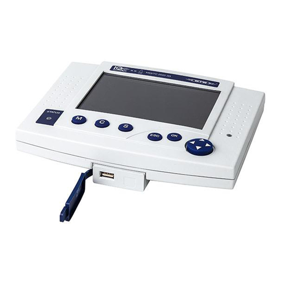
System 2020 XT Operation Operation MIQ/MC controller The MIQ/MC controller is the control unit of the IQ S ENSOR Terminal The terminal is the user interface of the IQ S ENSOR You can install the following terminal components: Terminal MIQ/TC 2020 XT, configured as a terminal ... -
Page 70: Overview Of The Operating Elements
Operation System 2020 XT 4.2.1 Overview of the operating elements This section gives basic information on the operation of the IQ S system via the MIC/TC 2020 XT (as terminal). ENSOR General key symbols are used for all operating steps in this operating manual. -
Page 71: Display
System 2020 XT Operation 4.2.2 Display The display contains the following information: Fig. 4-2 View of the display Name of the display Name of the terminal Date Time Lock safety setting: open (settings released) – System settings can be changed closed (settings locked) –... - Page 72 Operation System 2020 XT Measured value display The measured value display contains the following information for each IQ sensor/differential sensor: Fig. 4-3 Display - measured value display Consecutive numbering of the measured values Main measured value Unit and parameter of the main measured value Name of the sensor (to enter name: see section 5.4.1 Adjoining measured value with unit Special displays...
-
Page 73: Keys
System 2020 XT Operation 4.2.3 Keys Function <M> Display measured values <C> Start calibration of the IQ sensor selected in the measured value dis- play <S> Open the Einstellungen/Settings menu <ESC> Change to the higher menu levels or abort entries without storing them <OK>... -
Page 74: General Operating Principles
Operation System 2020 XT General operating principles The operation of the IQ S is standardized and user-friendly. ENSOR Select an item with the arrow keys <> – Highlight individual elements in menus, lists and tables, e.g. menu entries, list elements, columns or fields –... -
Page 75: Navigating In Menus, Lists And Tables
System 2020 XT Operation 4.3.1 Navigating in menus, lists and tables Using <S>, open the Einstellungen/Settings menu. Menus appear in the form of a list on the display, e.g. the Ein- stellungen/Settings menu shown here. Fig. 4-4 Settings Select a menu item (e.g. System settings) with <>. Move the highlighting (reverse video display, black back- ground) in the list of menu items with the arrow keys <>. -
Page 76: Entering Texts Or Numerals
Operation System 2020 XT 4.3.2 Entering texts or numerals You can assign names to IQ sensors, MIQ output modules, terminals and locations. Example: Entering a sensor name: Using <S>, open the Einstellungen/Settings menu. Select the Edit list of sensors menu item with <>. Confirm the Edit list of sensors menu item with <OK>. - Page 77 System 2020 XT Operation Fig. 4-6 Edit list of sensors Note The following letters, numerals and special characters can be entered: AaBb..Zz0..9µ%&/()+-=><!?_ °. Select a letter or numeral with <>. Confirm the letter with <OK>. The character appears behind the last letter. Fig.
- Page 78 Operation System 2020 XT Add a new character Select the character to be added with <> and con- firm with <OK>. Delete the last character Select the character with <> and confirm with <OK>. Adopt the name Select the character with <>...
-
Page 79: Display Of Current Measured Values
System 2020 XT Operation Display of current measured values Several options can be selected for displaying the measured values: Measured values (1 sensor) The measured value is shown numerically and as a bar graph on the Measured values (1 sensor) display (see section 4.4.1) ... -
Page 80: Displaying A Single Measured Value
Operation System 2020 XT 4.4.1 Displaying a single measured value The measured value is shown numerically and as a bar graph on the Measured values (1 sensor) display. Fig. 4-9 Values: all sensors -> Measured values (1 sensor) 4.4.2 Displaying four measured values Up to four measured values of IQ sensors or differential sensors are shown on the display at the same time. -
Page 81: Displaying Eight Measured Values
System 2020 XT Operation 4.4.3 Displaying eight measured values Up to eight measured values of IQ sensors or differential sensors are shown on the display at the same time. Fig. 4-11 Values: all sensors -> Measured values (8 sensors) ba64104e09 04/2012 4 - 13... - Page 82 Operation System 2020 XT 4.4.4 Displaying recorded measured values If the measured value recording has been activated for an IQ sensor (see section 5.10), the temporal course of the recorded measured val- ues can be displayed numerically and graphically. The following display options are possible: ...
-
Page 83: Displaying Recorded Measured Values
System 2020 XT Operation Displaying recorded Switch to the measured value display with <M>. measured values Select an IQ sensor with <>. Using <OK>, open the Display options menu. Select one of the display types with <> Monthly load of selected sensor ... -
Page 84: Transmitting Recorded Measuring Data To A Pc
Operation System 2020 XT 4.4.5 Transmitting recorded measuring data to a PC The recorded measured values can be transmitted to a PC with the aid of the MIQ/IF232 component. Details on data transmission are given in the MIQ/IF232 component operating manual. 4.4.6 Display of the measured values of a measurement location or of all IQ sensors in the system As soon as a terminal is docked onto a measurement location, the local... -
Page 85: Messages And Log Book
System 2020 XT Operation Messages and log book The IQ S continuously monitors the status of the entire sys- ENSOR tem. If the IQ S identifies system changes, a message ENSOR appears. New messages can be recognized by the flashing information symbol or error symbol on the display. - Page 86 Operation System 2020 XT Structure of the log book Fig. 4-14 Log book of entire system Message category (error or info symbol) Module that triggered the message. SYS system (controller) S01 IQ sensor (number 01) S?? IQ sensor (inactive, dataset deleted) D01 MIQ output module (number 01) D?? MIQ output module (inactive, dataset deleted) Message code...
- Page 87 System 2020 XT Operation Structure of the The message code consists of 6 characters and can contain numerals message code and letters, e.g.: II2121. Type number Type Component code Category II2 121 Pos. Information Explanation 1 - 3 Short message The short form of the message contains form the following information of the mes-...
-
Page 88: Viewing Detailed Message Texts
Operation System 2020 XT Note The detailed message text in the log book contains a precise descrip- tion of the message code and, if required, any further actions. The detailed message texts can also be found in the component oper- ating manuals of the individual components. -
Page 89: Acknowledge All Messages
System 2020 XT Operation Exit the message text with <ESC>. Note Acknowledgment of a new message text in the log book marks the message as read. When all errors or information messages are acknowledged, the symbols no longer flash. With the Acknowledge all messages function you can acknowledge all messages at the same time (see section 4.5.4). -
Page 90: Calibration Data
Operation System 2020 XT Calibration data Note Details on calibration are given in the operating manual for the IQ sensor. Each calibration of IQ sensors that are able to be calibrated causes an entry to be made in the log book. Log book entries contain the following information: ... -
Page 91: Calibration History
System 2020 XT Operation 4.6.2 Calibration history The calibration history contains the detailed calibration data of the last calibrations. Call up the measured value display with <M>. Using <>, highlight a sensor and confirm with <OK>. The Display options menu opens. Using <>, highlight the menu item, Calibration history of selected sensor, and confirm with <OK>. -
Page 92: Software Status
Operation System 2020 XT Software status The system gives information on the current versions of the software. 4.7.1 Software status of the controller and terminal Call up the measured value display with <M>. Using <S>, open the Einstellungen/Settings menu. Using <>, highlight the Service menu item and confirm with <OK>. -
Page 93: Software Status Of All Components
System 2020 XT Operation 4.7.2 Software status of all components Call up the measured value display with <M>. Using <S>, open the Einstellungen/Settings menu. Using <>, highlight the Service menu item and confirm with <OK>. The Service dialog window opens. Using <>, highlight the menu item, List of all compo- nents, and confirm with <OK>. -
Page 94: Status Info Of Sensors And Outputs
Operation System 2020 XT Status info of sensors and outputs The display of the instrument status provides a simple overview of the current modes of sensors (sensor info) and outputs in the IQ S ENSOR The status display can be reached in the Einstellungen/Settings/ Service/List of all components menu (see section 4.7). -
Page 95: General Course When Calibrating, Cleaning, Servicing Or Repairing An Iq Sensor
System 2020 XT Operation General course when calibrating, cleaning, servicing or repairing an IQ sensor When an IQ sensor is calibrated, cleaned, serviced or repaired, the maintenance condition for the relevant IQ sensor should always be switched on. In the maintenance condition ... -
Page 96: Maintenance Condition Of Iq Sensors
Operation System 2020 XT 4.9.1 Maintenance condition of IQ sensors The following diagram gives you an overview of when an IQ sensor is in the maintenance condition. Maintanance Sensor condition ON cleaning Measured value Measured value manually active Measured value display display display... -
Page 97: Switching On The Maintenance Condition
System 2020 XT Operation 4.9.2 Switching on the maintenance condition Switch on the maintenance condition manually when you want to clean, service or repair (remove and replace) an IQ sensor. Call up the measured value display with <M>. Select the sensor you want to switch on the maintenance condition for with <>. -
Page 98: Switching Off The Maintenance Condition
Operation System 2020 XT 4.9.3 Switching off the maintenance condition Call up the measured value display with <M>. Select the sensor you want to switch off the maintenance condition for with <>. The display of the sensor in the measured value display flashes. -
Page 99: Settings/Setup
(e.g. sensor, controller, terminal, output mod- ule) appear in the standard language, German. To activate the selected system language for this component, a software update of the compo- nent is required. Contact WTW. ba64104e09 04/2012 5 - 1... -
Page 100: Terminal Settings
Settings/setup System 2020 XT Terminal settings The available terminal settings depend on the terminal installed. The following terminals can be used: MIQ/TC 2020 XT, configured as a terminal MIQ/IF232 interface component with software terminal (see MIQ/ IF232 component operating manual) 5 - 2 ba64104e09 04/2012... -
Page 101: Releasing Or Locking Settings
System 2020 XT Settings/setup Releasing or locking settings Password protection can be switched on or off with the Unlock/lock set- tings function. The current setting is displayed in the safety field. The lock symbol is open or closed. Before any change of the release set- ting, a password query appears. -
Page 102: Editing The List Of Sensors
Settings/setup System 2020 XT Editing the list of sensors The Edit list of sensors display provides an overview of all IQ sensors, differential sensors and inactive datasets (see section 7.4.2). In the Edit list of sensors display, you can: assign sensor names (see section 5.4.1) ... -
Page 103: Changing The Display Position
System 2020 XT Settings/setup 5.4.2 Changing the display position The numbering of the sensors is generated by the system. The order of the sensors in the measured value display and in the Edit list of sensors overview can be individually determined. Using <S>, open the Einstellungen/Settings menu. -
Page 104: Erasing Inactive Sensor Datasets
Settings/setup System 2020 XT 5.4.3 Erasing inactive sensor datasets An inactive dataset for an IQ sensor arises if the controller receives no signals from a registered IQ sensor. The Error display appears on the measured value display instead of a measured value. Inactive datasets can be recognized by a question mark, e.g. -
Page 105: Setting Up Iq Sensors/Differential Sensors
System 2020 XT Settings/setup Setting up IQ sensors/differential sensors 5.5.1 Creating a differential sensor A differential sensor is a virtual sensor. It shows the differential value of two IQ sensors that measure the same parameter and have the same settings. This is used to display the difference, e.g. before and after a water treatment. -
Page 106: Erasing A Differential Sensor
Settings/setup System 2020 XT 5.5.2 Erasing a differential sensor If a differential sensor is no longer required, it can be erased from the list of sensors. Using <S>, open the Einstellungen/Settings menu. Using <> and <OK>, select and confirm the menu item, System settings ->... - Page 107 System 2020 XT Settings/setup Using <S>, open the Einstellungen/Settings menu. Using <> and <OK>, select and confirm the menu item, System settings -> Settings of sensors and diff. sensors. The Settings of sensors and diff. sensors display opens. Using <>, highlight the Measuring range column. Con- firm with <OK>.
-
Page 108: Editing The List Of Outputs
Settings/setup System 2020 XT Editing the list of outputs The Edit list of outputs display provides an overview of all outputs, links and inactive datasets (see section 7.4.3). In the Edit list of outputs display, you can: assign output names (see section 5.4.1) and ... - Page 109 System 2020 XT Settings/setup Fig. 5-10 Edit list of sensors ba64104e09 04/2012 5 - 11...
-
Page 110: Erasing An Inactive Dataset For An Miq Output Module
Settings/setup System 2020 XT 5.6.2 Erasing an inactive dataset for an MIQ output module An inactive dataset for an MIQ output module arises if the system receives no signals from a registered MIQ output module. Inactive datasets can be recognized by a question mark, e.g. "?01" in the Edit list of outputs overview. -
Page 111: Output Links/Settings
System 2020 XT Settings/setup 5.6.3 Output links/settings Note The procedure and possible settings for linking outputs with sensors are given in the operating manual of the respective output module. Settings for a measurement location Primarily, the settings for a measurement location simplify the calibra- tion of IQ sensors if several IQ sensors of the same type are operated on the system. - Page 112 Settings/setup System 2020 XT Entering the name of a The name of the measurement location is displayed in the line with the measuring location name of the display. 15 characters are available for the name of the measurement location. Press <> to select the name of the display, Select measured values of location and confirm with <OK>.
-
Page 113: Alarm Settings
System 2020 XT Settings/setup Alarm settings 5.8.1 General information Under this menu item you can specify reactions on certain alarm events. An alarm event is when a certain measured value (limiting value) of a sensor is exceeded or undercut. You can configure up to 20 alarm events. -
Page 114: Setting Up / Editing Alarms
Settings/setup System 2020 XT 5.8.2 Setting up / editing alarms Using <S>, open the Einstellungen/Settings menu. Using <> and <OK>, select and confirm the menu item, Alarm settings -> . The Alarm link overview dialog window opens. Alarms that have already been set up have entries in the Sen- sor column. - Page 115 System 2020 XT Settings/setup Fig. 5-14 Select Sensor for alarm link To set up a new alarm, select a sensor from the list with <> and confirm with <OK>. The Set alarm link display opens. Fig. 5-15 Set alarm link Edit the setting table.
- Page 116 Settings/setup System 2020 XT Alarm links setting table Menu item Selection/Values Explanations Main variable Measured variable Main variable designates the actual measured parameter of the sensor (e.g. Adjoining variable pH, oxygen, etc.). Adjoining variable designates an additional measured parameter (e.g. temperature).
-
Page 117: Alarm Output To Display
System 2020 XT Settings/setup 5.8.3 Alarm output to display When an alarm event occurs, a window with a text message appears. Fig. 5-16 Example of an alarm message on the display The alarm message contains the following information: Line 1: Alarm no. -
Page 118: Alarm Output As Relay Action
Settings/setup System 2020 XT 5.8.4 Alarm output as relay action The relay outputs of the IQ S can be configured so a relay ENSOR action is triggered when an alarm event occurs (Open or Close). For this the Alarm contact function must be set for the relay output in the Settings of outputs and links. -
Page 119: System Settings
System 2020 XT Settings/setup System settings System settings include: Change password (see section 5.9.1). Language (see section 5.1) Date/Time (see section 5.9.2) Loc. altitude (see section 5.9.3) 5.9.1 Changing the password A password protects the system settings against inadvertent changes. The password must always be entered in order to change the release of the settings. -
Page 120: Setting The Date And Time
Settings/setup System 2020 XT Note Forgotten the password? You can display the valid password on the screen (see section 11.1). 5.9.2 Setting the date and time The real time clock is used for the display of date and time in the mea- sured value display and in log book entries. -
Page 121: Site Altitude / Setting The Medium Air Pressure
System 2020 XT Settings/setup Note The clock in the MIQ/MC bridges periods of power failure of up to 24 hours. After a longer power failure, the clock starts precisely at the time of the failure. A message and an entry in the log book provide informa- tion on the power failure and the necessity for resetting the clock. - Page 122 Settings/setup System 2020 XT Press <> and <OK> to select and confirm Set altitude of location or Set air pressure. Press <> and <OK> to adjust and confirm the values for Loc. altitude or Air pressure. 5 - 24 ba64104e09 04/2012...
-
Page 123: Measured Value Logging
System 2020 XT Settings/setup 5.10 Measured value logging With the Measured value logging setting you can record and store mea- sured values of IQ sensors or differential sensors. You can display the stored measured values as a list or ... -
Page 124: Setting The Recording Interval (Dt) And Recording Duration (Dur.)
Settings/setup System 2020 XT 5.10.1 Setting the recording interval (dt) and recording duration (Dur.) Using <S>, open the Einstellungen/Settings menu. Using <> and <OK>, select and confirm the menu item, Measured value logging -> . The Measured value logging display opens. It contains a list of all sensors and inactive sensors. - Page 125 System 2020 XT Settings/setup Note The percentage of the memory blocks not yet allocated is shown on the display. If all memory blocks have already been allocated (Free stor- age: 0%), the number of memory blocks allocated to another IQ sensor may have to be reduced.
- Page 126 Settings/setup System 2020 XT 5 - 28 ba64104e09 04/2012...
-
Page 127: Maintenance And Cleaning
System 2020 XT Maintenance and cleaning Maintenance and cleaning Maintenance Maintenance activities Component Maintenance IQ sensors Depending on the type of sensor (see the component operating manual of the sensor) Other components No maintenance required Cleaning MIQ modules and Clean components mounted in the open of gross contamination as nec- control units essary. - Page 128 Maintenance and cleaning System 2020 XT 6 - 2 ba64104e09 04/2012...
-
Page 129: What To Do If
System 2020 XT What to do if ... What to do if ... Information on errors Log book The IQ S system performs a comprehensive cyclical self ENSOR test during operation. While doing so, the system identifies all states that deviate from normal operation and enters corresponding mes- sages in the log book (information or error message). -
Page 130: Measuring The Voltage
What to do if ... System 2020 XT 7.2.2 Measuring the voltage If an MIQ module shows an error condition (both LEDs off), this can be due to the following causes: The voltage supply has been interrupted The available voltage is not sufficient; the voltage is below the warn- ing range. - Page 131 System 2020 XT What to do if ... Note Safe voltage measurement is possible on the module contacts on the outside of MIQ/PS and relay output modules (see Fig. 7-1). Front: Tapping points for measuring the voltage ...+ U ...+ U SENSORNET connections on the terminal strip (example): ...+ U ...+ U...
-
Page 132: Tips For Clearing Errors In The Voltage Supply
What to do if ... System 2020 XT 7.2.3 Tips for clearing errors in the voltage supply Note Admissible values for the internal voltage supply (+U) are given in section 8.1. Supply voltage not Cause Remedy present or in the –... - Page 133 – IQ sensor is defective – Test IQ sensor at another mea- surement location. – If IQ sensor still does not func- tion, contact WTW. Other components – Component is defective – If possible, test component at another measurement location.
-
Page 134: Other Errors
What to do if ... System 2020 XT Other errors The system does no Cause Remedy longer react on entries – System error Reset the system: – Switch off the power supply and switch it on again after 10 s –... - Page 135 What to do if ... The selected system Cause Remedy language was not – A system language was selected – Contact WTW, activated for all that is not available in at least a software update is components one component (sensor, control- required for the respective ler, terminal, output module).
-
Page 136: Replacing System Components
What to do if ... System 2020 XT Replacing system components Note It is always possible to replace components and assign a substitute if the software state of the substitute component is as high or higher as the software version of the original component. 7.4.1 Replacing passive components Passive components include all components that the controller cannot recognize. - Page 137 System 2020 XT What to do if ... Note The maximum number of data sets (active and inactive datasets) for IQ sensors is limited to 20 in the IQ S system 2020 XT. ENSOR When this number is reached, no further IQ sensor can be installed. If necessary, an inactive dataset has to be erased to make an extension possible.
- Page 138 What to do if ... System 2020 XT Case 2: The type of sensor is identical Operator intervention is required with the type of sensor in an here. The connected IQ sensor inactive dataset (or several can: inactive datasets), but the serial –...
- Page 139 System 2020 XT What to do if ... Operating sequence in Connect a new IQ sensor. case 2 Switch to the measured value display with <M>. The compo- nent database is updated. The following display appears (example): Fig. 7-2 Add/replace sensor Select the required option with <>...
-
Page 140: Adding And Replacing Miq Output Modules
What to do if ... System 2020 XT Select the required inactive dataset with <> and con- firm with <OK>. The system switches to the measured value display. The IQ sensor takes over all settings of the inactive dataset. As soon as the IQ sensor is ready for operation, it delivers a measured value. - Page 141 System 2020 XT What to do if ... Note The maximum number of data sets (active and inactive datasets) for MIQ output modules is limited to 8 in the IQ S system ENSOR 2020 XT. When this number is reached, no further MIQ output module can be installed.
- Page 142 What to do if ... System 2020 XT Switch to the measured value display with <M>. The compo- nent database is updated. The following display appears (example): Fig. 7-4 Add/replace output module Select the required option with <> and confirm with <OK>.
- Page 143 System 2020 XT What to do if ... Select the required inactive dataset with <> and con- firm with <OK>. The system switches to the measured value display. The MIQ output module takes over all settings of the inactive dataset. ba64104e09 04/2012 7 - 15...
-
Page 144: Perform A System Reset
What to do if ... System 2020 XT Perform a system reset Open the MIQ/MC module. Press the Reset button. The IQ S is restarted. ENSOR Reset button Fig. 7-6 Reset button Close the MIQ/MC module. 7 - 16 ba64104e09 04/2012... -
Page 145: Technical Data
System 2020 XT Technical data Technical data General system data Test marks cETLus, CE Ambient conditions Temperature Operation - 20 °C ... + 55 °C (- 4 ... 131 °F) Storage - 25 °C ... + 65 °C (- 13 ... 149 °F) Relative humidity ≤... - Page 146 Technical data System 2020 XT Warning A circuit (except for the power supply connections), that is con- nected to an IQ S component, must not feed any voltag- ENSOR es or currents that are not allowed. It has to be made sure that the circuit at any time meets all requirements of a Limited circuit or Limited Power as well as of SELV (Safety Extra Low Voltage).
- Page 147 System 2020 XT Technical data Note Instructions of how to measure the actual supply voltage on individual IQ S components are given in this operating manual in sec- ENSOR tion 7.2 D IAGNOSING FAULTS IN THE VOLTAGE SUPPLY Instrument safety Applicable norms –...
-
Page 148: General Data Of Miq Modules
Technical data System 2020 XT General data of MIQ modules Note Technical data on special MIQ modules are given in the respective operating manuals. Dimensions 144,0 52,2 Front view: Side view: 115,0 11,0 70,0 16,5 Rear view: Stack mounting: Fig. 8-2 Dimension drawing of MIQ module (dimensions in mm) 8 - 4 ba64104e09... - Page 149 System 2020 XT Technical data Mechanical construc- Maximum number of 3 plus terminal component tion MIQ modules in a mod- ule stack Enclosure material Polycarbonate with 20 % glass fiber Weight Approx. 0.5 kg Type of protection – IP 66 –...
-
Page 150: Miq/Mc Controller
Technical data System 2020 XT MIQ/MC controller Electrical data Supply voltage Max. 24 VDC via the IQ S (for ENSOR details, see section 8.1 G ENERAL SYSTEM DATA Power consumption 1.5 W Power consumption of MIQ/MC with "PR" or "MOD" option Air pressure Measuring range (MIQ/ 500 mbar ... - Page 151 System 2020 XT Technical data Panel mounting Panel mounting Space required for screwdriver Fig. 8-4 Space required for panel mounting (dimensions in mm) ba64104e09 04/2012 8 - 7...
- Page 152 Technical data System 2020 XT 8 - 8 ba64104e09 04/2012...
-
Page 153: Accessories And Options
Kit for mounting of MIQ modules on a THS/IQ 480 050 35 mm top hat rail in accordance with EN 50022 Note Other accessories for the IQ S are given in the WTW cata- ENSOR log or on the Internet. ba64104e09 04/2012 9 - 1... - Page 154 Accessories and options System 2020 XT 9 - 2 ba64104e09 04/2012...
-
Page 155: Indexes
System 2020 XT Indexes Indexes On the following pages, you will find the following indexes: Index of all displays (see section 10.1) Explanation of the message codes (see section 10.2) ba64104e09 04/2012 10 - 1... -
Page 156: Index Of All Displays
Indexes System 2020 XT 10.1 Index of all displays This index contains a selection of displays showing important indications or settings. Add/replace output module....................7-14 Add/replace sensor......................7-11 Alarm settings -> Alarm link overview................5-16 Assign output module as a substitute ................7-14 Assign sensor as a substitute .................... -
Page 157: Explanation Of The Message Codes
* Check installation and cable lengths, Follow installation instructions * Set SN terminator switch acc. to operating manual * Check environmental effects * Component defective, contact WTW EI9121 Power failure occurred * Check date and time and, if necessary, adjust them... -
Page 158: Info Messages
Message code Message text EA8121 Automatic air pressure measurement of MIQ/MC defective An air pressure value of 1013 mbar is used for air pressure compen- sation * Contact WTW 10.2.2 Info messages Message code Message text II1121 Language not available,... -
Page 159: Index
IQ S System 2020 XT Lists ENSOR 10.3 Index Output module ......5-12, 7-12 Sensors ........5-6, 7-8 Air pressure ..........5-23 Information ..........4-17 Ambient conditions ......3-1, 8-1 Initialization ..........3-38 Authorized use .......... 2-2 Keys ............4-5 Basic components ........ - Page 160 Lists IQ S System 2020 XT ENSOR sensor ..........5-4 Terminal ..........5-2 Time ...........5-22 Signal amplifier module ......3-9 Single sensors ...........1-7 Obligations of the operator ......2-3 Site altitude ..........5-23 Operating elements ........4-2 SN terminator switch ......3-35, 3-41 Operating principles ........4-6 SNCIQ cable ........3-21, 3-22 Operational safety ........2-2 SNCIQ/UG earth cable ....3-21, 3-22 Output channels ........1-8...
-
Page 161: Appendix (Store Separately If Required)
System 2020 XT Appendix (store separately if required) Appendix (store separately if required) 11.1 Forgotten the password? Proceed as follows to show the currently valid password on the display: Using <S>, open the Einstellungen/Settings menu. Using and <OK>, select and confirm the menu item, Sys- tem settings ->... -
Page 162: Default Password
Appendix (store separately if required) System 2020 XT 11.2 Default password When the Terminal/Controller is delivered, the password is set to 1000. 11 - 2 ba64104e09 04/2012... - Page 164 Wissenschaftlich-Technische Werkstätten GmbH Dr.-Karl-Slevogt-Straße 1 D-82362 Weilheim Germany Tel: +49 (0) 881 183-0 +49 (0) 881 183-100 Fax: +49 (0) 881 183-420 E-Mail: Info@WTW.com Internet: http://www.WTW.com...
Need help?
Do you have a question about the IQ SENSOR NET System 2020 XT and is the answer not in the manual?
Questions and answers