Sign In
Upload
Manuals
Brands
wtw Manuals
Touch terminals
IQ SENSOR NET System 2020 XT
User Manuals: wtw IQ SENSOR NET System 2020 XT Control
Manuals and User Guides for wtw IQ SENSOR NET System 2020 XT Control. We have
2
wtw IQ SENSOR NET System 2020 XT Control manuals available for free PDF download: Operating Manual
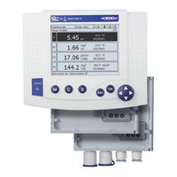
WTW IQ SENSOR NET System 2020 XT Operating Manual (216 pages)
Modular multi-parameter measuring system
Brand:
WTW
| Category:
Measuring Instruments
| Size: 2 MB
Table of Contents
Table of Contents
3
1 Overview
9
How to Use this System Operating Manual
9
The IQ SENSOR NET System2020 XT
10
Structure of the System
10
Functions in the IQ SENSOR NET
11
Possible Ways to Communicate with the IQ SENSOR NET
12
Components of the System 2020 XT
14
MIQ Modules
17
MIQ/MC2 Controller
19
Terminals
20
Behavior of the IQ SENSOR NET in Case of Power Failure
20
Behavior of the IQ SENSOR NET if a Components Fails
21
Availability of the System
22
Ensor Net
22
2 Safety
25
Safety Information
25
Safety Information in the Operating Manual
25
Safety Signs on the Product
25
Further Documents Providing Safety Information
25
Safe Operation
26
Authorized Use
26
Requirements for Safe Operation
26
Unauthorized Use
26
User Qualification
26
3 Installation
29
Scopes of Delivery
29
Requirements of the Measurement Location
29
Basics of the Installation
30
System Planning
30
Basic Requirements for Optimum Installation
31
General Information
31
Drawing up the Power Rating
31
Effect of the Cable Length
34
Optimum Installation of MIQ Power Supply Modules
38
Installation Guidelines for Lightning Protection
38
Connecting System Components
41
General Information
41
Stacked Mounting of MIQ Modules
42
Distributed Mounting of MIQ Modules
49
Connecting IQ Sensors
53
Installation of the MIQ Modules at the Installation Location
55
General Information
55
Mounting on a Mounting Stand with the SSH/IQ Sun Shield
56
Mounting under the SD/K 170 Sun Shield
58
Panel Mounting
60
Top hat Rail Mounting
62
Electrical Connections: General Instructions
63
Connecting the Voltage Supply
64
Ethernet Connection in Case of Outdoor Installation
65
Commissioning
67
Topology and Terminator Switch
67
Start Checklist and System Start
69
Checking the Voltage Supply
71
System Extension and Modification
73
General Information
73
4 Operation
75
MIQ/MC2 Controller
75
Terminal
75
Overview of the Operating Elements
76
Display
77
Keys
80
Arrow Keys
80
General Operating Principles
81
Navigating in Menus, Lists and Tables
82
Entering Texts or Numerals
83
Access to the IQ SENSOR NET with Active Access Control
86
Simple Access Control
87
Extended Access Control
88
Extended Access Control with Instrument Block
89
Display of Current Measured Values
90
Measured Values (4 Sensors)
90
Measured Values (8 Sensors)
90
Displaying a Single Measured Value
91
Displaying Four Measured Values
91
Displaying Eight Measured Values
92
Displaying Recorded Measured Values
94
Display of the Measured Values of a Measurement Location or of All IQ Sensors in the System
95
Transmitting Recorded Measuring Data to a PC
95
Messages and Log Book
96
Message Types
96
Log Book
96
Viewing Detailed Message Texts
99
Acknowledge All Messages
100
Calibration Data
101
Calibration Entries in the Log Book
101
Calibration History
102
Status Info of Sensors and Outputs
103
General Course When Calibrating, Cleaning, Servicing or Repairing an IQ Sensor
104
Maintenance Condition of IQ Sensors
105
Switching on the Maintenance Condition
106
Switching off the Maintenance Condition
107
USB Interface
108
Transmitting Recorded Measurement Data to a PC
110
Ensor Net
110
Saving the System Configuration Manually
110
Software-Update for IQ SENSOR NET
111
Info on Software Versions
112
5 Settings/Setup
113
Selecting the Language
113
Language
113
Terminal Settings
114
Releasing or Locking Settings
114
Editing the List of Sensors
115
Entering / Editing a Name for an IQ Sensor
115
Changing the Display Position
116
Erasing Inactive Sensor Datasets
118
Setting up IQ Sensors/Differential Sensors
119
Creating a Differential Sensor
119
Erasing a Differential Sensor
120
Adjusting the Settings for Sensors/Differential Sensors
120
Editing the List of Outputs
121
Entering / Editing the Name of an Output
122
Edit List of Outputs -> Enter a Name
122
Erasing an Inactive Dataset for an MIQ Output Module
124
Erase Output Module
124
Output Links/Settings
125
Settings for a Measurement Location
125
140 - Settings of Sensors and Diff. Sensors -> Link with
126
Location Display
126
Alarm Settings
127
General Information
127
Setting up / Editing Alarms
128
Alarm Output to Display
131
Alarm Output as Relay Action
132
System Settings
133
Changing the Password
133
Setting the Date and Time
134
Date/Time
134
160 - Measured Value Logging
126
180 - System Settings -> Change Password
134
Measured Value Logging
135
6 Network Connection
139
Configuring the Ethernet Network
139
Communication in a Local Network (LAN)
141
Communication on the Internet
142
Ensor Net
142
General Information
144
Communication with the Web Server of the MIQ/MC2
144
Communication Via a PC
146
Installation of the IQ Software Pack CONNECT
147
Troubleshooting
148
Technical Network Terms
150
7 Modbus Connection (Option)
153
Modbus Checklist
153
Connecting the Modbus Cable
154
Setting the Modbus Interface Parameters
156
Transmitted Sensor Data
157
Overview
157
Sensor Administration under Modbus
158
Sensor Data Block
159
Data Formats
161
Modbus Query
163
Modbus Error Elimination
166
8 PROFIBUS Connection (Option)
167
PROFIBUS Checklist
167
Connecting the PROFIBUS Cable
169
Setting the PROFIBUS Address
171
GSD File
171
Transmitted Sensor Data
172
Overview
172
Sensor Administration under PROFIBUS
173
Output Data
174
Input Data
175
Data Formats
176
PROFIBUS Error Elimination
177
9 Maintenance and Cleaning
179
Maintenance
179
Cleaning
179
10 What to Do if
181
Information on Errors
181
Diagnosing Faults in the Voltage Supply
181
Options for Checking the Voltage
181
Measuring the Voltage
182
Tips for Clearing Errors in the Voltage Supply
184
Other Errors
186
Replacing System Components
187
Replacing Passive Components
187
Adding and Replacing IQ Sensors
188
Adding and Replacing MIQ Output Modules
191
393 - List of All Components with Sensor Info
193
Assign Output Module as a Substitute
193
410 - Add/Replace Output Module
193
11 Technical Data
195
General System Data
195
General Data of MIQ Modules
198
Miq/Mc2
200
Space Required by Mounted Components
202
12 Accessories and Options
203
13 Indexes
205
Index of All Displays
205
Edit List of Sensors
206
Removing the Safety Bracket
206
Explanation of the Message Codes
207
Error Messages
207
Info Messages
208
Index
209
14 Appendix (Store Separately if Required)
213
Forgotten the Password
213
Default Password
214
Advertisement
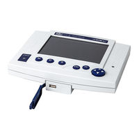
wtw IQ SENSOR NET System 2020 XT Operating Manual (164 pages)
Brand:
wtw
| Category:
Touch terminals
| Size: 2 MB
Table of Contents
Table of Contents
3
Iq Sensor Net
7
The IQ SENSOR NET System2020 XT
8
Structure of the System
8
Functions in the IQ SENSOR NET
10
Possible Ways to Communicate with the IQ SENSOR NET
11
Components of the System 2020 XT
13
MIQ Modules
16
MIQ/MC Controller
18
Behavior of the IQ SENSOR NET in Case of Power Failure
19
Behavior of the IQ SENSOR NET if a Components Fails
20
Availability of the System
21
1 Overview
7
How to Use this System Operating Manual
7
2 Safety Instructions
23
User Qualification
23
Authorized Use
24
General Safety Instructions
24
3 Installation
27
Scopes of Delivery
27
MIQ Modules
27
Controller
27
Requirements of the Measurement Location
27
Basic Principles of Installation
28
System Planning
28
Basic Requirements for Optimum Installation
29
General Information
29
Drawing up the Power Rating
29
Effect of the Cable Length
32
Optimum Installation of MIQ Power Supply Modules
36
Installation Guidelines for Lightning Protection
36
Connecting System Components
39
General Information
39
Stacked Mounting of MIQ Modules
40
Distributed Mounting of MIQ Modules
47
Connecting IQ Sensors
51
Installation of the MIQ Modules at the Installation Location
53
General Information
53
Mounting on a Mounting Stand with the SSH/IQ Sun Shield
54
Mounting under the SD/K 170 Sun Shield
56
Panel Mounting
58
Top hat Rail Mounting
60
Connecting the Voltage Supply
61
Commissioning
61
Topology and Terminator Switch
61
Start Checklist and System Start
63
Checking the Voltage Supply
65
System Extension and Modification
67
General Information
67
4 Operation
69
MIQ/MC Controller
69
Terminal
69
Overview of the Operating Elements
70
Display
71
Keys
73
Rotary Switch
73
General Operating Principles
74
Navigating in Menus, Lists and Tables
75
Entering Texts or Numerals
76
Display of Current Measured Values
79
Displaying a Single Measured Value
80
Displaying Four Measured Values
80
Displaying Eight Measured Values
81
Displaying Recorded Measured Values
83
Transmitting Recorded Measuring Data to a PC
84
Display of the Measured Values of a Measurement Location or of All IQ Sensors in the System
84
Messages and Log Book
85
Message Types
85
Log Book
85
Viewing Detailed Message Texts
88
Acknowledge All Messages
89
Calibration Data
90
Calibration Entries in the Log Book
90
Calibration History
91
Software Status
92
Software Status of the Controller and Terminal
92
Software Status of All Components
93
Status Info of Sensors and Outputs
94
General Course When Calibrating, Cleaning, Servicing or Repairing an IQ Sensor
95
Maintenance Condition of IQ Sensors
96
Switching on the Maintenance Condition
97
Switching off the Maintenance Condition
98
5 Settings/Setup
99
Selecting the Language
99
Terminal Settings
100
Releasing or Locking Settings
101
Editing the List of Sensors
102
Entering / Editing a Name for an IQ Sensor
102
Changing the Display Position
103
Erasing Inactive Sensor Datasets
104
Setting up IQ Sensors/Differential Sensors
105
Creating a Differential Sensor
105
Erasing a Differential Sensor
106
Adjusting the Settings for Sensors/Differential Sensors
106
Editing the List of Outputs
108
Entering / Editing the Name of an Output
108
Erasing an Inactive Dataset for an MIQ Output Module
110
Output Links/Settings
111
Settings for a Measurement Location
111
Alarm Settings
113
General Information
113
Setting up / Editing Alarms
114
Alarm Output to Display
117
Alarm Output as Relay Action
118
Alarm Message as an SMS
118
System Settings
119
Changing the Password
119
Setting the Date and Time
120
Site Altitude / Setting the Medium Air Pressure
121
Measured Value Logging
123
Setting the Recording Interval (Dt) and Recording Duration (Dur.)
124
6 Maintenance and Cleaning
127
Maintenance
127
Cleaning
127
7 What to Do if
129
Information on Errors
129
Diagnosing Faults in the Voltage Supply
129
Options for Checking the Voltage
129
Measuring the Voltage
130
Tips for Clearing Errors in the Voltage Supply
132
Other Errors
134
Replacing System Components
136
Replacing Passive Components
136
Adding and Replacing IQ Sensors
136
Adding and Replacing MIQ Output Modules
140
Perform a System Reset
144
8 Technical Data
145
General System Data
145
General Data of MIQ Modules
148
MIQ/MC Controller
150
Space Required by Mounted Components
150
9 Accessories and Options
153
10 Indexes
155
Index of All Displays
156
Explanation of the Message Codes
157
Error Messages
157
Info Messages
158
Index
159
11 Appendix (Store Separately if Required)
161
Forgotten the Password
161
Default Password
162
Advertisement
Related Products
WTW System 2020 3G
wtw 201 425
wtw Series 298
wtw PROTOC 200
wtw 230 VAC
wtw 208210
wtw 208211
wtw 208212
wtw 2F30-100
wtw inoLab 740
wtw Categories
Measuring Instruments
Accessories
Laboratory Equipment
Control Unit
Touch terminals
More wtw Manuals
Login
Sign In
OR
Sign in with Facebook
Sign in with Google
Upload manual
Upload from disk
Upload from URL