Sign In
Upload
Manuals
Brands
Omron Manuals
Other
V700-HMD11-1
Omron V700-HMD11-1 Manuals
Manuals and User Guides for Omron V700-HMD11-1. We have
2
Omron V700-HMD11-1 manuals available for free PDF download: User Manual
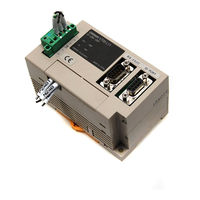
Omron V700-HMD11-1 User Manual (80 pages)
FOR SEMI STANDARD-COMPATIBLE CIDRW SYSTEM
Brand:
Omron
| Category:
Other
| Size: 1.44 MB
Table of Contents
Meanings of Signal Words
4
Meanings of Alert Symbols
4
Alert Statements in this Manual
4
Introduction
4
Precautions for Correct Use
5
Limitations about Model V700-HMD13
6
Table of Contents
7
Contents
7
Section 1 System Configuration and Features
9
System Configuration
10
Features
11
Section 2 Unit Specifications
13
CIDRW Controller: Model V700-L21
14
Names and Functions of Various Components/Specifications
14
Interface Specifications
17
Dimensional Drawing and Mounting Method
19
Names and Functions of Various Components/Specifications
20
Link Unit: Model V700-L11
20
Interface Specifications
23
Dimensional Drawing and Mounting Method
26
IDR/W Head: Model V700-HMD13
27
Names and Functions of Various Components/Specifications
27
Interface Specifications (same as with Model V700-HMD11-1)
28
Dimensional Drawing and Mounting Method
29
Communication Performance (Information Only)
31
IDR/W Head: Model V700-HMD11-1
32
Names and Functions of Various Components/Specifications
32
Interface Specifications (same as with Model V700-HMD13 )
33
Dimensional Drawing and Mounting Method
34
Communication Performance (Information Only)
35
ID Tag: Model V700-D23P41
36
Dimensional Drawing and Specifications
36
Memory Map
37
Section 3 System Connections
39
Connection Work and Startup
40
System Configuration Example
41
Section 4 SECS Protocol Specifications
43
Operation Model
44
Protocol Specifications
45
Support Attributes
47
Message Specifications
49
Operating Conditions
62
Section 5 Setup Mode
63
Accessing Setup Mode
64
How to Set up Parameters
65
Section 6 Reference
69
Processing Time (Information Only)
70
Performance Data Based on Operating Conditions (Information Only)
71
Effect of Nearby Metal Object Onto IDRW Head
71
Spacing for Installing IDRW Heads
72
Effect of Inclination of ID Tag
73
Section 7 Troubleshooting
75
No Acknowledge Message (Acknowledge Message Not yet Received)
76
Acknowledge Message Received (Other than SSACK="NO")
77
Revision History
79
Advertisement
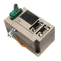
Omron V700-HMD11-1 User Manual (63 pages)
FOR RFID SYSTEM FOR SEMI CONDUCTOR DEVICE FABRICATION LINE
Brand:
Omron
| Category:
Other
| Size: 1.1 MB
Table of Contents
Meanings of Signal Words
4
Meanings of Alert Symbols
4
Alert Statements in this Manual
4
Introduction
4
Precautions for Correct Use
5
Limitations about Model V700-HMD13
6
Table of Contents
7
Contents
7
Section 1 System Features and Configuration
9
System Features
10
System Configuration
11
Section 2 Unit Specifications
13
IDR/W Head: Model V700-HMD13
14
Names and Functions of Various Components/Specifications
14
Names and Functions of Various Components/ Specifications
14
Interface Specifications (same as with Model V700-HMD11-1)
15
Dimensional Drawing and Mounting Method
17
Communication Performance (Information Only)
19
IDR/W Head: Model V700-HMD11-1
20
Names and Functions of Various Components/Specifications
20
Names and Functions of Various Components/ Specifications
20
Interface Specifications (same as with Model V700-HMD13 )
21
Specifications
21
Dimensional Drawing and Mounting Method
23
Communication Performance (Information Only)
24
ID Link Unit: Model V700-L11
25
Names and Functions of Various Components/Specifications
25
Interface Specifications
28
Dimensional Drawing and Mounting Method
32
ID Tag: Model V700-D23P41-1
33
Section 3 System Configuration Examples
35
Configuration Based on Upstream Controller and RS-232C
36
Configuration Based on Upstream Controller and RS-485
37
Section 4 Data Read/Write with ID Tag
39
Operating Principle
40
Command/Response Frame Structure
41
Response Code List
43
Command Types and Response <Applicable to OMRON Original 1:1 Protocol
44
Read
44
Write
45
Same Write
46
Byte Write
47
Test
48
Section 5 Data Transaction Time (Information Only)
49
Data Transaction Time
50
TAT (Turn Around Time)
51
Section 6 Performance Data Based on Operating Conditions (Information Only)
53
Effect of Nearby Metal Object Onto IDRW Head
54
Spacing for Installing IDRW Heads
55
Effect of Inclination of ID Tag
56
Section 7 Troubleshooting
57
IDRW Head Is Directly Connected to Upstream Controller
58
No Response (Response Not yet Received), Or, Occurrence of Illegal Characters
58
Response Is Available (Response Code Is Other than "00")
58
Configuration Using Link Unit
59
No Response (Response Not yet Received), or Occurrence of Illegal Characters
59
Response Is Available (Response Code Is Other than "00")
60
Memory Assignment with SEMI E99-Conforming System (with Model V700-L21)
61
Revision History
62
Advertisement
Related Products
Omron V700-HMD13 series
Omron V700-HMD13A
Omron V700-HMD11
Omron V700-H01
Omron V700-H02
Omron V700-D23P41
Omron V700-L21
Omron V700-D23P41-1
Omron V700-D13P21
Omron V700-CD1D
Omron Categories
Blood Pressure Monitor
Controller
Accessories
Switch
Inverter
More Omron Manuals
Login
Sign In
OR
Sign in with Facebook
Sign in with Google
Upload manual
Upload from disk
Upload from URL