Advertisement
Quick Links
Installation Instructions for JDB, JD, HJD, JDC, JW HJW,
JWC Circuit Breakers and Molded Case Switches
!
DO NOT ATTEMPT TO INSTALL OR PERFORM
MAINTENANCE ON EQUIPMENT WHILE IT IS ENER-
GIZED. DEATH, SEVERE PERSONAL INJURY, OR
SUBSTANTIAL PROPERTY DAMAGE CAN RESULT
FROM CONTACT WITH ENERGIZED EQUIPMENT.
ALWAYS VERIFY THAT NO VOLTAGE IS PRESENT
BEFORE PROCEEDING WITH THE TASK, AND
ALWAYS FOLLOW GENERALLY ACCEPTED SAFE-
TY PROCEDURES.
CUTLER-HAMMER IS NOT LIABLE FOR THE MISAP-
PLICATION OR MISINSTALLATION OF ITS PROD-
UCTS.
The user is cautioned to observe all recommendations,
warnings, and cautions relating to the safety of person-
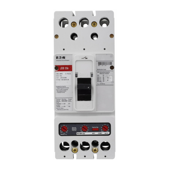
Figure 1-1 J-Frame Model D Series C Circuit Breaker
with JT Trip Unit Installed
WARNING
nel and equipment as well as all general and local
health and safety laws, codes, and procedures.
The recommendations and information contained herein
are based on Cutler-Hammer experience and judgment,
but should not be considered to be all-inclusive or cov-
ering every application or circumstance which may
arise. If any questions arise, contact Cutler-Hammer for
further information or instructions.
1. INTRODUCTION
General Information
The J-frame Series C circuit breaker (Figure 1-1) types
JD, JDB, HJD, and JDC are 600 Vac maximum rated
devices with inter changeable thermal-magnetic trip
units rated 250A maximum continuous current. Circuit
breaker types JW, HJW, and JWC are 660 Vac maxi-
mum rated devices using interchangeable adjustable
thermal/adjustable magnetic or electronic trip units rated
up to 250A continuous current. The type JDB noninter-
changeable trip circuit breaker is rated 600 Vac maxi-
mum with a maximum continuous current rating of
250A. Refer to Table 1-1 for all available trip unit rat-
Table 1-1 Available Trip Unit Ratings
Circuit Breaker
Trip Unit Types
Types
Thermal-Magnetic Amperes I
Fixed
Thermal
JDB
70
JD
90
HJD
100
JDC
JW
125
HJW
150
JWC
175
200
225
250
Not UL listed.
1
For adjustable thermal trip units, the magnetic setting is a multiple
2
of the maximum thermal setting.
I.L. 29C103G
n
Adjustable
Adjustable
Thermal
Magnetic
1
of I
2
n
5 to 10
100-125
125-160
160-200
200-250
Advertisement

Related Manuals for Eaton JDB


Summary of Contents for Eaton JDB
- Page 1 CUTLER-HAMMER IS NOT LIABLE FOR THE MISAP- The J-frame Series C circuit breaker (Figure 1-1) types PLICATION OR MISINSTALLATION OF ITS PROD- JD, JDB, HJD, and JDC are 600 Vac maximum rated UCTS. devices with inter changeable thermal-magnetic trip units rated 250A maximum continuous current. Circuit...
-
Page 2: Installation
To install the circuit breaker, perform the following steps. NOTICE JDB circuit breakers are factory sealed for reverse feed applications under UL489. UL requires that internal accessories be installed at the factory in this type of circuit breaker. - Page 3 I.L. 29C103G Page 3 before installation of the conductors, the terminal mount- ing screw can be checked or retightened through the TA250KB Terminal terminal when the conductor screw is removed. When using terminal (Catalog No. T250KB), secure the termi- Terminal Collar nal to the circuit breaker using screw and nut.
- Page 4 I.L. 29C103G Page 4 2, 3 Pole Breakers 4-Pole Breakers 1.562 (39.67) 2.750 .344R 1.375 .781 (69.85) (8.74) (34.37) 1.375 (19.84) .688 (34.37) (14.47) 2.922 (74.22) .250-20 3.938 (M6-1.0) (100.02) 4.078 Circuit Breaker Handle (103.58) (6 Holes) .781 Circuit Breaker Handle .875 7.250 (22.22)
- Page 5 I.L. 29C103G Page 5 Handle Position Indicator Color Red – ON White – TRIP Adjustment Green – OFF (Reset) Buttons TRIP (Reset) Off/ Figure 3-2 Trip Unit Magnetic Trip Adjustment Buttons International Symbols Table 2-1 Terminal Types Thermal-Magnetic Push-To-Trip Trip Unit Adjustment Button Terminal Terminal Screw...
- Page 6 I.L. 29C103G Page 6 4-5. Check terminals and connectors for looseness or CAUTION signs of overheating. Overheating will show as discol- oration, melting, or blistering of conductor insulation, or as pitting or melting of conductor surfaces due to arcing. MAKE SURE THAT CLEANING AGENTS OR SOL- If there is no evidence of overheating or looseness, do VENTS USED TO CLEAN THE CIRCUIT BREAKER not disturb or tighten the connections.
- Page 7 I.L. 29C103G Page 7 Effective 1/10...
- Page 8 I.L. 29C103G Page 8 Eaton Electrical, Inc. 1000 Cherrington parkway Moon Township, PA 15108-4312 Tel: 1-800-525-2000 www.EatonElectrical.com ©2010 Eaton corporation All Rights Reserved Printed USA/TQC Style 6632C43H08 Printed in U.S.A. /TQC E ective January 2010...