Page 1
Effective November 2010 Instruction Booklet IB 33-790-1J Supersedes IB 33-790-1I Dated 10/98 Instructions for Low Voltage Power Circuit Breakers Types DS and DSL...
Page 2
Instruction Booklet IB 33-790-1J Instructions for Low Voltage Power Circuit Breakers Types DS and DSL Effective November 2010 This Page Left Intentionally Blank. EaToN CorPoraTIoN www.eaton.com...
Page 5
Sensor and Limiter Ratings............EaToN CorPoraTIoN www.eaton.com...
Page 6
Type DS-206 Pole Unit Assembly - Rear View ........EaToN CorPoraTIoN www.eaton.com...
Page 7
Contacts and their Adjustment, DS-206 Breaker ........Contacts and their Adjustment, DS-416/420 Breaker ......EaToN CorPoraTIoN www.eaton.com...
Page 8
Lubrication Points on Right Side of Mechanism ........EaToN CorPoraTIoN www.eaton.com...
Page 9
This instruction book is expressly intended to cover the installation, operation and maintenance of Low Voltage Power Circuit Breakers, Types DS and DSL. For application information, consult your nearest Eaton sales office, see Eaton Descriptive Bulletin 32-850, or appropriate ANSI Standards.
Page 10
CAUTION The circuit breakers described in this book were designed and tested to operate within their nameplate ratings. Operation outside of these ratings may cause the equipment to fail, resulting in bodily injury and property damage. viii EaToN CorPoraTIoN www.eaton.com...
These instructions cover the description, operation and DS and DSL Breakers are available for application at volt- maintenance of Eaton Type DS and Type DSL ages from 208 to 600 Vac; with continuous currents of 50 Low Voltage AC Power Circuit Breakers and Type DS to 4000 amps;...
Any questions about chutes), barriers, and an Amptector solid-state trip unit. the circuit breakers may be referred to the nearest Eaton DSL breakers have added current limiters to extend their Sales Office. When making inquiries about type DS interrupting range to 200,000 amps.
2. DS-206S uses the DS-416 arc chute. 1600 amperes. 3. DS-206S main disconnects have 50% more fingers Compared to Type DS-416, DS-416S has higher inter- than the DS-206. rupting ratings, giving it improved operating flexibility (see Table 1). EaToN CorPoraTIoN www.eaton.com...
The fuse truck is key or while it is standing in any intermediate location between the TEST and the CONNECT positions or interlocked with the breaker to prevent withdrawing or the DISCONNECT position. insertion unless the breaker is open. EaToN CorPoraTIoN www.eaton.com...
13. Before operating breaker in test position, be sure that chains, etc., to avoid possible damage to parts or closing the breaker will not cause another electrically dropping the unit. Use breaker lifting adapter. interlocked breaker to inadvertently trip. EaToN CorPoraTIoN www.eaton.com...
Receiving and handling of this equipment is covered in 1.2 WEIGHTS: CIRCUIT BREAKERS AND FUSE Eaton Instruction Book 32-690 for Low-Voltage TRUCKS Metal-Enclosed Switchgear, Types DS and DSO. Table 3 gives the approximate weights of DS and DSL cir- If the circuit breakers are not shipped in the switchgear cuit breakers.
The hex shaft of the levering device will Shipped Inside Its Own Compartment. be exposed and ready to receive the levering crank handle (see Figure 3). Insert the crank and turn in a counter-clockwise direction and observe the action of EaToN CorPoraTIoN www.eaton.com...
Actual lifting may be with a crane, chain block or with the optional lifting mechanism which can be supplied for the switchgear. The breaker must be pulled completely to the end of the rails. EaToN CorPoraTIoN www.eaton.com...
6. The interlocks, which increase the safety of opera- The Amptector solid-state overcurrent tripping sys- tion. tem. 7. Drawout element position indicator. ® Digitrip RMS overcurrent tripping system (see Fig. 5b). Fig. 5a 
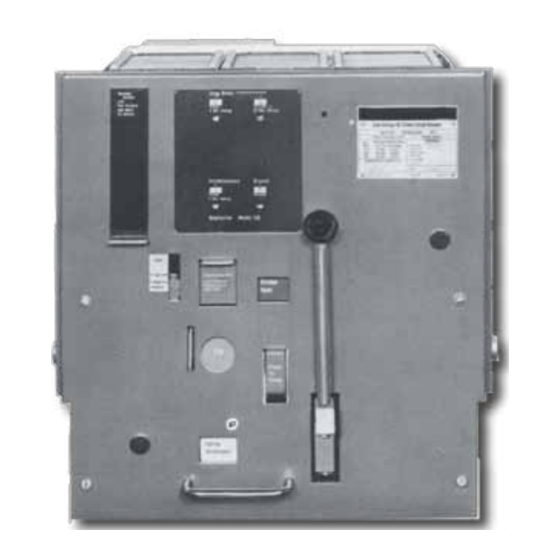
View Showing Controls on the Panel (Pre 1988). EaToN CorPoraTIoN www.eaton.com...
Effective November 2010 DIGITRIP RMS TRIP UNIT NAMEPLATE EMERGENCY CHARGING SHUTTER HANDLE OPEN-CLOSE DRAWOUT UNIT INDICATOR POSITION INDICATOR PADLOCK PLATE CLOSE BAR TRIP PLATE SPRING CHARGE INDICATOR Fig. 5b View Showing Controls on the Panel (Post 1988). EaToN CorPoraTIoN www.eaton.com...
Fig. 6a Left Side of Breaker with Levering Device Arm in Fig. 6b DS 416 Breaker with Front Panel Removed. REMOVE Position. Fig. 7 Right Side Showing Levering Device Arm in TEST Fig. 8 Rear View Showing Levering Device Arm in Position. CONNECT Position. EaToN CorPoraTIoN www.eaton.com...
This handle is placed on the levering device hand-push on the close bar. As optional equipment, the worm shaft, which is exposed by depressing the shutter. electrical spring release attachment normally supplied only on power-operated breakers can be supplied on manually operated breakers. EaToN CorPoraTIoN www.eaton.com...
4.2 CHARGE THE CLOSING SPRINGS reached. Now rotate the crank clockwise to simulate The closing springs must be charged before the breaker levering the breaker inward toward the CONNECT POSI- can be closed. To manually charge the closing springs, EaToN CorPoraTIoN www.eaton.com...
Note that the breaker position indicator now shows “Breaker-open”, 4.3 CLOSE THE BREAKER against a green background. The breaker can be closed only when the following condi- tions are met: EaToN CorPoraTIoN www.eaton.com...
Lever the breaker into the connected position as previ- Note however, that before the stop is reached, an ously described, and latch the compartment door. increase in load on the crank will be felt after the breaker EaToN CorPoraTIoN www.eaton.com...
DS and DSL breakers: Power-Operated; and Manually Operated. Fig. 11 Front View of Mechanism (Power-Operated Spring Charge). Fig. 10 Front View of Mechanism (Manual Spring Charge Fig. 12 Rear of Power-Operated Mechanism. Except for DS-632/840). EaToN CorPoraTIoN www.eaton.com...
Closing springs charged (16a); and At the instant that the springs snap over dead center, the Closing springs discharged (16b). lobes of the drive plates raise the pawl lifters (27), and EaToN CorPoraTIoN www.eaton.com...
The standard basic schematic and connection diagrams are shown in Figure 19a and b. Device Y is the anti-pump relay. Fig. 14 Arrangement of the Principal Parts of a Power Operated Mechanism. The Close Spring is Shown in the Charged Position. EaToN CorPoraTIoN www.eaton.com...
Instructions for Low Voltage Power Instruction Booklet IB 33-790-1J Circuit Breakers Types DS and DSL Effective November 2010 Fig. 15 Front View Showing Major Parts of the Crank Shaft Assembly. Some Parts Are Omitted for Clarity. EaToN CorPoraTIoN www.eaton.com...
Instructions for Low Voltage Power Instruction Booklet IB 33-790-1J Circuit Breakers Types DS and DSL Effective November 2010 Fig. 17 Crank Shaft Assembly of Power-Operated Mechanism. Fig. 18 Emergency Spring-Charge on Power Operated Mechanism. EaToN CorPoraTIoN www.eaton.com...
Instruction Booklet IB 33-790-1J Instructions for Low Voltage Power Circuit Breakers Types DS and DSL Effective November 2010 Fig. 19 Standard Schematic and Connection Diagrams for Power-operated Breakers and Trip, Spring Release, Spring Charging Details. EaToN CorPoraTIoN www.eaton.com...
Springs are released to close the breaker. When the instantaneous reclosing relays or in special operating breaker closes, the “b” contact opens to cut off spring sequences. Fig. 20 Principal Parts in a Manually Charged Spring Operated Mechanism. EaToN CorPoraTIoN www.eaton.com...
Therefore, it is recommended that the wise direction against a stop, so that the manual springs be charged just prior to the closing of the breaker. spring-charge handle socket is normally upright in the unused position. EaToN CorPoraTIoN www.eaton.com...
Instructions for Low Voltage Power Instruction Booklet IB 33-790-1J Circuit Breakers Types DS and DSL Effective November 2010 Fig. 22 These Sketches Show the Four Basic Positions of Breaker and Linkage with Enlarged View of Trip Shaft and Latch. EaToN CorPoraTIoN www.eaton.com...
Figure 22c. The close cam has rotated about The angular position of the close cam in Figure 22a cor- 180 degrees. responds to the angular position of the drive plates and Fig. 23 Shunt Trip Details Showing Trip Shaft Adjustment. EaToN CorPoraTIoN www.eaton.com...
Therefore trip-free opera- to the trip latch by the roller constraining link. The down- tions should be avoided. ward force on the main drive link results in a pulling force Fig. 24 Actuator. EaToN CorPoraTIoN www.eaton.com...
DS-420 quake condition. As shown in Figure 26b, it is mounted on the top rear of the breaker pole unit frame and engages with a spring loaded counterpart in the enclo- sure. EaToN CorPoraTIoN www.eaton.com...
Fig. 26a Bottom View of Breaker Unit Showing Interfer- Fig. 26c Front View Showing Close Bar Guard. ence Interlock, Motor Cut-off Switch and Other Details not Visible from Above. Fig. 26b Rear View Showing the Seismic Positioner. EaToN CorPoraTIoN www.eaton.com...
(Figure 27). 1. In the REMOVE position it prevents the breaker from being closed and prevents the closing springs from being charged or remaining charged. The levering device shutter is held open. Fig. 27 Drawout Unit Position Indicator. EaToN CorPoraTIoN www.eaton.com...
G. The breaker must be open before further levering position indicator. can be done. H. The overload tripping characteristics can be visu- ally checked or changed. Amptector trip devices can be electrically checked and calibrated with a portable test kit (accessory equipment). EaToN CorPoraTIoN www.eaton.com...
If the shutter crank is removed. The levering arms will be approxi- alone is pushed downward, it will rotate slightly about its mately 40° below the horizontal. pivot pin and its lower projection (see Figure 28a) strikes EaToN CorPoraTIoN www.eaton.com...
The Close bar will merely be ing shaft has turned counterclockwise until the lever- pulled into the “CLOSE” position. ing device arms are horizontal to the rear. As it Fig. 29 Relation of Shutter, Interlock Cam and Levering Device Arms. EaToN CorPoraTIoN www.eaton.com...
If the interlock screw is in place the CONNECT position. Some consider it undesirable to in the “narrow” slot, the Interlock Plate has practically no do so. Referring to Figure 30a, the Interlock Plate Assem- EaToN CorPoraTIoN www.eaton.com...
Sec- tion 5.1.8.2 above. This prevents hand closing of the breaker in the CONNECT position. Fig. 31 Close Interlock to Prevent Efforts to Close a Breaker that Is Already Closed. EaToN CorPoraTIoN www.eaton.com...
Horizontal movement of the trip a horizontal projection striking a bent-over tab on the plate by cam action of the projection against the walls of padlock plate. EaToN CorPoraTIoN www.eaton.com...
Figures 39 and 40 for the DS416, Figures 41 and 42 for the DS420, Figures 43 and 44 for the DS632, Figures 45 and 46 for the DS840. Fig. 33 Three-pole Assembly of DS-206 Pole Units on Frame. EaToN CorPoraTIoN www.eaton.com...
With this construction, the pressure on the main contact each other by compression springs and have arc resist- surfaces is increased during the carrying and opening of ing tips. Fig. 35 Three-pole Assembly of DS-632 Pole Units on Frame. EaToN CorPoraTIoN www.eaton.com...
This shows the proper relationships, clearances and con- tact deflections of the various parts. Fig. 36 Three-pole Assembly of DS-840 Pole Units on Frame. EaToN CorPoraTIoN www.eaton.com...
Instruction Booklet IB 33-790-1J Instructions for Low Voltage Power Circuit Breakers Types DS and DSL Effective November 2010 Fig. 37 Type DS-206 Pole Unit Assembly - Front View. EaToN CorPoraTIoN www.eaton.com...
Instructions for Low Voltage Power Instruction Booklet IB 33-790-1J Circuit Breakers Types DS and DSL Effective November 2010 Fig. 38 Type DS-206 Pole Unit Assembly - Rear View. EaToN CorPoraTIoN www.eaton.com...
Fig. 39 Type DS-416 Pole Unit Assembly - Front View. Fig. 40 Type DS-416 Pole Unit Assembly - Rear View. Fig. 41 Type DS-420 Pole Unit Assembly - Front View. Fig. 42 Type DS-420 Pole Unit Assembly - Rear View. EaToN CorPoraTIoN www.eaton.com...
Fig. 43 Type DS-632 Pole Unit Assembly - Front View. Fig. 44 Type DS-632 Pole Unit Assembly - Rear View. Fig. 45 Type DS-840 Pole Unit Assembly - Front View. Fig. 46 Type DS-840 Pole Unit Assembly - Rear View. EaToN CorPoraTIoN www.eaton.com...
Instruction Booklet IB 33-790-1J Instructions for Low Voltage Power Circuit Breakers Types DS and DSL Effective November 2010 Fig. 47 Moving and Stationary Contact Details DS-206. EaToN CorPoraTIoN www.eaton.com...
Instructions for Low Voltage Power Instruction Booklet IB 33-790-1J Circuit Breakers Types DS and DSL Effective November 2010 Fig. 48 Moving and Stationary Contact Details DS-416. EaToN CorPoraTIoN www.eaton.com...
Instruction Booklet IB 33-790-1J Instructions for Low Voltage Power Circuit Breakers Types DS and DSL Effective November 2010 Fig. 49 Moving and Stationary Contact Details DS-420. EaToN CorPoraTIoN www.eaton.com...
In the arc chute, immediately above the arcing contacts, are spaced crosswise vertical Fig. 55 DS-206 Arc Chute with Details. steel splitter plates having an inverted “V” notch to attract EaToN CorPoraTIoN www.eaton.com...
PARTMENT. IF BREAKER IS ENERGIZED WITHOUT CHUTES AND BARRIERS BEING INSTALLED, IT COULD CAUSE A DISASTROUS SHORT-CIRCUIT FAULT WITHIN THE SYSTEM; AND IT MAY RESULT IN BODILY INJURY AND EQUIPMENT DAMAGE. Fig. 58 DS-840 Arc Chute with Details. EaToN CorPoraTIoN www.eaton.com...
59. This provides a very flexible system covering a The Amptector solid-state trip units are available in two wide range of tripping characteristics. Not only is the basic versions; the Amptector II-A and the Amptector I-A. Fig. 59 Schematic Illustration of Tripping System. EaToN CorPoraTIoN www.eaton.com...
Circuit Breakers Types DS and DSL Effective November 2010 8.1 THE AMPTECTOR II-A TRIP UNIT 2. Long-delay time; Improvements have been made to the Eaton 3. Short-delay current pick-up; Amptector and the standard model is now Amptector Il-A. 4. Short-delay time; and Wiring and terminal changes were made to provide 5.
N Sensor neutral TP Test point** OP Output positive* DI Test point** Fig. 62 Optional Amptector I-A Solid-State Trip Unit. *To Actuator Coil. THIS COIL HAS A POLARITY MARK- ING ON THE POSITIVE LEAD WHICH MUST BE EaToN CorPoraTIoN www.eaton.com...
Page 68
6. Long Delay 5. Instantaneous pick-up 4 to 12 X sensor rating . Short Delay Instantaneous *See Section 8.4 of Text for Explanation Fig. 63 Amptector I-A Trip Unit with Front Cover Removed. EaToN CorPoraTIoN www.eaton.com...
Page 69
Instructions for Low Voltage Power Instruction Booklet IB 33-790-1J Circuit Breakers Types DS and DSL Effective November 2010 EaToN CorPoraTIoN www.eaton.com...
Page 70
Instruction Booklet IB 33-790-1J Instructions for Low Voltage Power Circuit Breakers Types DS and DSL Effective November 2010 EaToN CorPoraTIoN www.eaton.com...
8.5 ACTUATOR Amptector trip unit with the intelligence and energy to trip The actuator receives a tripping pulse from the Amptec- tor trip unit, and produces a mechanical force to trip the EaToN CorPoraTIoN www.eaton.com...
100% when using sensor rating equal to frame size. 8.7 OPTIONAL ACCESSORIES In addition to the Amptector trip unit to provide overload protection, the following optional accessories are pro- vided as required. Fig. 66 DS-840 Breaker Rear View Showing Sensors. EaToN CorPoraTIoN www.eaton.com...
The relay has Fig. 71 High Load Switch. one normally open and one normally closed contact with a common connection. Its built-in power supply requires a reliable sinusoidal source of either 120 or 240 volts AC. EaToN CorPoraTIoN www.eaton.com...
120/240 volts AC, 10 amperes at 125 volts breaker. The switch is located so that when the breaker DC, and 2 amperes at 250 volts DC. Fig. 74 Auxiliary Switch Construction Details (PRE-1989). EaToN CorPoraTIoN www.eaton.com...
The ammeter is dual range and controlled by sheet (I.L. 33-791) included with the Test Kit. the “Hi-Lo” switch. In the low range it reads 0-8 amps, Fig. 75 Amptector Trip Unit Test Kit (For Amptector I-A and II-A). EaToN CorPoraTIoN www.eaton.com...
Instruction Booklet IB 33-790-1J Instructions for Low Voltage Power Circuit Breakers Types DS and DSL Effective November 2010 Fig. 76 Test Kit in Operation. EaToN CorPoraTIoN www.eaton.com...
Available current limiter ratings and their recommended applications are listed in Table 5. Do not replace limiters 9.2 BLOWN LIMITER INDICATOR with sizes other than permitted by the table. Eaton DSL current limiters have been tested and approved The Blown Limiter Indicator provides a visual indication by Underwriters Laboratories, Inc.
This key interlock is installed on the door of the fuse truck compartment, not on the fuse truck itself. Fig. 78 DSL-206 Breaker Front View (DSL-416 Similar). Fig. 79 DSL-416 Breaker Side View. EaToN CorPoraTIoN www.eaton.com...
Fig. 81 DS-3200 Fuse Truck Front View. 9.3.2 Replacing Fuses 9.3.3 Blown Fuse Indicator Eaton NCL fuses are normally provided when The same Blown Fuse Indicator is provided on fuse the fuse truck is built unless otherwise specified. trucks as on DSL circuit breakers. However, since there is...
Effective November 2010 WARNING FOR PROTECTION AGAINST SINGLE-PHASING, THE CONTROL POWER FOR TRIPPING THE CIRCUIT BREAKER MUST BE FROM A RELIABLE SOURCE. Fig. 82 DS-3200 Fuse Truck with Front Cover Removed. Fig. 83 DS-4000 Fuse Truck Side View. EaToN CorPoraTIoN www.eaton.com...
Sec- tion 9 for type DS-3200 and DS-4000 drawout fuse It must be emphasized that a dummy is not a breaker, trucks. and has no current breaking ability whatsoever; there- EaToN CorPoraTIoN www.eaton.com...
WARNING BE SURE CIRCUIT BREAKER CONTACTS ARE OPEN AND SPRINGS DISCHARGED BEFORE DOING MAINTE- NANCE WORK. FAILURE TO DO SO COULD CAUSE BODILY INJURY. Fig. 84 Contacts and Their Adjustment: DS-206 Breaker. EaToN CorPoraTIoN www.eaton.com...
After the first inspection, inspect at least once a year. If removed. these recommended inspections show no maintenance requirements, the period may be extended to a more eco- Fig. 85 Contacts and Their Adjustment: DS-416/420 Breaker. EaToN CorPoraTIoN www.eaton.com...
Wipe accessible areas with a clean dry cloth. This appearance is the normal result of arc burning Inspect contacts. and in itself is no cause for concern. Fig. 86 Contacts and Their Adjustment: DS-632 Breaker. EaToN CorPoraTIoN www.eaton.com...
.42 ± .08. If this dimension is not maintained, the sta- tionary arcing contacts must be replaced. Note: The DS-206 adjustments and maintenance apply completely to the DS-206S. Also, the DS-420 instructions cover the DS-416S. Fig. 87 Contacts and Their Adjustment: DS-840 Breaker. EaToN CorPoraTIoN www.eaton.com...
3.12 inches is obtained between the inside However, if the face is chipped, distorted or broken, it surfaces of the flat washers on the spring ends. should be replaced. Use Kit 694C525G01. EaToN CorPoraTIoN www.eaton.com...
The parts are made of life of the breaker. material that are affected to the minimum by repeated Fig. 89 Levering Mechanism. EaToN CorPoraTIoN www.eaton.com...
(Refer to Figure 39). Tighten the locknut securely after the adjustment has been completed. When reassembling, care must be exercised to insure that the two guide spacers are located in the slots of the EaToN CorPoraTIoN www.eaton.com...
Refer to Figures 90 and 91. The numbered references below correspond to those on the above figures. Molykote BR-2 Plus by Dow Corning (Molybdenum Disul- phide in Lithium Grease Eaton #53701QB) or equivalent should be used sparingly on the following surfaces. The spring-charge indicator surface engaging with the cut-off switch link.
DS-206; 4. DS-206S has twice as many contacts and arms as the DS-206; and 5. The pole unit hinge of DS-206S is a forked construc- tion or a miniature version of the DS-416 hinge. EaToN CorPoraTIoN www.eaton.com...
Page 93
Instructions for Low Voltage Power Instruction Booklet IB 33-790-1J Circuit Breakers Types DS and DSL Effective November 2010 Notes: EaToN CorPoraTIoN www.eaton.com...
Page 94
Instruction Booklet IB 33-790-1J Instructions for Low Voltage Power Circuit Breakers Types DS and DSL Effective November 2010 Notes: EaToN CorPoraTIoN www.eaton.com...
Page 95
Instructions for Low Voltage Power Instruction Booklet IB 33-790-1J Circuit Breakers Types DS and DSL Effective November 2010 Notes: EaToN CorPoraTIoN www.eaton.com...
Page 96
THIS DOCUMENT SHALL NOT BECOME PART OF OR MODIFY ANY CONTRACT BETWEEN THE PARTIES. In no event will Eaton be responsible to the purchaser or user in contract, in tort (including negligence), strict liability, or otherwise for any special, indirect, incidental, or consequential damage or loss...