Table of Contents
Advertisement
Quick Links
No: 24868 – 10/17 rev. 1
Catalog Number • Numéro de Catalogue • Número de Catálogo: ELCU-100
Country of Origin: Made in China • Pays d'origine: Fabriqué en Chine • País de origen: Hecho en China
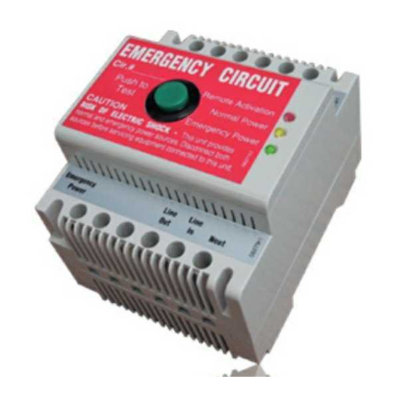
The ELCU-100 Emergency Lighting Control Unit allows lighting control devices for normal lighting to also control emergency lighting
installed within the area. The ELCU is designed for lighting control in areas where emergency lighting fixtures are connected on
dedicated emergency lighting circuits that are typically ON 24 hours per day. The ELCU allows ON/OFF control of the emergency
lighting along with the normal room lighting to save energy.
The intended operation of the ELCU is to guarantee that the emergency lighting is ON whenever normal power to the controlled circuit
is interrupted. While normal power is present, the ELCU allows control of the emergency lighting by a device such as an occupancy
sensor, a relay, a dimmer, or a wall switch.
Important Safeguards
When using electrical equipment always follow basic safety precautions:
• READ AND FOLLOW ALL SAFETY INSTRUCTIONS–SAVE THESE INSTRUCTIONS
• Mount only in an industrial control panel with a DIN rail mounting system.
• Do not use near gas or electric heaters.
• Equipment should be mounted in locations and at heights where it will not readily be subjected to tampering by unauthorized personnel.
• Use of accessory equipment not recommended by the manufacturer may cause an unsafe condition.
• Do not use this equipment for other than intended use.
Control
Normal Line
Device
Normal Neutral
Normal
Line
Neut
In
Power
ELCU-100
Emergency
Power
Emergency Line
Emergency Neutral
Standard wiring for switched control of
emergency lighting along with normal lighting
Wiring Notes
1. You can connect as many NC contacts (including LMTS-100) in series on the jumper loop wire as you want to a single ELCU. You
cannot connect the NC devices in any other manner.
2. At no time can more than 5 ELCU devices can be controlled together by commoning their Test Loop wires to a Normally Closed
Test Switch (LMTS) and/or other NC contact closure.
3. If connecting ELCUs together via their test loop wires, you must maintain the polarity of their wires.
DESCRIPTION AND OPERATION
Normally Closed
Normal
• Test Switch
Lighting
• Fire Alarm Panel
• Security Panel
• Other
Switch
Remote
Remote
In
In
Out +24vdc
Line
Line
Out
In
Neut
Emergency Lighting
Wattstopper
Emergency Lighting Control Unit
Installation Instructions • Instructions d'Installation • Instrucciones de Instalación
Voltages ................................................... 120/277VAC 50/60Hz
Max Load Requirements
Ballast ........................................................ 20A @277VAC
Incandescent .............................................. 10A @120VAC
Motor ......................................................... 1HP @120VAC
Remote Activation .............24VDC sourced, dry contact closure
Integral Control .................................Push-to-Test button on unit
Conformance ........ UL924, NEC, OSHA, NFPA life safety codes
Environment ..................................32º-122ºF (0º-50ºC) Ambient
Terminal Torque .......................4.428 inch pound-force (0.5Nm)
Dimensions ................................................. 2.78" x 3.44" x 2.63"
.................................... (70.61mm x 87.38mm x 66.80mm)
WARNING: TURN THE POWER OFF AT THE
CIRCUIT BREAKER BEFORE WIRING.
WIRING
Normal Line
Normal Neutral
"Sensing"
Line
Normal
Power
ELCU-100
Emergency
Power
Emergency Line
Emergency Neutral
Alternate wiring for dimmer bypass on an emergency circuit
®
SPECIFICATIONS
Dimmer
Normal Lighting
Line
Neut
Switch
Remote
Remote
In
In
In
Out +24vdc
Line
Line
Out
In
Neut
Dimmer
Emergency Lighting
Jumper Wire or
Normally Closed
• Test Switch
• Fire Alarm Panel
• Security Panel
• Other
Advertisement
Table of Contents

Related Manuals for LEGRAND Wattstopper ELCU-100


Summary of Contents for LEGRAND Wattstopper ELCU-100
-
Page 1: Specifications
Wattstopper ® Emergency Lighting Control Unit No: 24868 – 10/17 rev. 1 Installation Instructions • Instructions d’Installation • Instrucciones de Instalación Catalog Number • Numéro de Catalogue • Número de Catálogo: ELCU-100 Country of Origin: Made in China • Pays d’origine: Fabriqué en Chine • País de origen: Hecho en China SPECIFICATIONS Voltages ........... -
Page 2: Installation Procedure
No. 24868 – 10/17 rev. 1 © Copyright 2017 Legrand All Rights Reserved. 800.879.8585 © Copyright 2017 Tous droits réservés Legrand. www.legrand.us/wattstopper © Copyright 2017 Legrand Todos los derechos reservados.
Need help?
Do you have a question about the Wattstopper ELCU-100 and is the answer not in the manual?
Questions and answers