Table of Contents
Advertisement
Quick Links
Advertisement
Table of Contents

Subscribe to Our Youtube Channel
Related Manuals for wtw TriOxmatic 690


Summary of Contents for wtw TriOxmatic 690
- Page 1 Operating manual ® TriOxmatic Dissolved Oxygen Sensor ba25314e04 02/2006...
- Page 2 The latest version of the present operating manual can be found on the Internet under www.WTW.com. © Copyright Weilheim 2006, WTW GmbH Reprinting - even as excerpts - is only allowed with the explicit written authorization of WTW GmbH, Weilheim. Printed in Germany. ba25314e04 02/2006...
-
Page 3: Table Of Contents
® TriOxmatic Contents ® TriOxmatic 690 - Contents Overview ........47 ®... - Page 4 ® Contents TriOxmatic Technical data ....... . 81 General data ........81 Measurement conditions .
-
Page 5: Overview
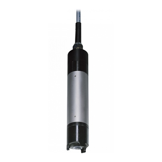
® TriOxmatic Overview Overview ® Structure of the TriOxmatic Fig. 1-1 Structure of the D. O. sensor Protective hood WP 600 membrane cap Electrode unit Shaft Electrode unit: Gold working electrode (cathode) Insulator Silver counter electrode (anode) Reference electrode Recommended fields of application Stationary measurements in water/wastewater applications. - Page 6 ® Overview TriOxmatic ba25314e04 02/2006...
-
Page 7: Safety
® TriOxmatic Safety Safety General information on safety These safety instructions contain all instructions that have to be ® followed for a safe operation of the TriOxmatic 690 D. O. sensor. ® Before starting any work with the TriOxmatic 690, carefully read the safety instructions and strictly follow all protective measures mentioned. -
Page 8: General Safety Instructions
® Safety TriOxmatic General safety instructions Function and The sensor left the factory in a safe and secure technical condition. operational safety The failure-free function and operational safety of the sensor is only guaranteed if the generally applicable safety measures and the special safety instructions in this operating manual are followed during its use. -
Page 9: Commissioning
Note Do not suspend the sensor on the sensor connection cable. Use a sensor holder or armature. Information on this and other ® TriOxmatic 690 accessories is given in the WTW catalog and on the Internet. ba25314e04 02/2006... -
Page 10: Commissioning / Getting The Instrument Ready For Measuring
® Commissioning TriOxmatic Commissioning / Getting the instrument ready for measuring Pull the protective cap off the protective hood of the sensor. Leave the sensor to lie in the air for at least 60 minutes while it is switched on (polarization). Note For the sensor to polarize, the following conditions must be fulfilled: ! The sensor is connected with the measuring transmitter. -
Page 11: Measuring / Operation
Do not suspend the sensor on the sensor connection cable. Use a sensor holder or armature. Information on this and other ® TriOxmatic 690 accessories is given in the WTW catalog and on the Internet. Minimum approach flow The minimum required approach flow at the sensor must be present during measurement (see chapter 7 T ). -
Page 12: Calibration
® Measuring / Operation TriOxmatic Calibration 4.2.1 General information on calibration Why calibrate? During the operation of a D.O. sensor, the slope of the D.O. sensor changes with time. The calibration procedure determines the current slope of the sensor. When to calibrate? Calibrate before measuring and at regular intervals (depending on the application). -
Page 13: Calibration In Water Vapor-Saturated Air
® TriOxmatic Measuring / Operation 4.2.2 Calibration in water vapor-saturated air If necessary, clean the sensor and membrane and dry the membrane (see section 5.2 C LEANING THE SENSOR SHAFT AND MEMBRANE Calibrating position 2 cm Bring the sensor into the calibrating position. To do so, position the sensor approx. -
Page 14: Function Check
® Measuring / Operation TriOxmatic Function check The function check is the simplest way of letting you know whether the sensor needs to be cleaned and calibrated. Note The function check can either be performed in water vapor-saturated air or in air-saturated water. In the case of air temperatures under 5 °C we recommend to perform the function check not in air but in air-saturated water that has a higher temperature. - Page 15 ® TriOxmatic Measuring / Operation Measured values within If the measured value lies within the range of precision required by the the required precision user, no cleaning or recalibrating is necessary. Example: Required precision Measured value in air: 97 % saturation (nominal value: 100%) ⇒...
- Page 16 ® Measuring / Operation TriOxmatic ba25314e04 02/2006...
-
Page 17: Maintenance, Cleaning, Disposal, And Replacement
® TriOxmatic Maintenance, cleaning, disposal, and replacement Maintenance, cleaning, disposal, and replacement General maintenance instructions Warning Contact with the sample can lead to danger to the user! Depending on the type of sample, suitable protective measures must be taken (protective clothing, protective goggles, etc.). Cleaning the sensor shaft and membrane For normal operation (e.g. - Page 18 ® Maintenance, cleaning, disposal, and replacement TriOxmatic Cleaning Pull the sensor out of the sample. Get rid of any coarse contamination on the sensor (e.g. brush it off in a bucket of tapwater, wash it down with a hose or wash it off with a cloth).
- Page 19 ® TriOxmatic Maintenance, cleaning, disposal, and replacement Screw the protective hood back on again. If necessary, carefully dry the membrane with a lint-free paper towel. Calibrate the sensor (see section 4.2 C ALIBRATION ba25314e04 02/2006...
-
Page 20: Changing The Electrolyte And Membrane Cap
Maintenance, cleaning, disposal, and replacement TriOxmatic Changing the electrolyte and membrane cap WTW delivers the sensor ready for operation. The electrolyte solution and membrane cap must only be replaced if: ! a calibration error occurs due to a highly contaminated... - Page 21 ® TriOxmatic Maintenance, cleaning, disposal, and replacement Caution The ELY/A electrolyte solution irritates eyes, skin and mucus membranes. If it comes into contact with the eyes, rinse thoroughly with water and consult a doctor! During working activities, always wear suitable protective gloves and protective goggles/face shield! Follow the safety datasheet.
- Page 22 ® Maintenance, cleaning, disposal, and replacement TriOxmatic Thoroughly rinse the sensor head with electrolyte solution. Fill a new WP 600 membrane cap with ELY/A electrolyte solution (see section 5.8 M AINTENANCE EQUIPMENT AND REPLACEMENT PARTS Throw away the first filling and fill the membrane cap with electrolyte solution once more.
- Page 23 ® TriOxmatic Maintenance, cleaning, disposal, and replacement Remove any air bubbles by carefully tapping the membrane cap. Caution The ELY/A electrolyte solution irritates eyes, skin and mucus membranes. If it comes into contact with the eyes, rinse thoroughly with water and consult a doctor! During working activities, always wear suitable protective gloves and protective goggles/face shield! Follow the safety datasheet.
- Page 24 ® Maintenance, cleaning, disposal, and replacement TriOxmatic Precision Recommendation: In order to carry out precision measurements, leave measurements the sensor to polarize for a longer period of time, e.g. overnight, and recalibrate it the following day. Note In the following cases, you must refill the sensor once more: ! If there are large air bubbles ! If there are air bubbles on the gold working electrode ! For measurements at high water pressure, even if small air bubbles...
-
Page 25: Cleaning The Electrodes
® TriOxmatic Maintenance, cleaning, disposal, and replacement Cleaning the electrodes The counter electrode and reference electrode always show a coloration. This is necessary for the operation of the sensor. This is not contamination. Cleaning is only required in cases of slopes that are too small or too large (the sensor cannot then be calibrated) that cannot be resolved by changing the membrane cap and electrolyte solution. - Page 26 ® Maintenance, cleaning, disposal, and replacement TriOxmatic Rinse the sensor head with tap water. ba25314e04 02/2006...
-
Page 27: Cleaning The Gold Working Electrode
® TriOxmatic Maintenance, cleaning, disposal, and replacement 5.4.1 Cleaning the gold working electrode Moisten the gold working electrode and the SF 300 polishing strip (see section 5.8 M AINTENANCE EQUIPMENT AND ) with deionized water. REPLACEMENT PARTS Using the rough side of the wet SF 300 polishing strip, polish off any contamination from the gold working electrode using light pressure. -
Page 28: Cleaning The Silver Counter Electrode
® Maintenance, cleaning, disposal, and replacement TriOxmatic 5.4.2 Cleaning the silver counter electrode We recommend to clean the silver counter electrode with the RA 600 cleaning attachment that is available as an accessory (see section 5.8 M ). This prevents AINTENANCE EQUIPMENT AND REPLACEMENT PARTS the reference electrode from coming into contact with the cleaning solution. - Page 29 ® TriOxmatic Maintenance, cleaning, disposal, and replacement Remove the screw cap from the safety cap of the cleaning attachment. Fill the screw cap with RL-AG/Oxi cleaning solution (see section 5.8 M AINTENANCE EQUIPMENT AND REPLACEMENT PARTS Screw the sensor with the safety cap onto the screw cap. Leave the cleaning solution for a maximum of 1 hour to take effect.
- Page 30 ® Maintenance, cleaning, disposal, and replacement TriOxmatic Unscrew the screw cap. Thoroughly rinse the electrode unit with the safety cap on with deionized water. Unscrew the safety cap. Rinse the sensor head and electrode unit several times with deionized water. ba25314e04 02/2006...
- Page 31 ® TriOxmatic Maintenance, cleaning, disposal, and replacement Water the sensor head and electrode unit in deionized water for at least an hour. Carefully shake off the drops of water. Fill a new WP 600 membrane cap and screw it on (see section 5.3 C HANGING THE ELECTROLYTE AND MEMBRANE CAP Connect the sensor to the measuring transmitter again.
- Page 32 ® Maintenance, cleaning, disposal, and replacement TriOxmatic Variant 2: Wipe the silver counter electrode with a lint free paper towel Cleaning the silver and carefully remove any loose deposits. counter electrode in a beaker Fill a beaker (150 ml, high-sided form) with approx. 25 ml RL- AG/Oxi cleaning solution.
- Page 33 ® TriOxmatic Maintenance, cleaning, disposal, and replacement Leave the cleaning solution to work for 1 hour. Rinse the sensor head and electrode unit several times with deionized water. Water the sensor head and electrode unit in deionized water for at least an hour. Carefully shake off the drops of water.
-
Page 34: Checking The Sensor For Freedom From Zero-Current
® Maintenance, cleaning, disposal, and replacement TriOxmatic Fill a new WP 600 membrane cap and screw it on (see section 5.3 C HANGING THE ELECTROLYTE AND MEMBRANE CAP Connect the sensor to the measuring transmitter again. After approx. 60 minutes polarization time, the sensor is ready for operation. -
Page 35: Storage
Before disposing of the membrane cap, unscrew it and rinse membrane cap with water. Dispose of the membrane cap in the household refuse. Note To dispose of the chemicals, follow the corresponding safety datasheets. The safety datasheets can be obtained from WTW. ba25314e04 02/2006... -
Page 36: Maintenance Equipment And Replacement Parts
(1 bottle x 50 ml) Polishing film SF 300 203 680 Cleaning attachment for cleaning the RA 600 202 510 counter electrode Note Information on further accessories is given in the WTW catalog and in the Internet. ba25314e04 02/2006... -
Page 37: What To Do If
® TriOxmatic What to do if... What to do if... The sensor is in the air Cause Remedy and the display shows – No electrolyte in the membrane – Change the WP 600 0.0 mg/l or 0% O membrane cap (see section 5.3) The sensor cannot be Cause... - Page 38 ® What to do if... TriOxmatic Measured value Cause Remedy fluctuating heavily – Membrane head loose – Screw the membrane cap tight – Membrane does not fit snugly on – Change the membrane cap, the gold working electrode then recalibrate (see section 5.3 and section 4.2) Incorrect temperature Cause...
-
Page 39: Technical Data
® TriOxmatic Technical data Technical data General data Measuring principle Membrane-covered amperometric sensor with potentiostatically operated 3-electrode system Dimensions Weight (without sensor approx. 660 g connection cable) Membrane Material Fluorine plastic Thickness 50 µm Electrolyte ELY/A Temperature Via integrated NTC, - 5 °C ... + 60 °C measurement Accuracy ±... - Page 40 ® Technical data TriOxmatic Cable gland V4A stainless steel 1.4571 Cable sheath Connection cable Length 1,5 m, 7 m, 15 m (special lengths on request) Diameter 8.6 mm Smallest allowed Permanent bend: 130 mm bend radius Short time bend: 80 mm Instrument safety Applicable norms –...
-
Page 41: Measurement Conditions
® TriOxmatic Technical data Measurement conditions Measuring range D. O. concentration 0.0 ... 60.0 mg/l D. O. saturation 0 ... 600 % ≈ 0 ... 1200 mbar pO Polarization time In the case of re-commissioning or change of At least electrolyte: 60 minutes In the case of short polarization interruptions... -
Page 42: Characteristic Data On Delivery
5 years per electrolyte filling (theoretical electrolyte reserve for operation under air saturation) Electrical data Power supply via WTW measuring transmitter. Connection technique Connection cable permanently mounted on the sensor. Connection to the measuring transmitter via 7-pole screw plug.
Need help?
Do you have a question about the TriOxmatic 690 and is the answer not in the manual?
Questions and answers