wtw TriOxmatic 700 IQ F Operating Manual
Diq/s 181 - d. o. sensor
Hide thumbs
Also See for TriOxmatic 700 IQ F:
- Operating manual (56 pages) ,
- Manual (28 pages) ,
- Operating manual (28 pages)
Table of Contents
Advertisement
Quick Links
Download this manual
See also:
Operating Manual
Advertisement
Table of Contents

Related Manuals for wtw TriOxmatic 700 IQ F


Summary of Contents for wtw TriOxmatic 700 IQ F
- Page 1 OPERATING MANUAL ba77086e01 01/2015 ® TriOxmatic 700 IQ F DIQ/S 181 - D. O. SENSOR...
- Page 2 For the most recent version of the manual, please visit www.WTW.com. Weilheim 2015, WTW GmbH © Copyright Reproduction in whole - or even in part - is prohibited without the express written permission of WTW GmbH, Weilheim. Printed in Germany. ba77086e01 01/2015...
-
Page 3: Table Of Contents
® TriOxmatic 700 IQ F Contents ® TriOxmatic 700 IQ F - Contents ® TriOxmatic 700 IQ F - Inhaltsverzeich- Overview ........5 ®... - Page 4 ® Contents TriOxmatic 700 IQ F Disposal ........34 Maintenance equipment and replacement parts .
-
Page 5: Overview
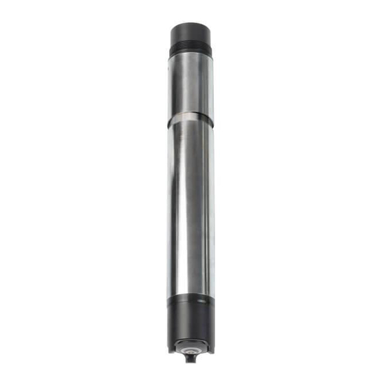
® TriOxmatic 700 IQ F Overview Overview ® Structure of the TriOxmatic 700 IQ F Fig. 1-1 Structure of the D.O. sensor Protective hood WP 600 membrane head Electrode unit Shaft Electrode unit: Gold working electrode (cathode) Insulator Silver counter electrode (anode) Reference electrode Recommended fields of application ®... -
Page 6: Safety
® Safety TriOxmatic 700 IQ F Safety Safety information 2.1.1 Safety information in the operating manual This operating manual provides important information on the safe oper- ation of the product. Read this operating manual thoroughly and make yourself familiar with the product before putting it into operation or working with it. -
Page 7: Safe Operation
® TriOxmatic 700 IQ F Safety Safe operation 2.2.1 Authorized use ® The authorized use of the TriOxmatic 700 IQ F consists of its use as a sensor in the DIQ/S 181. Only the operation and running of the sen- sor according to the instructions and technical specifications given in this operating manual is authorized (see chapter 7 T ECHNICAL DATA... -
Page 8: Commissioning
TION Do not suspend the sensor on the sensor connection cable. Use a sensor holder or armature. Information on this and other DIQ/S 181 accessories is given in the WTW catalog and on the Internet. Minimum approach flow The minimum required approach flow at the sensor must be present during measurement (see chapter 7 T ). -
Page 9: Setting Table For The Trioxmatic
® TriOxmatic 700 IQ F Commissioning For the sensor to polarize, the following conditions must be fulfilled: The sensor is connected to the DIQ/S 181 with the sen- sor cable The DIQ/S 181 is in operation The sensor was identified by the DIQ/S 181. If required, assign a user-defined name to the sensor (see DIQ/ S 181 operating manual). - Page 10 ® Commissioning TriOxmatic 700 IQ F Setting Selection/values Explanation valid Calibration Displays and specifies which calibration data the measured value calculation will be based invalid last valid active valid indicates that a valid calibration is avail- able.
- Page 11 ® TriOxmatic 700 IQ F Commissioning Setting Selection/values Explanation Temp. adjustment -1.5 K ... +1.5 K The temperature compensation enables the tolerances of the temperature sensor to be balanced (shifting of the zero point by ±1.5K). Notes: Due to the thermal capacity of the sensor, it is necessary to place it in a container with at least 2 liters of water.
-
Page 12: Measurement / Operation
® Measurement / operation TriOxmatic 700 IQ F Measurement / operation Measuring CAUTION Contact with the sample can lead to danger to the user! Depend- ing on the type of sample, suitable protective measures must be taken (protective clothing, protective goggles, etc.). For measuring submerse the operable sensor in the test sample. -
Page 13: Calibration In Water Vapor-Saturated Air
® TriOxmatic 700 IQ F Measurement / operation 4.2.2 Calibration in water vapor-saturated air Switch to the measured value display with <M>. Call up calibration with <C>. The next step switches on the maintenance condition for the sensor. A message on this appears on the display. Confirm the message with <OK>. - Page 14 ® Measurement / operation TriOxmatic 700 IQ F Continue with <OK>. The sensor starts the calibration. The display switches to the measured value display. The CAL indicator flashes instead of the main measured value. At the same time, the momentary relative slope flashes as the secondary measured value.
-
Page 15: Reactivating A Valid Calibration
® TriOxmatic 700 IQ F Measurement / operation 4.2.3 Reactivating a valid calibration ® The TriOxmatic 700 IQ F provides a feature with witch you can reac- tivate the last valid calibration if necessary. Thus you can immediately continue to measure if a calibration failed. Reactivating old calibration data is a temporary measure. - Page 16 ® Measurement / operation TriOxmatic 700 IQ F If necessary, clean the sensor and membrane and dry the membrane (see section 5.2 C LEANING THE SENSOR SHAFT AND MEMBRANE Take the sensor out of the measuring solution and position it approx.
- Page 17 ® TriOxmatic 700 IQ F Measurement / operation In the case of air temperatures under 5 °C do not perform the function check in air but in air-saturated water that has a higher temperature. You obtain air-saturated water by pouring water several times in and out of two vessels so that it sparkles.
-
Page 18: Maintenance, Cleaning, Disposal, And Replacement
® Maintenance, cleaning, disposal, and replacement TriOxmatic 700 IQ F Maintenance, cleaning, disposal, and replacement General maintenance notes CAUTION Contact with the sample can lead to danger to the user! Depend- ing on the type of sample, suitable protective measures must be taken (protective clothing, protective goggles, etc.). - Page 19 ® TriOxmatic 700 IQ F Maintenance, cleaning, disposal, and replacement CAUTION Acetic acid irritates the eyes and the skin. When handling acetic acid, always wear protective gloves and protective goggles. NOTE Clean the membrane very carefully! Make sure the membrane is not damaged, e.g. by sharp-edged ob- jects, by laying it on sharp stones, etc.
- Page 20 ® Maintenance, cleaning, disposal, and replacement TriOxmatic 700 IQ F Also clean and rinse the protective hood. Screw the protective hood back on again. If necessary, carefully dry the membrane with a lint-free paper towel. Recalibrate the sensor (see section 4.2 C ALIBRATION ba77086e01 01/2015...
-
Page 21: Exchanging The Electrolyte And Membrane Cap
700 IQ F Maintenance, cleaning, disposal, and replacement Exchanging the electrolyte and membrane cap WTW delivers the sensor ready for operation. The electrolyte solution and membrane head must only be replaced: if the membrane is heavily contaminated and a calibration error occurs (log book message) ... - Page 22 ® Maintenance, cleaning, disposal, and replacement TriOxmatic 700 IQ F Rinse the sensor head with tap water. Carefully rub the silver counter electrode with a paper towel and rinse it with deionized water. Thoroughly rinse the sensor head with electrolyte solution. ba77086e01 01/2015...
- Page 23 ® TriOxmatic 700 IQ F Maintenance, cleaning, disposal, and replacement Fill a new WP 600 membrane cap with ELY/A electrolyte solu- tion (see section 5.8 M AINTENANCE EQUIPMENT AND REPLACE MENT PARTS Throw away the first filling and fill the membrane head once more with electrolyte solution.
-
Page 24: Cleaning The Electrodes
® Maintenance, cleaning, disposal, and replacement TriOxmatic 700 IQ F Screw the membrane head onto the shaft while holding the sensor at an angle. Excess electrolyte solution is forced out of the ventilation area. Ventilation area (see above) The filling should be free of air bubbles as far as possible. How- ever, small air bubbles do not cause any interference. - Page 25 ® TriOxmatic 700 IQ F Maintenance, cleaning, disposal, and replacement NOTE Prior to cleaning the electrodes, disconnect the DIQ/S 181 from the power supply. Otherwise, undesirable electrochemical reactions can occur that may lead to the destruction of the sensor. Preparatory activities Pull the sensor out of the sample and remove any coarse con- tamination from the sensor (e.g.
-
Page 26: Cleaning The Gold Working Electrode
® Maintenance, cleaning, disposal, and replacement TriOxmatic 700 IQ F 5.4.1 Cleaning the gold working electrode Moisten the gold working electrode and the SF 300 polishing strip (see section 5.8 M AINTENANCE EQUIPMENT AND REPLACE ) with deionized water. MENT PARTS Using the rough side of the wet SF 300 polishing strip, polish off any contamination from the gold working electrode using light pressure. -
Page 27: Cleaning The Silver Counter Electrode
® TriOxmatic 700 IQ F Maintenance, cleaning, disposal, and replacement Cleaning the gold working electrode may already be suffi- cient to enable the sensor to be calibrated again. For safety, however, we recommend to also clean the silver counter electrode (see section 5.4.2) and to use a new membrane cap afterwards. - Page 28 ® Maintenance, cleaning, disposal, and replacement TriOxmatic 700 IQ F Screw the cleaning attachment onto the sensor, instead of the membrane head. NOTE Never grease or lubricate the inner O-ring in the RA 600 cleaning at- tachment! Remove the screw cap from the safety cap of the cleaning attachment.
- Page 29 ® TriOxmatic 700 IQ F Maintenance, cleaning, disposal, and replacement Leave the cleaning solution to take effect for a maximum of 1 hour. Unscrew the screw cap. Thoroughly rinse the electrode unit with the safety cap on with deionized water. Unscrew the safety cap.
- Page 30 ® Maintenance, cleaning, disposal, and replacement TriOxmatic 700 IQ F Rinse the sensor head and the electrode unit several times with deionized water. Rinse the sensor head and the electrode unit for at least an hour in deionized water. Carefully shake off the drops of water. ba77086e01 01/2015...
- Page 31 ® TriOxmatic 700 IQ F Maintenance, cleaning, disposal, and replacement Fill a new WP 600 membrane cap and screw it on (see section 5.3 E XCHANGING THE ELECTROLYTE AND MEMBRANE CAP Reconnect the DIQ/S 181 with the power supply. Leave the sensor to lie in the air for at least 60 minutes while it is switched on (polarization).
- Page 32 ® Maintenance, cleaning, disposal, and replacement TriOxmatic 700 IQ F NOTE The reference electrode must not come into contact with the cleaning solution under any circumstances. This could destroy the reference electrode and cause the sensor to become defective. Clamp the sensor in a stand. Submerse the electrode unit in the RL-AG/Oxi cleaning solu- tion to just above the silver counter electrode.
-
Page 33: Checking The Sensor For Freedom From Zero-Current
® TriOxmatic 700 IQ F Maintenance, cleaning, disposal, and replacement Rinse the sensor head and the electrode unit for at least an hour in deionized water. Carefully shake off the drops of water. Fill a new WP 600 membrane cap and screw it on (see section 5.3 E XCHANGING THE ELECTROLYTE AND MEMBRANE CAP Reconnect the DIQ/S 181 with the power supply. -
Page 34: Storage
® Maintenance, cleaning, disposal, and replacement TriOxmatic 700 IQ F Test solution 1 g/l aqueous sodium sulfite solution, Na (addition of 1 mg/l of a cobalt(II) salt accelerates the removal of oxygen from the solution.) The sensor should be in operation for at least 1 hour before the inspec- tion. -
Page 35: Maintenance Equipment And Replacement Parts
Dispose of the membrane head in the household refuse. To dispose of the chemicals, follow the relevant safety datasheets. The safety datasheets can be obtained from WTW. Maintenance equipment and replacement parts Description Model Order no. -
Page 36: What To Do If
® What to do if... TriOxmatic 700 IQ F What to do if... Cause Remedy The sensor is in the air No electrolyte in the membrane Change the WP 600 mem- and the display shows head brane cap (see section 5.3) 0.0 mg/l or 0% O The sensor cannot be Cause... - Page 37 ® TriOxmatic 700 IQ F What to do if... Measured value Cause Remedy fluctuating heavily Screw the membrane head Membrane head loose tight Membrane does not fit snugly on Change the membrane cap, the gold working electrode then recalibrate (see section 5.3 and section 4.2) Measured values too Cause...
-
Page 38: Technical Data
® Technical data TriOxmatic 700 IQ F Technical data Measuring characteristics Measuring principle Membrane-covered amperometric sensor with potentiostatically oper- ated 3-electrode system; Integrated microprocessor electronics, shielded 2-wire connection for power and data transmission. Electrolyte ELY/A Measuring ranges and Measuring mode Measuring range Resolution resolution... -
Page 39: Application Characteristics
® TriOxmatic 700 IQ F Technical data Application characteristics Allowed temperature Measuring medium 0 °C ... + 60 °C (32 ... 140 °F) range Storage/transport - 5 °C ... + 65 °C (23 ... 149 °F) Allowed pH range of the 4 ... -
Page 40: Electrical Data
® Technical data TriOxmatic 700 IQ F Insulator PEEK Protective hood * Stainless steel can be corrodible if there are chloride concentrations of 500 mg/L or more. Automatic sensor SensReg Electrolyte solution depleted monitoring SensLeck Membrane head leaking (SensCheck function) Instrument safety Applicable norms –... -
Page 41: Indexes
® TriOxmatic 700 IQ F Indexes Indexes Explanation of the messages This chapter contains a list of all the message codes and related mes- ® sage texts for the TriOxmatic 700 IQ F sensor. Information on the contents and structure of the log book and ... -
Page 42: Informative Messages
* Power supply module overloaded * Check terminal and module connections * Defective component, replace components Component hardware defective * Contact WTW SensReg: Electrolyte supply is depleted * Change electrolyte solution and membrane head immediately (see operating manual) SensLeck: Membrane head damaged... - Page 44 For more information on how Xylem can help you, go to xyleminc.com. ® Service address: Xylem Analytics Germany Sales GmbH & Co. KG Dr.-Karl-Slevogt-Str. 1 82362 Weilheim Germany Tel.: +49 881 183-325 Fax: +49 881 183-414 E-Mail wtw.rma@xyleminc.com Internet: www.WTW.com Xylem Analytics Germany GmbH Dr.-Karl-Slevogt-Str. 1 82362 Weilheim Germany...
Need help?
Do you have a question about the TriOxmatic 700 IQ F and is the answer not in the manual?
Questions and answers