
Related Manuals for YASKAWA PVI 36TL


Summary of Contents for YASKAWA PVI 36TL
- Page 1 PVI 36TL INSTALLATION AND OPERATION MANUAL Revision H © 2017, Yaskawa – Solectria Solar...
- Page 2 PVI 36TL Installation and Operation Manual (Rev H) IMPORTANT REGISTRATION AND WARRANTY INFORMATION For warranty to become active, this inverter must be registered. To activate warranty and register inverter, please visit the link below. www.solectria.com/registration DOCR-070588-H Page 2 of 120...
-
Page 3: Before You Start
Before You Start… This manual contains important information regarding installation and safe operation of the PVI 36TL. Be sure to read this manual carefully before using the inverter. Thank you for choosing a Solectria grid-tied PV Inverter. This PV Inverter is high performance and highly reliable product specifically designed for the North American Solar market. -
Page 4: Important Safety Instructions
PVI 36TL Installation and Operation Manual (Rev H) IMPORTANT SAFETY INSTRUCTIONS SAVE THESE INSTRUCTIONS Please read this user manual carefully before product installation. Solectria reserves the right to refuse warranty claims for equipment damage if the user fails to install the equipment according to the instructions in this manual. - Page 5 Do not operate or maintain the inverter until at least 5 minutes has passed after disconnecting all sources from DC and AC sides. CAUTION: PVI 36TL inverter is approx. 66kg (145 pounds) including the wiring box. Please ensure the mounting bracket is properly installed before hanging the inverter on the bracket.
-
Page 6: Table Of Contents
PVI 36TL Installation and Operation Manual (Rev H) BEFORE YOU START… ................ 3 IMPORTANT SAFETY INSTRUCTIONS ............4 1.0: OVERVIEW ..................9 1.1 I PV S ..........9 NVERTER FOR YSTEMS 1.2 P ............... 9 RODUCT EATURES 1.3 P ..........10... - Page 7 PVI 36TL Installation and Operation Manual (Rev H) 4.1 D LCD ..............72 ESCRIPTION OF 4.2 O ................ 73 PERATION TATE 4.3 I ................73 NTERFACE YPES 4.4 M ................ 75 ENU FUNCTIONS 4.4.1 Operation information ..............75 4.4.2 Alarm ..................77 4.4.3 History ..................78...
- Page 8 PVI 36TL Installation and Operation Manual (Rev H) 10.0: APPENDICES: ................. 115 A – I ......115 PPENDIX NSTRUCTION OF NVERTER ELECTION B – PVI 36TL D ........... 119 PPENDIX ATASHEET C – S ............ 119 PPENDIX TRING IZING D – C ..........
-
Page 9: Overview
1.0: Overview 1.1 Inverter for Grid-Tied PV Systems The PVI 36TL inverter is suitable for use for commercial and large scale PV grid-tied systems. A system is generally made up of PV modules, DC power distribution equipment, PV inverter and AC power distribution equipment (Figure 1.1). -
Page 10: Product Protection Functions
Monitoring of IGBT module temperature 1.4 Circuit Structure Design The basic schematic diagram of PVI 36TL inverter is shown in Figure 1.2. The input of PV modules passes through surge protection circuitry, DC EMI wave filter, and the front-end boost circuitry to achieve maximum power tracking and boost up voltages. -
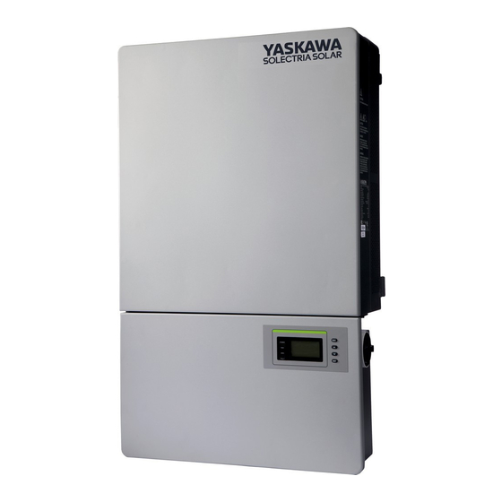
Page 11: Appearance Description
PVI 36TL Installation and Operation Manual (Rev H) 1.5 Appearance Description Figure 1.3 - Sketch of PVI 36TL Inverter Main Items of the Inverter: 1) Main inverter section 2) Wiring box of the inverter 3) Mounting bracket 4) External cooling fans... -
Page 12: Anti Islanding
1.7 DC Ground Fault Protection The PVI 36TL includes residual current detection as part of the DC ground fault detection method as required by UL1741. If there is a ground fault in the array, the ground fault detection technology will detect the array leakage current. The inverter will shut down if the leakage current exceeds 500mA. - Page 13 PVI 36TL Installation and Operation Manual (Rev H) Table 2.1 - Main Items Item Note Main inverter section Wiring box Upon which inverter is hung and Mounting bracket mounted onto a wall User manual Installation and operation manual Accessory kit...
-
Page 14: Recommendations Before Installation
PVI 36TL Installation and Operation Manual (Rev H) ferrule for AC side (4 AWG) Pre-insulated ferrule for grounding For AC ground cables (8AWG) Pre-insulated (10) ferrule for DC side For DC input cables (10 AWG) For RS-485 or Ethernet communication,... -
Page 15: Mechanical Installation
PVI 36TL Installation and Operation Manual (Rev H) 2.2 Mechanical Installation 1) Dimensions Figure 2.1 - PVI 36TL Inverter Dimensions DOCR-070588-H Page 15 of 120... - Page 16 PVI 36TL Installation and Operation Manual (Rev H) 2) Installation Method (see Figure 2.2): Make sure that the mounting structure (wall, rack, etc.) is suitable to support the inverter weight. Follow the mounting guidelines below: (a) If the location permits, install the inverter vertically.
- Page 17 PVI 36TL Installation and Operation Manual (Rev H) 3) Installation Space Requirement (see Figure 2.3): The distances between the inverters or the surrounding objects should meet the following conditions: NOTICE: The spacing between two adjacently mounted inverters should be ≥500mm (19.7 inches). Ensure that the air space around the inverter is well ventilated.
- Page 18 PVI 36TL Installation and Operation Manual (Rev H) 7.9in ¡ Ý 2 00mm 23.6in ¡ Ý 6 00mm 11.8in ¡ Ý 3 00mm 11.8in 11.8in ¡ Ý 3 00mm ¡ Ý 3 00mm Figure 2.4 - Inverter Pillar Mounting Specifications...
- Page 19 PVI 36TL Installation and Operation Manual (Rev H) 4) Mounting the Inverter Onto the Bracket (1) Mark the 8 holes on the bearing surface for mounting the bracket as shown in Figure 2.5; 550mm(min.) 250mm 250mm (21.7in.) (9.84in.) (9.84in.) 1100mm(min.) (43.3in.)
- Page 20 Figure 2.8, and mount the inverter onto the bracket. CAUTION: The main PVI 36TL inverter section is 55kg (≈122 pounds). Please ensure the mounting bracket is properly installed before hanging the inverter on the bracket. It is recommended to have at least 2 people to mount the inverter due to the weight of the equipment.
- Page 21 PVI 36TL Installation and Operation Manual (Rev H) Figure 2.8 - Grab Handle Position (4) Installing the wiring box ① Remove the cover plate at the bottom of the main section. (see Figure 2.9) Tool: No.2 Phillips head screwdriver Figure 2.9 – Main Section Cover Plate ②...
- Page 22 Tool: No. 10 Wrench, torque value of 25 in-lbs (2.8N.m ) Figure 2.11 - Wiring Box Installation CAUTION: The total weight of the PVI 36TL main inverter section and wiring box is 66kg (146 pounds). DOCR-070588-H Page 22 of 120...
- Page 23 PVI 36TL Installation and Operation Manual (Rev H) (5) Attach the main section and the wiring box to the mounting bracket with the M5x10 bolts (6 pcs). (see Figure 2.12) Tool: No.2 Phillips head screwdriver, torque value of 1.6N.m (14 in-lbs) Figure 2.12 - Secure the Main Section and Wiring Box to the Bracket...
- Page 24 PVI 36TL Installation and Operation Manual (Rev H) Figure 2.13 - Anti-Theft Padlock Location The anti-theft padlock should meet the requirement of the dimensions shown in Figure 2.14: Recommended lock size: A: Ф3~6mm B: 20~50mm C: 20~50mm Figure 2.14 - Dimensions of Anti-Theft Padlock...
- Page 25 PVI 36TL Installation and Operation Manual (Rev H) Figure 2.15 – Removing the Wiring Box Cover (2)To replace the cover use a #3 Phillips screwdriver to replace the 4 screws on the cover. INSTRUCTION: It is important to use a hand tool (e.g. Screwdriver or T-handle, #3 Phillips) and not power drivers or other types of screw drivers.
-
Page 26: Electrical Installation
PVI 36TL Installation and Operation Manual (Rev H) 2.3 Electrical Installation The connection interface of PVI 36TL inverter: Figure 2.16 - Full View of Wiring Box with Options Figure 2.17 - External Connection Ports DOCR-070588-H Page 26 of 120... - Page 27 PVI 36TL Installation and Operation Manual (Rev H) Figure 2.18 - Internal Connection Points 1. Knockout for DC input cable, 1-1/4inch 2. Knockout for AC output cable, 1-1/4inch 3. Knockout for communication cable, 3/4inch 4. External ground connection point 5, Side knockout for DC input cable,1-1/4inch 6.
-
Page 28: Dc Connection
2.3.1 DC Connection 1) Working Mode PVI 36TL inverter has two PV input sections: DC Input-1 and DC Input-2. These two sections can work in “Parallel mode” or “Independent mode” (see Figure 2.20). The default setting from the factory is “Parallel mode”. - Page 29 PVI 36TL Installation and Operation Manual (Rev H) Inverter Inverter Input-1 Input-2 Input-1 Input-2 n1=n2 n3=n4 n1=n2 =n3=n4 Figure 2.20(a) - Parallel Mode Figure 2.20(b) - Independent Mode Table 2.4 - DC Input Power Specification (Parallel mode- PVI 36TL Default from...
- Page 30 PVI 36TL Installation and Operation Manual (Rev H) Figure 2.21(a) Jumper busbar Figure 2.21(b) DOCR-070588-H Page 30 of 120...
- Page 31 Figure 2.22 – PV Connection Mode Selector Switch Location 2) DC Fuse Configuration PVI 36TL inverters are equipped with standard 15A DC fuses. Customers must verify that the appropriate fuses are installed depending on the actual configuration of PV strings.
- Page 32 PVI 36TL Installation and Operation Manual (Rev H) (a) Each independent string of DC input from the PV strings needs fuse protection. (b) The rated voltage of fuses should 1000V (c) The rated current of fuses is generally 1.56 × short circuit current from the PV strings, rounded up to the next available fuse size.
- Page 33 PVI 36TL Installation and Operation Manual (Rev H) 3) DC Cable Connection To ensure the optimum performance of the inverter, please read the following guidelines before DC connection: (a) Confirm the DC configuration referring to Table 2.5 and ensure that the maximum open circuit voltage of the PV modules is lower than 1000 VDC under any conditions.
- Page 34 PVI 36TL Installation and Operation Manual (Rev H) Use of Bypass 2 AWG 50 in-lbs Bypass terminal terminal *Consider combining MPPT zones for such configurations (d) Check the polarity (Figure 2.23) before plugging the DC connectors with the cables of PV strings according to the following steps: i.
- Page 35 PVI 36TL Installation and Operation Manual (Rev H) (g) Connect the crimped DC cables to the terminal block on the circuit board and fasten the screws, as shown in Figure 2.25: Tools: 6mm (0.23in.) flat screwdriver Torque value: 3.4N-m (30 in-lbs) Figure 2.25(a) - DC Input Cable Specifications...
- Page 36 PVI 36TL Installation and Operation Manual (Rev H) Independent mode can be very helpful for sites with shading on parts of the array. However, this also means that one must consider these two zones as two separate inverters and power must be balanced as much as possible between the two MPPT zones.
-
Page 37: Ac And Ground Connection
PVI 36TL Installation and Operation Manual (Rev H) Note 1: The temperature rating of the input wirings should be no less than 90°C (194°F). Note 2: The recommended fuse types are configured according to the condition that the input strings are the same. - Page 38 PVI 36TL Installation and Operation Manual (Rev H) Table 2.7 - Required Tools Tools #3 Phillips screwdriver 1/4” flat head bit 1/8” flat head bit Torque driver Diagonal pliers Wire stripping pliers Crimping pliers Table 2.8 - Torque Values AC output terminal block 30 in-lbs (3.5 N-m )
- Page 39 PVI 36TL Installation and Operation Manual (Rev H) (1) Connect the AC (L1, L2, L3, N) cables to the terminal block and use the OT type terminal to connect the ground cable to the internal grounding stud inside the wiring box. (see the 2 graph in Figure 2.27) Set up the cables referring to Figure 2.29.
- Page 40 PVI 36TL Installation and Operation Manual (Rev H) (3) When the output of the inverter is connected to the grid, an external AC circuit breaker is required to be installed to safely disconnect the inverter from the grid when overcurrent occurs.
-
Page 41: Inverter Communication Connections
PVI 36TL Installation and Operation Manual (Rev H) 2.4 Inverter Communication Connections The PVI 36TL inverters support industry standard Modbus RS-485 communications. Figure 2.32 - Communication/LCD and component locations inside the inverter Wiring Box DOCR-070588-H Page 41 of 120... - Page 42 PVI 36TL Installation and Operation Manual (Rev H) Item Picture Configuration description P205 - Dry Contact Communication Port (3 Pin Connector) Please see section 2.4.3 Dry contact communication for more details. N.O. N.C. COM P207 - USB port Reserved for factory use...
-
Page 43: Third Party Monitoring Systems Modbus Connections
PVI 36TL Installation and Operation Manual (Rev H) 2.4.1 Third Party Monitoring Systems Modbus Connections The PVI 36TL inverter can be connected to a third party Data Acquisition System (DAS) via Modbus (RS-485) connection as shown in figure 2.33. Figure 2.33 - PVI 36TL Inverters in a Modbus (RS-485) Daisy Chain Connected to a third party DAS ... - Page 44 PVI 36TL Installation and Operation Manual (Rev H) Star or T Modbus (RS-485) network topologies should always be avoided. See Figure 2.34. Figure 2.34 It is important to daisy chain the inverter Modbus (RS-485) connections to minimize noise and bus reflections. Any network topologies shown to the left should be avoided.
- Page 45 PVI 36TL Installation and Operation Manual (Rev H) Connecting third party DAS Modbus (RS-485) Network to the PVI 36TL Inverter: Warning: Risk of Electric Shock. Make sure all DC and AC power to the unit has been disconnected before opening the inverter wiring box and make sure hazardous high voltage and energy inside the equipment has been discharged.
- Page 46 PVI 36TL Installation and Operation Manual (Rev H) Figure 2.36 The above image shows the Modbus (RS-485) cable connection where the Modbus daisy chain ends. Notice how the cable shield is not landed inside the inverter. The Modbus termination switch (S402) is in the on position.
- Page 47 PVI 36TL Installation and Operation Manual (Rev H) IMPORTANT: The cable shield should only be connected to ground (GND) at the third party DAS. Do not connect the shield to any of the inverters Figure 2.37 Notice how the cable shield is daisy chained together and not landed inside the inverter.
-
Page 48: Solrenview Data Logger Modbus Connections
PVI 36TL Installation and Operation Manual (Rev H) 2.4.2 SolrenView Data Logger Modbus Connections The SolrenView Data loggers are installed externally as shown in figure 2.38a, 2.38b and is shipped with an external weathertight box and a combination power and Modbus cable. - Page 49 PVI 36TL Installation and Operation Manual (Rev H) Figure 2.38a - Typical PVI 36TL Network Connections Utilizing SolrenView Data Logger and Veris Revenue Grade Meter. DOCR-070588-H Page 49 of 120...
- Page 50 PVI 36TL Installation and Operation Manual (Rev H) Figure 2.38b - Typical PVI 36TL Network Connections Utilizing SolrenView Data Logger, Veris Revenue Grade Meter, Central Inverter and a Weather Station. DOCR-070588-H Page 50 of 120...
- Page 51 2 or up to 32 devices connected to the bus. The Modbus termination resistors are built into the PVI 36TL inverter which can be turned on by flipping switch S402 to the ON position as shown in Figure 2.35. The S402 switch should always be left in the OFF position except for the last inverter in the daisy chain.
- Page 52 PVI 36TL Installation and Operation Manual (Rev H) Installing the SolrenView Data Logger: Install the SolrenView data logger and its weathertight box next to the first inverter in the daisy chain. The SolrenView data logger is powered by the inverter and needs to be connected to the first inverter in the Modbus daisy chain.
- Page 53 PVI 36TL Installation and Operation Manual (Rev H) Connect the supplied SolrenView data logger power and Modbus cable to the logger as shown in Figure 2.40. The SolrenView data logger is shipped from the factory with the Modbus termination resistors in the ON position. See DIP switches #3 and #4 closest to the white Molex connector on SW1 in Figure 2.41a.
- Page 54 PVI 36TL Installation and Operation Manual (Rev H) Figure 2.41b - The SolrenView Data Logger Printed Circuit Board and the Modbus Termination Dip Switches. Rev 4 or newer board. Note: Switches 3 and 4 have been removed from Rev 4 and newer boards and are no longer applicable on rev 4 and newer boards.
- Page 55 Disconnect all inverter AC and DC power. Open the inverter wiring box. Bring the Yaskawa Solectria Solar supplied SolrenView data logger power and Modbus cable into the inverter wiring box through knockout holes at the bottom. See section 2.3 Electrical Installation for more information. Connect the cable to P208 on the LCD board as shown in Figure 2.43.
- Page 56 PVI 36TL Installation and Operation Manual (Rev H) Figure 2.43 - The SolrenView Data Logger is connected to the PVI 36TL inside the Wiring Box. DOCR-070588-H Page 56 of 120...
- Page 57 PVI 36TL Installation and Operation Manual (Rev H) If the inverter is the last/only Modbus device in the Modbus daisy chain, make sure the Modbus termination switch S402 is in the ON position (Up towards the LCD) enabling the Modbus termination resistor. Do not turn the switch to the ON position in any of the other inverters.
-
Page 58: Preparing The Inverter For Modbus Communications
PVI 36TL Installation and Operation Manual (Rev H) 2.4.3 Preparing the Inverter for Modbus Communications To ensure correct Modbus communications with the SolrenView data logger, each inverter Modbus communications settings need to be configured properly. Please follow the steps below to adjust the inverter Modbus ID and Modbus Baud rate. -
Page 59: Preparing The Solrenview Logger
The SolrenView data logger is shipped from the factory with default setting to auto discover Yaskawa Solectria Solar inverters and supported RGMs. The SolrenView logger should be connected to all the devices before it is turned on as described in above sections for the auto discovery to work. - Page 60 PVI 36TL Installation and Operation Manual (Rev H) Internet Gateway Configuration: The Internet Gateway should not require any special configuration as most routers are already configured to support DHCP discovery and to allow outgoing traffic. In case the router/firewall is configured to restrict outgoing traffic, an outgoing rule must be added to allow the logger to connect to the SolrenView Monitoring data servers.
-
Page 61: Connecting Revenue Grade Meter To The Solrenview Logger
PVI 36TL Installation and Operation Manual (Rev H) 2.4.5 Connecting Revenue Grade Meter to the SolrenView Logger Warning: Risk of Electric Shock. Make sure all DC and AC power has been disconnected before starting any work. Some installations require Revenue Grade Metering (RGM) for accurate energy production tracking and reporting. - Page 62 PVI 36TL Installation and Operation Manual (Rev H) Choose a unique Modbus ID (address) different from any Inverter Modbus ID and set the switches for that ID as shown in Figure 2.45. Only Modbus IDs 1 through 32 can be used.
- Page 63 PVI 36TL Installation and Operation Manual (Rev H) Connect the voltage leads to the phase conductors at a location that is not normally turned off. Connect voltage leads on the Line side of the conductor to ensure constant power to the RGM.
- Page 64 PVI 36TL Installation and Operation Manual (Rev H) Snap the CT onto the conductor. Connect CTs to the correspondingly colored voltage leads. If the application can exceed 20 times the rated CT current, use wire ties to secure the I-bar to the CT housing.
-
Page 65: Dry Contact Communication
PVI 36TL Installation and Operation Manual (Rev H) 2.4.6 Dry Contact Communication The inverter features an alarm function that opens or closes a dry contact on the communication board. (available both as contact normally open – N.O. – and as contact normally closed –... - Page 66 PVI 36TL Installation and Operation Manual (Rev H) Connection Plan: You can connect a LED or other loads to indicate the operational status of the inverter, as shown in the following figure: (or L (or L Line circuit Breaker( 3 A) Line circuit Breaker( 3 A) N.C.
- Page 67 PVI 36TL Installation and Operation Manual (Rev H) Tool: Wire stripping pliers Figure 2.49 - Wire Stripping Table 2.13 Cable Set-Up Position Description Value Cable type Double-layer insulated cable Outer diameter 4.5 mm~ 6 mm Cross-section area of conductor 0.2 mm² ~ 0.75 mm²...
- Page 68 PVI 36TL Installation and Operation Manual (Rev H) e.) Plug the cable terminal into the P205 connector. Figure 2.51 - Dry Contact Communication Cable Connection DOCR-070588-H Page 68 of 120...
-
Page 69: Commissioning
PVI 36TL Installation and Operation Manual (Rev H) 3.0: Commissioning WARNING: Please follow the guidelines below before on-grid operation to eliminate possible dangers and to ensure safety. 3.1 Commissioning Checklist 3.1.1 Mechanical Installation Make sure that the mounting bracket is secure and all the screws have been tightened to the specified torque values. - Page 70 PVI 36TL Installation and Operation Manual (Rev H) (e) When the inverter completes “sys checking”, the LCD shows the screen as Figure 3.1 below. Press ENTER to the standard selection interface, as shown in Figure 3.2. Select the corresponding grid standard and press ENTER.
- Page 71 PVI 36TL Installation and Operation Manual (Rev H) (g) When the LCD shows the normal operation status (Figure 3.3) and the “RUN” light on the LED panel lights up, it indicates that the grid connection and power generation are successful.
-
Page 72: User Interface
PVI 36TL Installation and Operation Manual (Rev H) 4.0: User Interface 4.1 Description of LCD The inverter’s LCD mainly consists of LCD, LED indicator lights, buzzer and 4 keys, as shown in Figure 4.1. POWER GRID FAULT Figure 4.1 - LCD Interpretation for the indicator lights is shown in Table 5-1 and function of the keys is shown in Table 4.2. -
Page 73: Operation State
PVI 36TL Installation and Operation Manual (Rev H) Light Indicates a Fault Slow Indicates Alarm (light on 0.5s, light off Fault flash status FAULT indication Fast Protective action (light on 0.5s, light off light flash 0.5s) Light No fault or power supply not working Table 4.2 - Definition of the Keys... - Page 74 PVI 36TL Installation and Operation Manual (Rev H) (1) The LCD interface starts with the company logo once the system is energized, as shown in Figure 4.2. Figure 4.2 - Logo Screen (2) Indication of inverter operation mode: Sys.Checking >>>>>>...
-
Page 75: Menu Functions
PVI 36TL Installation and Operation Manual (Rev H) GridV.OutLim Figure 4.6 - Fault Indication Interface LCD will display different mode interfaces based on the operation modes of the inverter. There are four operation modes: startup system check mode (as shown in Figure 4.3), stand-by mode (as shown in Figure 4.4), normal operation mode (as... - Page 76 PVI 36TL Installation and Operation Manual (Rev H) EDay 23.5kWh 1 OP.Info PDayPk 19kW DayT 12 .1 h 480.2V 480.5V 479.7V Freq 60.0Hz 20.1A 19.8A 20.0A Tmod 78.2C Tamb 50.1C Upv 1 452.0V Ipv1 18.9A Upv 2 453.4V Ipv2 18.7A 16.8KVA...
-
Page 77: Alarm
PVI 36TL Installation and Operation Manual (Rev H) 4.4.2 Alarm As previously noted, if a fault occurs during normal operation of the inverter, corresponding fault messages will be indicated in “2 Alarm” menu in addition to the sound and light alarms. Move the cursor to “2 Alarm” and press ENT to check out the specific fault information, as shown in Figure 4.10. -
Page 78: History
PVI 36TL Installation and Operation Manual (Rev H) 4.4.3 History Move the cursor to “3 History” in the main interface. Press ENT to check the history information, as shown in Figure 4.11. There are 4 submenus in “3 History”: “1 HistErr”, “2 OP. -
Page 79: System Configuration
PVI 36TL Installation and Operation Manual (Rev H) 4.4.4 System Configuration Move the cursor to “4 Setting” in the main interface. Press ENT to enter the password: UP -> DOWN -> UP -> DOWN. Press ENT to confirm, and set the current system parameters, as shown in Figure 5-12. - Page 80 PVI 36TL Installation and Operation Manual (Rev H) The inverter will stand by instead of working normally if the startup conditions do not meet the needed values even if “ON” is selected. The inverter will shut down immediately if “OFF” is selected in any case.
-
Page 81: Power Dispatch
PVI 36TL Installation and Operation Manual (Rev H) interface if the MPPT scanning succeeds, or remain on the “MPPTScan menu” interface if the scanning fails. (7) Configure the network address in the “7 NetConfig” menu. Move the cursor to the menu, press ENT and set up the parameters by UP and DOWN. - Page 82 PVI 36TL Installation and Operation Manual (Rev H) Figure 4.14 - System Protection Parameter Configuration (1) The system protection parameters of each grid standard can be set up in “1 SysPara” menu. Please refer to Section 4.4.7. (2) “2 Restart” menu: If a fault shutdown arises, a severe fault may have occurred inside the inverter.
-
Page 83: System Control Parameters
Shutdown” to turn off the inverter. INSTRUCTION: PVI 36TL PV inverter supports 4 grid standards. Please check with your local electricity supply company before selecting the grid standard. If the inverter is operated with a wrong grid standard, the electricity supply company may cancel the interconnection agreement. - Page 84 PVI 36TL Installation and Operation Manual (Rev H) Recovery threshold value of GridVmaxRecT(V) {200.0, 518.0, 533.0} Max. grid voltage Recovery threshold value of GridVminRecT(V) {0, 432.4, 480.0} Min. grid voltage Recovery time of grid voltage GridVRecT(S) {0, 300.00, 600.00} protection Protection threshold value of GridF.Max1(Hz)
- Page 85 PVI 36TL Installation and Operation Manual (Rev H) SoftOffOption Soft turn off option {Disable, Disable, Enable} OffPStep(KW/S) Turn off power step {0.01, 2.16,2.88} IsoResis(KOhm) Isolation resistance {10.0, 250.0 1000.0} GridReStep(KW/S) Grid fault recovery step {0.01, 0.05, 2.88} (3) ”4 PowerContr” menu: relative functions of active, reactive power control and...
- Page 86 PVI 36TL Installation and Operation Manual (Rev H) INSTRUCTION: The PF (P) Curve function is only available for VDE-4105, CEI 0-21 and IEEE-1547 grid standards. (PFCurveP1,PFCurvePF1) Inductive (P%) Capacitive (PFCurveP2,PFCurvePF2) Figure 4.16 - PF(P) Curve Mode 6). Q(U) Curve:Q(U) curve mode Note: The reactive compensation changes according to the grid voltage change, as shown in Figure 4.17.
- Page 87 PVI 36TL Installation and Operation Manual (Rev H) Q(%) (QuCurveU2i,QuCurveQ2i) Inductive (QuCurveU1, QuCurveQ1) (QuCurveU1i, U(V) QuCurveQ1i) Capacitive (QuCurveU2,QuCurveQ2) Figure 4.17 - Q(U) Curve Mode The Table 5-5 lists the parameters of QReactSet, PF Set, PF(P) Curve and Q(U) Curve modes. Press ENT to start up the modes after the parameters are set up.
- Page 88 PVI 36TL Installation and Operation Manual (Rev H) QuCurveQ2(%) (-100.0%, -50.0%, 100.0%) See Figure 5-18 QuCurveU1i(V) (422.4, 441.6, 480.0) See Figure 5-18 QuCurveQ1i(%) (-100.0%, 0.0%, 100.0%) See Figure 5-18 QuCurveU2i(V) (422.4, 432.0, 480.0) See Figure 5-18 QuCurveQ2i(%) (-100.0%, 50.0%, 100.0%)
-
Page 89: Arc Fault Current Interruption
PVI 36TL Installation and Operation Manual (Rev H) 4.4.8 Arc Fault Current Interruption PVI 36TL is embedded with Type 1 DC arcing fault current detection device which stops the inverter from working when arcing fault current is detected on the DC side and shows “ARC Protect”... - Page 90 PVI 36TL Installation and Operation Manual (Rev H) In the “System Setting””OtherCmd” menu, execute “ARCFaultClear” command to clear “ARC Protect” fault alarm, and LCD will show “Succeed” if the fault is successfully cleared, as shown in Figure 4.21. AFCIOperation Enable...
-
Page 91: Operation
PVI 36TL Installation and Operation Manual (Rev H) 5.0: Operation 5.1 Start-up Manual Start-up: Manual start-up is required after regulation setting or manual (fault) shut-down. Move the cursor from the main operation interface to “4 Setting”. Press ENT and go to submenu “1 ON/OFF”. Then move the cursor to “ON” and press ENT to start the inverter. - Page 92 PVI 36TL Installation and Operation Manual (Rev H) V A C V A C 480 V 400 V 12.5 A 15.1 A 80.2 80.2 08/12 13:10:10 08/12 13:10:05 Figure 5.2 - Default Indication Interface for Normal Operation In this mode, the inverter converts the power generated by PV modules to AC continuously and feeds into the power grid.
-
Page 93: Grid-Tied Power Generation
DC and AC. 5.4 Grid-Tied Power Generation PVI 36TL series inverter has an automatic grid-tied power generation process. It will check whether AC power grid meets the conditions for grid-tied power generation constantly, and test whether the PV array has enough adequate energy. After all conditions are met, the inverter will enter grid-tied power generation mode. -
Page 94: Maintenance And De-Installation
PVI 36TL Installation and Operation Manual (Rev H) 6.0: Maintenance and De-Installation 6.1 Fault Shutdown and Troubleshooting 6.1.1 LED Fault and Troubleshooting When contacting Solectria for support please provide the serial number of the inverter, and the fault message. If the fault is regarding any voltage issue please also measure the AC and DC voltage at the inverter prior to calling. - Page 95 PVI 36TL Installation and Operation Manual (Rev H) Definition: Prompt detection of abnormal temperature Possible causes: 1.Temperature sensor is reading -25C 2.Temperature Sensor socket connecter has poor 1.TempSensorErr contact; 2.Temperature Sensor is damaged; Recommended solutions: 1.Observe temperature display; 2.Switch off 3-phase working power supply and then reboot the system;...
- Page 96 PVI 36TL Installation and Operation Manual (Rev H) 4.Contact after-sales service personnel Definition: Internal alarm Possible causes: Internal memory has a problem 4.EepromErr Recommended solutions: 1.Observe for 5 minutes and see whether the alarm will be eliminated automatically; 2. The inverter is still producing power normally 3.Contact after-sales service personnel...
- Page 97 PVI 36TL Installation and Operation Manual (Rev H) neutral if more than 2.6% difference go to step 5 4.Check whether the cable between the inverter and power grid is disconnected or has any fault; 5.Contact after-sales service personnel Definition: Grid voltage frequency is abnormal, or power grid is...
- Page 98 PVI 36TL Installation and Operation Manual (Rev H) Possible causes: 1.Excessive parasitic capacitance on PV module due to environmental factor; 2.Grounding is abnormal; 3. Internal inverter fault Recommended solutions: 1.Observe for 10 minutes and see whether the alarm will be eliminated automatically;...
-
Page 99: Product Maintenance
PVI 36TL Installation and Operation Manual (Rev H) 0620 Internal protection of the inverter Possible causes: Protection procedure occurs inside the inverter Recommended solutions: 1.Observe for 10 minutes and see whether the alarm will be eliminated automatically; 2.Contact after-sales service personnel... -
Page 100: Clean The Air Vent Filter
PVI 36TL Installation and Operation Manual (Rev H) 6.2.2 Clean the Air Vent Filter The inverter can become hot during normal operation. It uses built in cooling fans to provide sufficient air flow to help in heat dissipation. Check the air vent regularly to make sure it is not blocked and clean the vent with soft brush or vacuum cleaner if necessary. - Page 101 PVI 36TL Installation and Operation Manual (Rev H) 50~60mm 50~60mm Figure 6.1 - Replace Cooling Fans DOCR-070588-H Page 101 of 120...
-
Page 102: Replace The Inverter
PVI 36TL Installation and Operation Manual (Rev H) 6.2.4 Replace the Inverter Please confirm the following things before replacing the inverter: (1) The inverter is turned off. (2) The DC switch of the inverter is turned to OFF position. Then Replace the inverter according to the following steps: a.) Unlock the padlock if it is installed on the inverter. - Page 103 PVI 36TL Installation and Operation Manual (Rev H) Figure 6.4 - Disconnect the Main Section from the Wiring Box d.) Use a No.2 Phillips head screwdriver to remove the 2 screws on the left side of the wiring box, and take off the cover board. Put the board on the connector of wiring box.
-
Page 104: Uninstalling The Inverter
PVI 36TL Installation and Operation Manual (Rev H) 6.3 Uninstalling the Inverter Uninstall the inverter according to the following steps when the service time is due or for other reasons: DANGER: Please disconnect the electrical connection in strict accordance with the following steps. -
Page 105: Product Warranty And Rma Policy
PVI 36TL Installation and Operation Manual (Rev H) 7.0: Product Warranty and RMA Policy The current warranty and RMA statement for the product is available online at http://www.solectria.com/support/documentation/warranty-information/grid-tied-i nverter-warranty-letter/ . If you do not have access to the internet or to request a copy to be mailed to you, please contact our Technical Service department 978-683-9700 x 2. -
Page 106: Technical Data
PVI 36TL Installation and Operation Manual (Rev H) 8.0: Technical Data Model Name PVI 36TL DC Input Max. PV Power 54kw Nominal DC Input 37kW Power Max. DC Input Voltage 1000Vdc Operating DC Input 200-950Vdc Voltage Range Start-up DC Input... - Page 107 PVI 36TL Installation and Operation Manual (Rev H) Current THD <3% AC Disconnection Type Load rated AC switch System Topology Transformerless Max. Efficiency 98.4% CEC Efficiency 98.0% Stand-by / Night <30W / <3W Consumption Environment Protection Degree TYPE 4X Cooling...
- Page 108 240 300 950 1000 PV Voltage (V) Figure 7.1 - PVI 36TL Derating Curve of PV Input Voltage Note 2: When the ambient temperature is higher than 113°F (45°C), the output power begins derating, as shown in Figure 7.2: Po/Pn 100% 113℉...
- Page 109 4000 Altitude(m) Figure 7.3 - PVI 36TL Derating Curve with High Altitude Note 4: The inverter can output the AC power with full loads within 90%~110% of the rated grid voltage. When the grid voltage is lower than 90%, the output current will be limited within the allowable Max.
-
Page 110: Accessory Options
PVI 36TL Installation and Operation Manual PVI Series Inverters 9.0: Accessory Options The PVI 36TL comes with several options that allow the inverter to support a wide range of real life applications. Fuse Bypass OPT-FUSEBYPASS-PVI-23-28 allows customers to combine the DC inputs outside the inverter and enter with only one or two combined inputs. -
Page 111: Shade Cover
PVI 36TL Installation and Operation Manual PVI Series Inverters Shade Cover OPT-SHADECOVER-PVI-23-28 is specifically designed for inverters mounted at a 15-degree tilt angle. It protects the inverter from harsh weather and direct sunlight/extremely hot temperatures while reducing thermal gain on the inverter and increasing energy production. - Page 112 PVI 36TL Installation and Operation Manual PVI Series Inverters Install bottom bracket as shown. Screws M6x18- 4 pcs. Torque to 25 in-lbs. DOCR-070588-H Page 112 of 120...
- Page 113 PVI 36TL Installation and Operation Manual PVI Series Inverters Install top bracket as shown. Nuts M10- 2 pcs. Torque to 50 in-lbs. in-lbs. Install shade cover as shown. Screws M6x18- 4 pcs. Torque to 25 in-lbs. Figure 8.4 –Shade Cover Installation...
-
Page 114: Ac & Dc Disconnect Covers
PVI 36TL Installation and Operation Manual PVI Series Inverters AC & DC Disconnect Covers OPT-DISCOCOVER-PVI-23-28 is a tamper resistant cover for the AC and DC disconnects. It is for customers that have inverters in public places so the disconnects cannot be turned while the inverter is running. -
Page 115: Appendices
□ Ethernet card Options □ Bypass input terminalsx2 1 or 2 The following figure shows the wiring box equipped with the optional components: Figure A.1 - Internal Structure of PVI 36TL Inverter with Optional Components DOCR-070588-H Page 115 of 120... - Page 116 PVI 36TL Installation and Operation Manual PVI Series Inverters Bypass Input Terminal Instructions: 1. Remove the protection cover. (see Figure A.2) 2. Use No.2 Phillips head screwdriver to remove the jumper busbar, torque value of 1.6N.m. (14 in-lbs) (see Figure A.3) 3.
- Page 117 PVI 36TL Installation and Operation Manual PVI Series Inverters Figure A.4(a) Figure A.4(b) Figure A.5(a) DOCR-070588-H Page 117 of 120...
- Page 118 PVI 36TL Installation and Operation Manual PVI Series Inverters Figure A.5(b) Figure A.6 DOCR-070588-H Page 118 of 120...
-
Page 119: Appendixb - Pvi 36Tl D
PVI 36TL Installation and Operation Manual PVI Series Inverters Appendix B – PVI 36TL Datasheet https://solectria.com/support/documentation/inverter-datasheets/pvi-23tl-pvi-28tl- pvi-36tl-transformerless-3-ph-string-inverters-datasheet/ Appendix C – String Sizing Tool http://solectria.com/support/string-sizing-tool/ Appendix D – Contact Information Yaskawa – Solectria Solar 360 Merrimack Street Building 9, Floor 2... -
Page 120: Appendixf - Ul 1741 / Ul 1699B/ Ieee 1547 / Csa 22.2#107.1
PVI 36TL Installation and Operation Manual PVI Series Inverters Appendix F – UL 1741 / UL 1699B/ IEEE 1547 / CSA 22.2#107.1 Authorization to Mark DOCR-070588-H Page 120 of 120...
Need help?
Do you have a question about the PVI 36TL and is the answer not in the manual?
Questions and answers