
Related Manuals for YASKAWA PVI 50TL


Summary of Contents for YASKAWA PVI 50TL
- Page 1 PVI 50TL PVI 60TL INSTALLATION AND OPERATION MANUAL Revision A ©2016, Yaskawa - Solectria Solar...
-
Page 2: Warranty Information
IMPORTANT REGISTRATION AND WARRANTY INFORMATION For warranty to become active, this inverter must be registered. To activate warranty and register inverter, please visit the link below. www.solectria.com/registration DOCR-070645-A Page 2 of 104... -
Page 3: Before You Start
PVI 50-60TL. Be sure to read this manual carefully before using the inverter. Thank you for choosing a Yaskawa – Solectria Solar grid-tied PV Inverter. This PV Inverter is a high performance and highly reliable product specifically designed for the North American Solar market. -
Page 4: Important Safety Instructions
IMPORTANT Safety Instructions SAVE THESE INSTRUCTIONS Please read this user manual carefully before product installation. Yaskawa - Solectria Solar reserves the right to refuse warranty claims for equipment damage if the user fails to install the equipment according to the instructions in this manual. -
Page 5: Markings On The Product
Markings on the Product HIGH VOLTAGE: This inverter works with high voltages. All work on the product must only be performed as described in this document. HOT SURFACE: The equipment is designed to meet international safety standards, but surfaces can become hot during operation. Do not touch the heat sink or peripheral surfaces during or shortly after operation. - Page 6 For continued protection against risk of fire, replace only with same type and ratings of fuse. Pour une protection continuelle contre tout risque d'incendie, remplacez les fuses uniquement avec le même type et calibre." DANGER: Please disconnect the inverter from AC grid and PV modules before opening the equipment.
-
Page 7: Table Of Contents
BEFORE YOU START… ................. 3 PLEASE KEEP THIS USER MANUAL ON HAND FOR QUICK REFERENCE. ALWAYS CHECK ONLINE FOR AN UPDATED VERSION OF THIS PRODUCT MANUAL. THE CONTENTS OF THIS DOCUMENT ARE SUBJECT TO CHANGE WITHOUT NOTICE..................3 IMPORTANT SAFETY INSTRUCTIONS ............4 1.0: OVERVIEW .................. - Page 8 3.1.2 Cable Connections ...............56 3.1.3 Electrical Check ................56 3.2 C ..............56 OMMISSIONING TEPS 4.0: USER INTERFACE ................59 4.1 D LCD ..............59 ESCRIPTION OF 4.2 O ................ 60 PERATION TATE 4.3 I ................61 NTERFACE YPES 4.4 M ...............
- Page 9 6.3 U ............93 NINSTALLING THE NVERTER 7.0: TECHNICAL DATA ................94 8.0: ACCESSORY OPTIONS ................ 99 ................ 99 YPASS ..............100 HADE OVER A – PVI 50-60TL D ..........103 PPENDIX ATASHEET B – S ............ 103 PPENDIX TRING IZING C –...
-
Page 10: Overview
1.0: Overview 1.1 Inverter for Grid-Tied PV Systems The PVI 50-60TL inverter is suitable for use on commercial and utility-scale rooftop, carport and ground mount grid-tied PV systems. A system is generally made up of PV modules, DC power distribution equipment, PV inverter and AC power distribution equipment (Figure 1.1). -
Page 11: Circuit Structure Design
Reverse polarity protection on the DC inputs Short circuit protection Arc-Fault Circuit Interruption Anti-islanding protection Input and output over-voltage protection Input over-current protection Monitoring of: DC input insulation against ground AC output voltage and frequency Leakage current against ground DC injection from AC output Ambient temperature IGBT module temperature 1.4 Circuit Structure Design... -
Page 12: Appearance Description
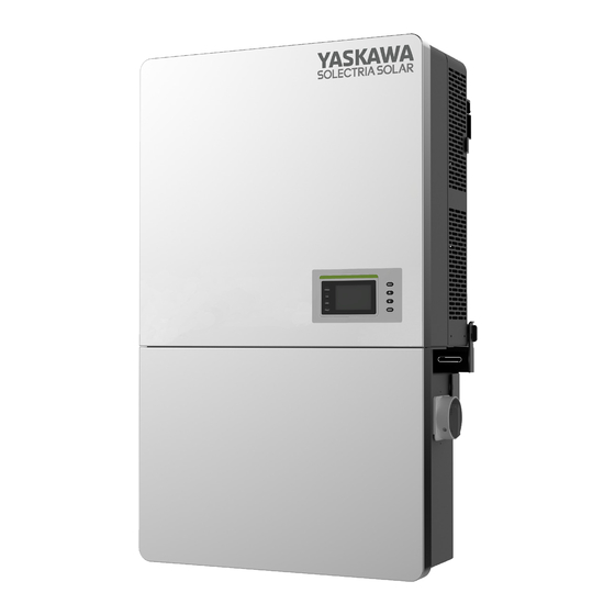
1.5 Appearance Description Figure 1.3 - Sketch of PVI 50-60TL Inverter Main Items of the Inverter: 1) Main inverter section 2) Wiring box of the inverter 3) Mounting bracket 4) External cooling fans 5) LED indication lights 6) LCD 7) Key buttons 8) DC switch: DC power on/off 9) AC switch: AC power on/off (right side of the wiring box when facing the inverter) -
Page 13: Dc Ground Fault Protection
these small variations will have negligible effects on system voltage and frequency. However, in an islanded condition the small amount of reactive power changes will force the system voltage or frequency to change significantly, which will trigger the inverter to shut down. This function is always on and cannot be turned off by the user. -
Page 14: Recommendations Before Installation
Upon which inverter is hung and Mounting bracket mounted onto a wall User manual Installation and operation manual Accessory kit Contains all necessary accessories The (5) Accessory kit contains items listed below, in Table 2.2: Table 2.2 – Accessory Kit Components Item Note M8 Expansion tubes... -
Page 15: Mechanical Installation
connect to the grid. Installation personnel must be qualified electricians or have received professional training. Sufficient space according to Figure 2.3 should be provided to allow the inverter cooling system to operate normally. Install the inverter away from flammable and explosive substances. Avoid installing the inverter in locations that exceed the temperature limits specified in the inverter data sheet to limit undesirable power loss. - Page 16 2) Installation Method (see Figure 2.2): Make sure that the mounting structure (wall, rack, etc.) is suitable to support the inverter weight. Follow the mounting guidelines below: (a) If the location permits, install the inverter vertically. (b) If the inverter cannot be mounted vertically, it may be tilted backward to horizontal.
- Page 17 NOTICE: The spacing between two adjacently mounted inverters should be ≥500mm (19.7 in.). Ensure that the air space around the inverter is well ventilated. L'espace entre deux onduleurs montés adjacentes devrait être 500mm (19,7 pouces). Veiller à ce que l'espace d'air autour de l'onduleur est bien aéré.
- Page 18 Figure 2.4 - Inverter Pillar Mounting Specifications INSTRUCTION: If the inverter is installed on Unistrut or the array racking (instead of solid wall), the space from the bottom of one inverter to the top of the inverter below may be as small as 4in. (100mm). DOCR-070645-A Page 18 of 104...
- Page 19 4) Mounting the Inverter onto the Bracket (1) Mark the 8 holes on the bearing surface for mounting the bracket as shown in Figure 2.5; 4.5” Figure 2.5 - Holes on the Bearing Surface Dimensions (2) Drill holes at the marked positions with a 10mm (0.4in.) drill and put the M8 expansion tubes ①...
- Page 20 Figure 2.6 - Securing the Mounting Bracket (3) Hang the inverter onto the mounting bracket as shown in Figure 2.7 and Figure 2.8; Lift mounting: Take out the lifting eye nut M10 (2pcs) from the accessory kit, and screw them onto the studs at the top of the inverter. Use a sling rope or bar (inserted through both lifting eye nuts) to lift the inverter onto the bracket.
- Page 21 Figure 2.7 - Mounting the Main Inverter Section on the Bracket Figure 2.8 - Grab Handle Position (4) Installing the wiring box ① Remove the cover plate at the bottom of the main section. (see Figure 2.9) Tool: No.2 Phillips head screwdriver DOCR-070645-A Page 21 of 104...
- Page 22 Figure 2.9 – Main Section Cover Plate ② Remove the cover at the top of the wiring box (see Figure 2.10) Figure 2.10 - Wiring Box Cover ③ Connect the wiring box to the main section, using M6x18 screws (4pcs) to secure the wiring box.
- Page 23 Figure 2.11 - Wiring Box Installation CAUTION: The total weight of the PVI 50-60TL inverter is 156 pounds (71kg). Please ensure the mounting is properly installed before hanging the inverter on the bracket. Le poids total de la PVI 50-60TL onduleur est d'environ 71 kg (156 livres).Veuillez vous assurer que le support est correctement installé...
- Page 24 Figure 2.12 - Secure the Main Section and Wiring Box to the Bracket (6) Optional - Install an anti-theft padlock when the installation is complete. The anti-theft padlock is used to help prevent the inverter from being stolen when the equipment is installed outdoors. The inverter may be locked on the bracket, as shown in Figure 2.13: Figure 2.13 - Anti-Theft Padlock Location DOCR-070645-A...
- Page 25 The anti-theft padlock should meet the requirement of the dimensions shown in Figure 2.14: Recommended lock size: A: Ф3~6mm B: 20~50mm C: 20~50mm Figure 2.14 - Dimensions of Anti-Theft Padlock (7) Attach the cover board as shown in Figure 2-10 to the left side of the wiring box.
- Page 26 5) Removing/Replacing the Wiring Box Cover: (1) Use a #3 Phillips screwdriver to remove the 4 screws on the wiring box and pull cover straight off the box. Do not twist or slide the cover while removing. (see Figure 2.16) Figure 2.16 –...
-
Page 27: Electrical Installation
2.3 Electrical Installation The connection interface of the PVI 50-60TL inverter: Figure 2.17 - Full View of Wiring Box with Options 20.5in(520mm) 19.0in(483mm) 17.5in(445mm) 13.2in(336mm) 10.2in(258mm) 7.1in (180mm) DC INPUT COMM. PORT DC INPUT DC INPUT AC OUTPUT For more details please see the user manual. WARNING: High touch current . - Page 28 Figure 2.19 - Internal Connection Points 1. DC input cable area: 3 x 1.5in. conduit knockouts with an additional plate provided for custom drilled conduit entrances (i.e. use if 2in., 2.5in., 3in. conduit required). NOTE: Do not enlarge the provided 1.5in. conduit knockouts. 2.
-
Page 29: Dc Connection
DC and AC GROUND Even though the inverter operates with an ungrounded PV array, the PV system still requires equipment grounding. Figure 2.20 - Equipment Grounding Locations 2.3.1 DC Connection 1) Working Mode The PVI 50-60TL inverters have three PV input sections: DC Input-1, DC Input-2 and DC Input-3. - Page 30 2) DC Fuse Configuration Table 2.4 - DC Input Power Specification (Independent mode – PVI 50-60TL per zone - DEFAULT) PVI 50TL PVI 60TL Rated DC power 17.5kW (32A) 20.5kW (38A) Max DC power allowed 25kW 30kW Absolute Max open...
- Page 31 customers’ responsibility to source and install these extra fuses. WARNING: Use of different fuses or wrongly sized fuses can cause damage to equipment or create un-safe working conditions. Any damage resulting from incompatible fuses is not covered by warranty. 3) DC Conductors Connections To ensure the optimum performance of the inverter, please read the following guidelines before making DC connections: (a) Confirm the DC configuration referring to Table 2.5 and ensure that the...
- Page 32 1/1/0 Up to #2 50 in-lbs Bypass terminals 1/0/0 Up to #2 50 in-lbs Bypass terminals *Note that the provided fuse is 15A, your string combination may require a larger rated fuse. Always verify the I rating of the input prior to connecting to the fuse holder.
- Page 33 conduits into the wiring box. (f) Connect the DC cables to the fuse holders and fasten the screws, as shown in Figure 2.21: Note: If you are using the fuse bypass- skip this step Tools: #2 Phillips bit and a Torque driver. Torque value: 3.4N-m (30 in-lbs) NOTE: If the installer does not use a torque driver to secure the conductors there is risk of potential damage to the equipment, which is not covered by...
- Page 34 Figure 2.22- DC Input Cable Connection ① Remove the 4 screws on the wiring box and take off the adaptor plate (refer to Fig.2.22). ② Using a knockout punch tool create the appropriate hole on the adaptor plate. Note that for your convenience there are guidelines for a 2”, 2.25” and 3” hole. ③...
-
Page 35: Ac And Ground Connections
NOTE: Always try connecting an equal number of wires to PV1, PV2 and PV3 for individual MPPT zone operation. NOTE: Connecting all of the inputs at zone “PV1” will result in only utilizing 33% of the inverter power WARNING: Strings must be balanced for optimum performance and AC output. When doing DC/AC ratio sizing, perform calculations at the zone level. - Page 36 Figure 2.24 - Remove the Wiring Box Cover Table 2.7 - Required Tools Tools #3 Phillips screwdriver 1/4” flat head bit 1/8” flat head bit Torque driver Diagonal pliers Wire stripping pliers Crimping pliers Table 2.8 - Torque Values AC output terminal block 132 in-lbs (15 N.m.) Internal grounding bar 35 in-lbs (4 N.m.)
- Page 37 Figure 2.25 - AC Output and Ground Cable Connections (1) Connect the AC (L1, L2, L3, N) cables to the terminal block and connect the ground cable to the internal grounding bar inside the wiring box. (See the first diagram in Figure 2.25) (2) Connect the AC (L1, L2, L3, N) cables to the terminal block and use the OT type terminal to connect the ground cable to the external grounding point at the bottom of...
- Page 38 Table 2.9 - Breaker Values Inverter AC breaker rated current A PVI 50TL PVI 60TL NOTE: If you are using aluminum wires you need to follow the following steps to prep each cable prior to connecting to the AC terminal block:...
- Page 39 continue later- you need to scrape it again. It takes 30-60 seconds for an oxidized layer to form on top of the conductors. Acceptable transformer configurations: Table 2.10 – Transformer configurations Inverter Description Configuration Compatibility 4 Wire WYE (3 phase + Neutral +GND) Compatible Note that there are...
-
Page 40: Inverter Communication Connections
2.4 Inverter Communication Connections The PVI 50-60TL inverters support industry standard Modbus RS-485 communications. 1. Communication board overview Figure 2.28 - Communication Board 2. Connectors and communication card Table 2.11 - Communication Connections and Configuration Switches Item Picture Configuration Description 1. - Page 41 4 -----RS485+ 5 -----COM 4. Selector switch for setting the 120Ω 1-----Disable the termination terminal resistor of the resistance RS-485 communication 2-----Enable the terminal resistor Figure 2.29 - Communication Connections 1- Cable connection of RS485 communication: 5 pin connector 2- Cable connection of RS485 network communication: 5 pin connector DOCR-070645-A Page 41 of 104...
-
Page 42: Third Party Monitoring Systems Modbus Connections
32 inverters/devices on the RS-485 daisy chain. The Inverter Modbus IDs are configurable from 1 to 128. Yaskawa - Solectria Solar recommends that the RS-485 daisy chain for PVI 50-60TL inverters is limited to a maximum length of 3000 ft. (914m). - Page 43 Star or T Modbus (RS-485) network topologies should always be avoided. See Figure 2.31. Figure 2.31: Connecting External DAS Modbus (RS-485) Network to the PVI 50-60TL Inverter It is important to daisy chain the inverter RS-485 connections to minimize noise and bus reflections.
- Page 44 WARNING: Risk of Electric Shock. Make sure all DC and AC power to the unit has been disconnected before opening the inverter wiring box and ensure that hazardous high voltage and power inside the equipment has been discharged. Wait at least 5 minutes before opening the wiring box.
-
Page 45: Overview Of The Ethernet Card
2.4.1 Overview of the Ethernet Card Internet 485 Port Ethernet Port RS485 terminal USB port Restore port Figure 2-33 Ethernet Card gure 2-3 Table 2.12 – Overview of Ethernet card 12 Ov Item Configuration description and Function USB port Firmware upgrade via USB disk 1.RS485+ 2. -
Page 46: Preparing The Inverter For Modbus Communications
Selector switch for setting the 120Ω terminal resistor S3 Switch of the Third part Data logger RS485 communication. Selector switch for setting the 120Ω terminal resistor S4 Switch of the RS485 communication between the inverters. Press the button over 5s, and the inverter will be Restore button restored to the factory setting. -
Page 47: Installing The Ethernet Network Card
2.4.2 Installing the Ethernet Network Card 2.4.2 Connecting the Ethernet Network Card to other inverters. 2.4.2 Preparing the Ethernet Network Card DOCR-070645-A Page 47 of 104... -
Page 48: Connecting Revenue Grade Meter
2.4.3 Connecting Revenue Grade Meter WARNING: Risk of Electric Shock. Make sure all DC and AC power has been disconnected before starting any work. Some installations require Revenue Grade Metering (RGM) for accurate energy production tracking and reporting. For that purpose the RGM needs to be connected to the SolrenView Logger over Modbus (RS-485) connection as described below. - Page 49 Choose a unique Modbus ID (address) different from any Inverter Modbus ID and set the switches for that ID as shown in Figure 2.45. Only Modbus IDs 1 through 32 can be used. Figure 2.35 - Veris RGM meter Modbus ID (address) settings. DOCR-070645-A Page 49 of 104...
- Page 50 Connect the voltage leads to the phase conductors at a location that is not normally turned off. Connect voltage leads on the Line side of the conductor to ensure constant power to the RGM. For a 3-phase system, connect the red lead to phase A, black to phase B, and yellow to phase C.
- Page 51 Snap the CT onto the conductor. Connect CTs to the correspondingly colored voltage leads. If the application can exceed 20 times the rated CT current, use wire ties to secure the I-bar to the CT housing. This CT automatically detects phase reversal, so CT load orientation is not important.
-
Page 52: Dry Contact Communication
2.4.4. Dry Contact Communication The inverter features an alarm function that opens or closes a dry contact on the communications board, which is available both as a normally open (N.O.) contact and a normally closed (N.C.) contact, as shown below: N.O. - Page 53 (or L (or L Line circuit Breaker( 3 A) Line circuit Breaker( 3 A) N.C. N.C. Fault N.O. N.O. N.C. N.C. In operation N.O. N.O. N.C. N.C. In operation N.O. N.O. Light on in trouble free operational Light on in error Figure 2.39 - Dry Contact Communication Schematic Diagram If you connect the contact port to the power distribution grid, you must install an individual miniature circuit-breaker between the dry contact and the power...
- Page 54 Tool: Wire stripping pliers Figure 2.40 - Wire Stripping Table 2.15 Cable Set-Up Position Description Value Cable type Double-layer insulated cable Outer diameter 4.5 mm~ 6 mm Cross-section area of conductor 0.2 mm² ~ 0.75 mm² Length of stripped outer wire skin Maximum 15mm Length of stripped inner wire skin Maximum 7 mm...
- Page 55 e.) Plug the cable terminal into the P8 connector. Figure 2.42 – 3-pin RS485 Communication Cable Connection 2 42 – 3-pin RS DOCR-070645-A Page 55 of 104...
-
Page 56: Commissioning
3.0: Commissioning WARNING: Please follow the guidelines below before on-grid operation to eliminate possible dangers and to ensure safety. Veuillez suivre les directives ci-dessous avant l'opération on-grid pour éliminer les dangers possibles pour assurer la sécurité. 3.1 Commissioning Checklist 3.1.1 Mechanical Installation Make sure that the mounting bracket is secure and all the screws have been tightened to the specified torque values. - Page 57 When the inverter completes “sys checking”, the LCD shows the screen as Figure 3.2 below. Press ENTER to the standard selection interface, as shown in Figure 3.2. The default grid standard is IEEE 1547. If a different standard is needed please go to “Menu Functions”...
- Page 58 8.) Time Setting: The date and time can be set as in Figure 3.3: Figure 3-3 Time Setting 9.) When the LCD screen shows the normal operation status (Figure 3.4) and the “RUN” light on the LED panel lights up, it indicates that the grid connection and power generation are successful.
-
Page 59: User Interface
4.0: User Interface 4.1 Description of LCD The inverter’s LCD mainly consists of LCD, LED indicator lights, buzzer and 4 keys, as shown in Figure 4.1. POWER GRID FAULT Figure 4.1 - LCD Interpretation for the indicator lights is shown in Table 4.1 and function of the keys is shown in Table 4.2. -
Page 60: Operation State
Light Indicates a Fault Fault Slow Indicates Alarm (light on 0.5s, light off flash status FAULT indication Fast Protective action (light on 0.5s, light off light flash 0.5s) Light No fault or power supply not working Table 4.2 - Definition of the Keys Description Definition of function Escape key... -
Page 61: Interface Types
Users can perform the corresponding operations with the 4 function keys according to the indications of the LCD. (1) The LCD interface starts with the company logo once the system is energized, as shown in Figure 4.2. Yaskawa Solectria Solar Initialization Figure 4.2 - Logo Screen (2) Indication of inverter operation mode: Figure 4.3 –... -
Page 62: Menu Functions
daily generated power and time information under normal operation. The fault information of the most recent / currently present fault will be shown on the LCD when the inverter is in fault mode. 4.4 Menu Functions LCD displays “Main user interface” when the inverter is in operation mode. Press ESC in this interface to escape the default interface and to enter the main operation interface. - Page 63 PV Information Independent PV Input Mode PdcTotal(kW) Vdc(V) Idc(A) P1/4 AC Output L1-N L3-N L2-N V(V) I(A) Main Menu F(Hz) Measurement Data Pac(Kw) Setting P Ref 100.0% Power On/Off PF Ref 1.000 History Record P2/4 Device Information Energy E-Today(kWh) E-Month(kWh) E-Total(kWh) P3/4 Others...
-
Page 64: Setting
4.4.2 Setting Move the cursor to “Settings” in the main interface. Press ENT, you will be asked for a password. Enter the password: “1111”as shown Figure 4.7. Change the password digits by pressing . Then press ENT to input the next digit and Press ENT to confirm the password or Press ESC return back to setting. -
Page 65: System Parameters
4.4.2.1 System Parameters (1) “Language Setting” One language, i.e. English is available in “Language” menu. (2) “Grid Rule”: There are four grid standards. Selecting the corresponding grid standard and press ENT confirm the selection as shown in Figure 4-9. Grid Connection Rule IEEE1547 IEEE1547 Rule-21... - Page 66 automatically if alarm or protection faults occur. This function will not respond when the inverter is in operation mode and a “FaultOperated” alarm interface is indicated. (2) “Factory Default” menu: The manufacturer’s default parameters value can be restored when the inverter is not in operation mode. If you try to change the parameters while the unit is operational “Fault Operated”...
-
Page 67: Protect Parameters
4.4.2.3 Protect Parameters In this interface you can change the Protect parameters of grid voltage, frequency and recovery, etc., as shown in Figure 4-10. But you can’t enable/disable the function. The protect parameters are shown in Table 4.10. Grid Over Voltage Protection Grid Low Voltage Protection 110.00% 88.00%... - Page 68 Table 4.3 Protection Parameters (IEEE1547) REMARK: Please contact Applications Engineering if you need to change any of the voltage settings. Grid Over Voltage Protection Setup range (lower limit, Parameter name Description default & upper limit) Threshold value of Level 1 Max. {100.00%, 110.00%, GridVoltMax1 grid voltage...
- Page 69 Protection threshold value of GridFrqMin2 {54, 57, 60} Level 2 Min. grid frequency Trip time of Level 2 Min. grid FrqMinTripT2(s) {0, 0.16, 655} frequency Protection threshold value of GridFrqMin3 {54, 57, 60} Level 3 Min. grid frequency Trip time of Level 3 Min. grid FrqMinTripT3(s) {0, 0.16, 655} frequency...
-
Page 70: L/Hvrt Parameters
Setup range (lower limit, Parameter name Description default & upper limit) Threshold value of grid voltage GridVolBalance (0.01%,10%,10%) unbalance 4.4.2.4 L/HVRT Parameters “L/HVRT” is for setting the Low Voltage Ride-Through (LVRT) and High Voltage Ride-Through (HVRT) parameters. Move the cursor to this item, and press ENT to set the parameters. - Page 71 Figure 4.13 HVRT graph Table 4.4 LVRT and HVRT parameters LVRT Setup range (lower limit, Parameter name Description default & upper limit) Threshold value of Low voltage ride {0%, 0%, 100%} LVRTVolt (1,2) through(first or second point) {0%, 0%, 100%} Time of Level Low voltage ride {0, 0, 655} LVRTTime(1,2)
- Page 72 Time of Level high voltage ride {0, 0.8, 655} HVRTTime (3,4) through(third or fourth point) {0, 12.5, 655} Threshold value of high voltage ride {100%, 115%, 135%} HVRTVolt (5,6) through(fifth or sixth point) {100%, 115%, 135%} Time of Level high voltage ride {0, 12.5, 655} HVRTTime(5,6) through(fifth or sixth point))
-
Page 73: Active Derating Setting
4.4.2.5 Active Derating Setting “Active Derating Setting” menu is to set the active power derating parameters include active power derating, over frequency derating, low frequency derating and high temperature frequency derating, etc. The parameters are shown in Table 4.5. Power vs Friquency 60.4 OvrFrqMin(Hz) OvrFrqMax(Hz) -
Page 74: Reactive Derating Setting
Recovery time of grid over voltage OvrVoltFilterT(s) {1,60,90} derating Grid Over Frequency Derating Setup range (lower limit, Parameter name Description default & upper limit) Min Threshold value of grid over OvrFrqMin(Hz) {60,60.4,72} Frequencyderatingstarted Max Threshold value of grid over OvrFrqMax(Hz) {60,61.4,72} Frequencyderating over Slop of grid over... - Page 75 (PFCurveP1,PFCurvePF1) Inductive (P%) Capacitive (PFCurveP2,PFCurvePF2) Figure 4-15 PF(P) Curve Mode (3) Q(U) Curve Q(U) curve mode Note: The reactive compensation changes according to the grid voltage change, as shown in Figure 4.16. INSTRUCTION: The Q(U) curve function is only available for IEEE-1547 grid standards. Q(%) (QuCurveU2i,QuCurveQ2i) Inductive...
-
Page 76: Arc Parameters
PFSetValue {-1,1,1} Figure 4-14 PFCurveP1 {0,0.5,1} Figure 4-14 PFCurvepF1 {-1,1,1} Figure 4-14 PFCurveP2 {0,1,1} Figure 4-14 PFCurvepF2 {-1,-0.9,1} Figure 4-14 PFCurveTriVol(V) {480,480,528} PF curve trip voltage PF curve revocation PFCurveUndoVol(V) {432,441.6,480} voltage QuCurveU1(V) {480,518.4,528} Figure 4-15 QuCurveQ1 {-1,0,1} Figure 4-15 Figure 4-15 QuCurveU2(V) {518.4,528,528}... -
Page 77: Other Parameters
ARC Bandwith Setting ARC Bandwith Setting Bandwidth1 Bandwidth2 StartFrq1 StartFrq2 Proportion1 Proportion2 Filter1 Filter2 Setting Threshold1(dB) Threshold2(dB) System Parameters SigPerApdLimit1(dB) Control Command SigPerApdLimit2(dB) Protection Parameters LVRT/HVRT Setup P1/4 P2/4 Power Derating Setup ARC Percentage Setting ARC Others Parameters Reactive Power Derating Setup PctStartFrq1 TestPeriod ARCParaGro... -
Page 78: Power On/Off
4.4.3 Power ON/OFF Manual power ON/OFF is required after parameter change, after getting an error message or updating the software. The unit will automatically go into the OFF state. Press ESC or ENT to enter into the Main Menu, then press ENT and go to the submenu “Power On/OFF”. -
Page 79: Device Information
4.4.5 Device Information Move the cursor from the main operation interface “Main Menu” Press ENT and go to sub menu “Device Information” and press ENT to check the device information as shown in Figure 4-20. Inverter information Device Model: SCA60KTL-DO/US- PVI-50/60TL Device SN: 0 0000 0000 0000 DSP Ver:... -
Page 80: Operation
5.0: Operation 5.1 Start-Up Manual Start-up: Manual start-up is required after regulation setting change or manual (fault) shut-down. Move the cursor from the main operation interface to “Setting”. Press ENT and go to submenu “1 ON/OFF”. Then move the cursor to “ON” and press ENT to start the inverter. - Page 81 Figure 5.2 - Default Indication Interface for Normal Operation In this mode, the inverter converts the power generated by PV modules to AC continuously and feeds into the power grid. (3) Standby mode, as shown in Figure 5.3: The inverter will enter standby mode when the output voltage and power of PV modules do not meet the startup conditions or PV voltage and input power are lower than the set values.
-
Page 82: Grid-Tied Power Generation
Current Error Date Time Error 2015/10/22 12:20:08 ArcboardErr 2015/10/22 12:20:08 Fault0040 Fault0040 2015/10/22 12:20:08 Fault0040 2015/10/22 12:20:08 Fault0040 2015/10/22 12:20:08 P1/1 Figure 5.4 - Fault Indication Interface WARNING: All installation and wiring connections should be performed by qualified technical personnel. Disconnect the inverter from PV modules and the AC supply before performing maintenance. -
Page 83: Maintenance And Uninstallation Of Inverter
6.0: Maintenance and Uninstallation of inverter 6.1 Fault Shutdown and Troubleshooting 6.1.1 LED Fault and Troubleshooting When contacting Solectria for support please provide the serial number of the inverter and the fault message. If the fault is regarding a voltage issue, please measure the AC and DC voltage at the inverter prior to calling. - Page 84 Table 6.2 - LCD Troubleshooting Table Definition: Prompt detection of abnormal temperature Possible causes: 1.Temperature sensor is reading -25C; 2.Temperature Sensor socket connecter has poor 1.TempSensorErr contact; 2.Temperature Sensor is damaged; Recommended solutions: 1.Observe temperature display; 2.Switch off 3-phase working power supply and then reboot the system;...
- Page 85 4.Contact after-sales service personnel Definition: Internal alarm Possible causes: Internal memory has a problem 4.EepromErr Recommended solutions: 1.Observe for 5 minutes and see whether the alarm will be eliminated automatically; 2. The inverter is still producing power normally 3.Contact after-sales service personnel Definition: Ambient or internal temperature is too high >70C Possible causes:...
- Page 86 4.Check whether the cable between the inverter and power grid is disconnected or has any fault; 5.Contact after-sales service personnel Definition: Grid voltage frequency is abnormal, or power grid is not detected Possible causes: 1.Grid frequency is abnormal; 2.Cable connection between the inverter and the grid is poor;...
- Page 87 to environmental factor; 2.Grounding is abnormal; 3. Internal inverter fault Recommended solutions: 1.Observe for 10 minutes and see whether the alarm will be eliminated automatically; 2.Detect whether the electrical connection is abnormal 3.Contact after-sales service personnel Definition: Insulation impedance of PV positive to ground or PV negative to ground exceeds the specified range Possible causes: Air humidity is high...
-
Page 88: Product Maintenance
Recommended solutions: 1.Observe for 10 minutes and see whether the alarm will be eliminated automatically; 2.Contact after-sales service personnel Definition: Internal fault of the inverter Possible causes: Fault IntFault0010~0150 Fault occurs inside the inverter Recommended solutions: 1.The inverter can be forced to restart once if it is required by operation and if it is confirmed that there is no other problem;... -
Page 89: Clean The Air Vent Filter
2.) Check for cable damage, especially whether the cable surface is scratched or smooth. Repair or replace the cables if necessary. 6.2.2 Clean the Air Vent Filter The inverter can become hot during normal operation. It uses built in cooling fans to provide sufficient air flow to help in heat dissipation. -
Page 90: Replace The Inverter
50~60mm Figure 6.1 - Replace Cooling Fans 6.2.4 Replace the Inverter Please confirm the following before replacing the inverter: (1) The inverter is turned off. (2) The DC switch of the inverter is turned to OFF position. Afterwards replace the inverter according to the following steps: a.) Unlock the padlock if it is installed on the inverter. - Page 91 b.) Use a No. 2 Phillips or No. 10 wrench head screwdriver to unscrew the 2 screws on both sides of the inverter. Figure 6.3 - Remove the Screws on Both Sides c.) Use a No. 10 Hex wrench to remove the 4 screws between the main section and the wiring box.
- Page 92 Figure 6.4 - Disconnect the Main Section from the Wiring Box d.) Use a No.2 Phillips head screwdriver to remove the 2 screws on the left side of the wiring box, and take off the cover board. Put the board on the connector of wiring box.
-
Page 93: Uninstalling The Inverter
6.3 Uninstalling the Inverter Uninstall the inverter according to the following steps when the service is due or for other reasons: DANGER: Please disconnect the electrical connection in strict accordance with the following steps. Otherwise, the inverter will be damaged and the service personnel’s life will be endangered. -
Page 94: Technical Data
7.0: Technical Data Model Name PVI 50TL PVI 60TL DC Input Max. PV Power 75kW (25kW/MPPT) 90kW (30kW/MPPT) Nominal DC Input Power 51.5kW 61.5kW Max. DC Input Voltage 1000Vdc Operating DC Input 200-950Vdc Voltage Range Start-up DC Input Voltage 330V/80W... - Page 95 Max. Efficiency 99.0% CEC Efficiency 98.5% Stand-by / Night <30W / <2W Consumption Environment Protection Degree TYPE 4X Cooling Variable speed cooling fans Operating Temperature -22°F to +140°F / -30°C to +60°C (derating from +122°F Range / +50°C) Operating Humidity 0-95%, non-condensing Operating Altitude 13123.4ft / 4000m (derating from 9842.5ft / 3000m)
- Page 96 Figure 7.1 - PVI 60TL Derating Curve of PV Input Voltage 110% 100% 0.8%/V 100 200 300 400 500 600 850 950 1000 PV Voltage (V) Figure 7.2 - PVI 50TL Derating Curve of PV Input Voltage DOCR-070645-A Page 96 of 104...
- Page 97 NOTE 2: When the ambient temperature is higher than 113°F (45°C), the output power may begin derating. For DC voltage as shown in Figure 7.3: Output power Celsius Figure 7.3 - PVI 50-60TL Derating Curve with High Temperature DOCR-070645-A Page 97 of 104...
- Page 98 NOTE 3: When the altitude is higher than 9843ft (3000m), the power of the inverter will start derating, as shown in Figure 7.3: Po/Pn Pin/Pn 100% -30%/km 3000 4000 Altitude(m) Figure 7.4 - PVI 50-60TL Derating Curve with High Altitude NOTE 4: The inverter can output the AC power with full loads within 100%~110% of the rated grid voltage.
-
Page 99: Accessory Options
PVI 50-60TL Installation and Operation Manual PVI Series Inverters 8.0: Accessory Options The PVI 50-60TL comes with several options that allow the inverter to support a wide range of real life applications. Fuse Bypass OPT-FUSEBYPASS-PVI-50-60TL allows customers to combine the DC inputs outside of the inverter and enter with only one or two combined inputs. -
Page 100: Shade Cover
PVI 50-60TL Installation and Operation Manual PVI Series Inverters Shade Cover OPT-SHADECOVER-PVI-50-60TL is specifically designed for inverters mounted at a 15-degree tilt angle. It protects the inverter from harsh weather and direct sunlight/extremely hot temperatures while reducing thermal gain on the inverter and increasing energy production. - Page 101 PVI 50-60TL Installation and Operation Manual PVI Series Inverters Figure 8.4 –Shade Cover Installation; Steps 1 and 2 DOCR-070645-A Page 101 of 104...
- Page 102 PVI 50-60TL Installation and Operation Manual PVI Series Inverters Install top bracket as shown. Nuts M10- 2 pcs. Torque to 50 in-lbs (5.6 N.m). Install bottom bracket as shown. Screws M6x16- 4 pcs. Torque to 25 in-lbs (2.8 N.m). Figure 8.4 –Shade Cover Installation; Steps 3 and 4 DOCR-070645-A Page 102 of 104...
-
Page 103: Appendixa - Pvi 50-60Tl Datasheet
PVI 50-60TL Installation and Operation Manual PVI Series Inverters Appendix A – PVI 50-60TL Datasheet https://solectria.com/support/documentation/inverter-datasheets/pvi-50tl-pvi-60tl- transformerless-3-ph-string-inverters-datasheet/ Appendix B – String Sizing Tool http://solectria.com/support/string-sizing-tool/ Appendix C – Contact Information Yaskawa – Solectria Solar 360 Merrimack Street Lawrence, Massachusetts 01843 Tel: 978.683.9700 Fax: 978.683.9702 Sales Support: inverters@solectria.com... -
Page 104: Appendixe - Ul 1741 / Ul 1699B/ Ieee 1547 / Csa 22.2#107.1
PVI 50-60TL Installation and Operation Manual PVI Series Inverters Appendix E – UL 1741 / UL 1699B/ IEEE 1547 / CSA 22.2#107.1 DOCR-070645-A Page 104 of 104...
Need help?
Do you have a question about the PVI 50TL and is the answer not in the manual?
Questions and answers