Sungrow SG80KTL Quick Installation Manual
Hide thumbs
Also See for SG80KTL:
- User manual (103 pages) ,
- User manual (103 pages) ,
- Installation manual (6 pages)
Advertisement
Quick Links
Download this manual
See also:
User Manual
SG80KTL Quick Installation Guide
This guide provides a general instruction of the installation procedures of SG80KTL.
In no case shall this guide substitute for the user manual or related notes on the
device.
Make sure to read over, fully understand and strictly follow the detailed
instructions of the user manual and other related regulations before installing
the equipment.
Any violation could result in personal death or injury or device damage.
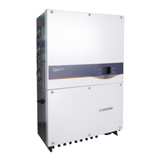
1 Unpacking and Inspection
Step 1
Remove the backplate and
fasteners from the packaging.
Step 2
Inspect the inverter for visible
damages
completeness of the delivery
contents according to the
inner packing list.
Contact your supplier if any of the contents is missing. SG80KTL is
unavailable if any damage is detected.
and
check
the
1110mm
1
Advertisement

Related Manuals for Sungrow SG80KTL


Summary of Contents for Sungrow SG80KTL
-
Page 1: Unpacking And Inspection
SG80KTL Quick Installation Guide This guide provides a general instruction of the installation procedures of SG80KTL. In no case shall this guide substitute for the user manual or related notes on the device. Make sure to read over, fully understand and strictly follow the detailed instructions of the user manual and other related regulations before installing the equipment. - Page 2 ×18 Fig. 1-1 Scope of delivery Item Name Description Inverter Backplate Used to fix the inverter to the installation site. Quality certificate, packing list, test report, CD and quick Documents user manual Fasten set Six units to fasten backplate to metal frame. Two M4×16 screws to fix the inverter with the Fix screw backplate.
- Page 3 2 Mounting Inverter onto the metal frame Select the installation location and regulate the clearances of multiple inverters, referring to the user manual. Move the inverter to the installation site with the help of another person or the lifting device by means of the handles.
- Page 4 Secure the backplate to the metal frame firmly by the supplied fastener. Step 5 Torque of the fasten nut is 35 Nm. Name Description Hexagon nut Spring washer Flat washer Screw bolt M10*45 Metal frame Backplate Step 6 Lift the inverter above the backplate and then slide down to make sure they match perfectly.
-
Page 5: Electrical Connection
3 Electrical Connection Death hazards due to high voltage existing inside the inverter! Make sure that all the DC and AC cables to the inverter are not live before you start the electrical work. Do not turn on the AC side or DC side circuit breaker until all inverter electrical connections have completed. - Page 6 3-2 Cables Selection AC Cable Description Remark Protective layer External diameter of the cable: 30.5-50 mm Length of insulation to be 24 mm stripped off Insulation layer Range: 30-150mm ; recommended value: 70 Cross section of AC cables * The external diameter of the AC cable described in A is proper range. ...
- Page 7 Shielded twisted pair cables or Shielded twisted pair Ethernet cables.
- Page 8 3-3 AC Connection High voltage inside the inverter! Ensure all cables are voltage-free before electrical connection. Do not connect the AC circuit breaker until all inverter electrical connections are completed. Disconnect the AC circuit breaker and ensure it will not reconnect Step 1 accidentally.
- Page 9 follow two tables. Screw tightening torque(Nm) Cable section(mm 26.7~42.3 13.6 53.5~67.4 11.9 16.3 70~107 15.8 22.6 127~177 19.8 29.4 The table values are used for the following cable type: 1. Copper stranded(including sector); 2. aluminum solid(including sector); Screw tightening torque(Nm) Cable section(mm 26.7~42.3 10.8...
- Page 10 If the cross-section of the AC cable is sectorial, please place the apex(A) of sector upside and then fix the AC cable to the corresponding terminals.. A( apex ) 90° Observe the AC terminal layout. Device will not work normally if the phase cable is connected to the PE terminal.
- Page 11 Step 3 Lead the cable through the cable Positive Insulator gland. Crimp Contact Insert the crimp contact into the Step 4 Cable Gland insulator until it snaps into place. Then pull gently to make sure it is secured. Screw the cable gland to insulator Step 5 Negative Insulator with tightening torque 2.5…3 Nm.
- Page 12 • Check the positive and negative polarity of the PV cells. After confirmation, you can insert the DC connectors into the input terminals on the bottom of the inverter. • For the same MPPT, reverse connection of a single string is prohibited.
- Page 13 The ground connection of this second PE terminal cannot replace the connection of the PE terminal of the AC cables. Make sure the two PE terminals are all grounded reliably. Sungrow shall hold no liability for any possible consequences caused by ignorance of this warning.
-
Page 14: Completing Installation
Configuration circuitboard RM48 interface COM NC NO COM NC NO RS485 RS485 Fault Alarm Emergency Stop For RJ45 Connection the pins definitions are shown below.In Ethernet cable, Pin 3 white-green cable defines RS485- B while Pin 6 green cable defines RS485+ A. RJ45 Port Corresponding Relationship Between Cables and Pins:... -
Page 15: Button Operation
4 Commissioning Before starting SG80KTL, make sure all installation and connections are completed and verified. Close the AC circuit breaker. Step 1 Step 2 Rotate DC switch to “ON” position. Step 3 Suppose there are sufficient sunlight and enough DC power. PV arrays initialize and supply DC power to inverter. - Page 16 After setting the Country parameter, please proceed to set other parameters of the inverter in accordance with the specific requirements of the local grid. Before commissioning, please check thoroughly if the set parameters meet the local grid requirement. Refer to “Protection Parameter Setting” in User Manual for country code explanation. If the inverter is installed where the country code is not included, please choose item “Other”...
- Page 17 If the country code set as Other, a Grid codes page as Other Grid codes shown in the right will appear. Press to select grid code and press ENTER to confirm. 50Hz 60Hz If the country selected is not the abvementioned 5 countries, enter the next step directly.
- Page 18 Step 11 Inverter will enter into startup process. Observe the status of LED indicators and the P(%) P-ac 60.000 LCD main screen. If commissioning succeeds, E-day 15.6 the “RUN” indicator will be on and “Run” will E-tot 497600 be displayed on the “State” area. State 8 11 14 2015/01/31 10:30...
Need help?
Do you have a question about the SG80KTL and is the answer not in the manual?
Questions and answers