National Instruments FieldPoint FP-1000 User Manual
Network modules
Hide thumbs
Also See for FieldPoint FP-1000:
- User manual (50 pages) ,
- Quick start manual (24 pages) ,
- Operating instructions manual (12 pages)

Related Manuals for National Instruments FieldPoint FP-1000


Summary of Contents for National Instruments FieldPoint FP-1000
- Page 1 ™ FieldPoint FP-1000/1001 User Manual FieldPoint FP-1000/1001 User Manual August 1998 Edition Part Number 321631B-01 © Copyright 1997, 1998 National Instruments Corporation. All rights reserved.
- Page 2 Netherlands 0348 433466, Norway 32 84 84 00, Singapore 2265886, Spain 91 640 0085, Sweden 08 730 49 70, Switzerland 056 200 51 51, Taiwan 02 377 1200, United Kingdom 01635 523545 National Instruments Corporate Headquarters 6504 Bridge Point Parkway Austin, Texas 78730-5039 USA Tel: 512 794 0100...
- Page 3 90 days from date of shipment, as evidenced by receipts or other documentation. National Instruments will, at its option, repair or replace software media that do not execute programming instructions if National Instruments receives notice of such defects during the warranty period.
-
Page 4: Table Of Contents
Connecting the FP-1001 to the Serial Network ............2-8 RS-485 Interface Specifications ..............2-10 RS-485 Network Termination and Biasing ............ 2-10 Configuring the FP-1000/1001 ..................2-12 Setting the Network Address................2-13 Setting the Baud Rate ..................2-15 © National Instruments Corporation FieldPoint FP-1000/1001 User Manual... - Page 5 Using the FieldPoint Lookout Driver Class ..............4-13 Using the FieldPoint LabVIEW VIs................4-16 Using the FieldPoint LabWindows/CVI Functions............4-18 Using the FieldPoint OPC Server................. 4-19 Using FieldPoint with an Optomux Server ..............4-21 FieldPoint FP-1000/1001 User Manual © National Instruments Corporation...
- Page 6 ToolTips Showing the Name of an Item..........4-6 Figure 4-3. ScreenTips Showing a Description of an Item ........4-7 Figure 4-4. Communication Resource Configuration Window........ 4-8 Figure 4-5. Channel Configuration Dialog Box ............4-10 © National Instruments Corporation FieldPoint FP-1000/1001 User Manual...
- Page 7 Network Address Switch Settings for the FP-1000/1001 ..... 2-14 Table 2-2. Baud Rate Switch Settings for the FP-1000/1001......... 2-15 Table 3-1. Module Configuration Results After HotPnP Replacement....3-6 Table 3-2. STATUS LED Flashes and Corresponding Error Conditions....3-8 FieldPoint FP-1000/1001 User Manual viii © National Instruments Corporation...
-
Page 8: About This Manual
About This Manual This manual describes how to install and use the FieldPoint FP-1000 and FP-1001 network modules. How to Use This Manual Set Operating Instructions for Modules and Bases Installation FieldPoint Server Specifications Online Help FieldPoint Programmer FieldPoint Network Connection,... -
Page 9: Organization Of This Manual
FP-1000 and FP-1001 network modules. Customer Communication, contains forms you can • Appendix B, use to request help from National Instruments or to comment on our products and manuals. • Glossary contains an alphabetical list and description of terms used in this manual, including abbreviations, acronyms, metric prefixes, mnemonics, and symbols. -
Page 10: Related Documentation
FieldPoint Server online help Customer Communication National Instruments wants to receive your comments on our products and manuals. We are interested in the applications you develop with our products, and we want to help if you have problems with them. To make it easy for you to contact us, this manual contains comment and configuration forms for you to complete. -
Page 11: Fp-1000/1001 Network Module Overview
Local Bus Status Status Connector Connector Switch Switch LEDs LEDs Cover Cover RS-485 RS-485 RS-232 Connector Connector Connector Rail Clip Rail Clip Power Power Connector Connector Figure 1-1. FP-1000 and FP-1001 Network Modules © National Instruments Corporation FieldPoint FP-1000/1001 User Manual... - Page 12 FP-1001 does not provide a separate RS-485 repeater. You can network multiple FP-1001 modules in multidrop fashion. The FP-1001 communicates over RS-485, utilizing full-duplex mode. It is optically isolated, which prevents fault coupling between the RS-485 network and the FP-1001. FieldPoint FP-1000/1001 User Manual © National Instruments Corporation...
-
Page 13: Hardware Installation And Configuration
Hook the lip on the rear of the network module onto the top of a 35 mm DIN rail and press the network module down onto the DIN rail as shown in Figure 2-2. © National Instruments Corporation FieldPoint FP-1000/1001 User Manual... -
Page 14: Figure 2-2. Installing The Fp-1000/1001 Network Module Onto A Din Rail
Figure 2-3. Locking the FP-1000/1001 Network Module onto a DIN Rail After the network module is installed, connect the terminal base to the network module as explained in the next section, Connecting Terminal Bases with DIN Rail Mounting. FieldPoint FP-1000/1001 User Manual © National Instruments Corporation... -
Page 15: Connecting Terminal Bases With Din Rail Mounting
5. Place the protective cover onto the last terminal base on the bank, as shown in Figure 2-4. Local Bus Connectors Firmly Mated Protective Cover Rail Clip Locked Rail Figure 2-4. Connecting Terminal Bases © National Instruments Corporation FieldPoint FP-1000/1001 User Manual... -
Page 16: Removing The Fp-1000/1001 From The Din Rail
Local Bus Connector Network Module Rail Clip Rail Clip Unlocked Rail Clip Locked Figure 2-5. FieldPoint Network Module Snap the panel mount accessory onto the module as shown in Figure 2-6. FieldPoint FP-1000/1001 User Manual © National Instruments Corporation... -
Page 17: Connecting Terminal Bases With Panel Mounting
2. Drill pilot holes in the panel to mount the terminal bases. A drilling guide is provided with the network module panel mount accessory. 3. Attach the terminal base to the network module by firmly mating the local bus connectors. © National Instruments Corporation FieldPoint FP-1000/1001 User Manual... -
Page 18: Removing The Fp-1000/1001 And Terminal Bases From The Panel
Press firmly to seat the module on the terminal base. The terminal base latch locks the I/O module into place when the module is firmly seated. To connect additional I/O modules, repeat the procedure to install them onto additional terminal bases. FieldPoint FP-1000/1001 User Manual © National Instruments Corporation... -
Page 19: Connecting The Fp-1000 To Your Computer
24) FP-1001 network modules to the RS-485 repeater port of the FP-1000. This network configuration is shown in Figure 2-8. Host Computer FP-1001 FP-1001 FP-1000 RS-485 RS-232 Figure 2-8. Host Computer Connected to One FP-1000 and Two FP-1001 Network Modules © National Instruments Corporation FieldPoint FP-1000/1001 User Manual... -
Page 20: Rs-232 Interface Specifications
One option for connecting the FP-1001 is to connect it to the RS-485 repeater port of an FP-1000 as shown in Figure 2-8. The RS-485 port on the FP-1001 must be wired in 4-wire, full duplex mode when connected to the RS-485 repeater port. FieldPoint FP-1000/1001 User Manual © National Instruments Corporation... -
Page 21: Figure 2-10. Host Computer Connected To Three Fp-1001 Network Modules
An alternative method is to connect the FP-1001 directly to your host computer, if your host computer provides an RS-485 interface. Contact National Instruments for information about available RS-485 hardware. You can connect up to 25 FP-1001 network modules to each RS-485 port on the host computer. -
Page 22: Figure 2-11. Rs-485 Connector Pinout For The Fp-1000 And Fp-1001
To install them, twist the resistor leads with the RS-485 signal wires and then insert them into the RS-485 Combicon adapter as shown in Figure 2-12. The 120 Ω resistor in the figure is a terminating resistor. FieldPoint FP-1000/1001 User Manual 2-10 © National Instruments Corporation... -
Page 23: Figure 2-12. Terminating Rs-485 Using The Combicon Adapter
RX inputs of the FP-1001 to the TX outputs of the FP-1000. Figure 2-13. Typical Signal Connections for Host Computer Connected to One FP-1000 and Multiple FP-1001 Network Modules © National Instruments Corporation 2-11 FieldPoint FP-1000/1001 User Manual... -
Page 24: Configuring The Fp-1000/1001
1 2 3 4 5 6 7 8 Baud Address Rate 1 2 3 4 5 6 7 8 Switch Cover (Removed) Figure 2-15. Address and Baud Rate Switch FieldPoint FP-1000/1001 User Manual 2-12 © National Instruments Corporation... -
Page 25: Setting The Network Address
Table 2-1 shows the possible switch positions and the corresponding address of the FieldPoint network module. © National Instruments Corporation 2-13 FieldPoint FP-1000/1001 User Manual... - Page 26 1 2 3 4 5 6 7 8 1 2 3 4 5 6 7 8 1 2 3 4 5 6 7 8 Other Settings Not Allowed 1 2 3 4 5 6 7 8 FieldPoint FP-1000/1001 User Manual 2-14 © National Instruments Corporation...
-
Page 27: Setting The Baud Rate
The network module filters and regulates this supplied power and provides power for all the I/O modules in the bank. Therefore you need not provide power separately to each FieldPoint I/O module in the bank. © National Instruments Corporation 2-15 FieldPoint FP-1000/1001 User Manual... -
Page 28: Calculating Power For A Fieldpoint Bank
I/O modules. It does not include any power consumed by devices that you wire to the terminal bases. The operating instructions for each FieldPoint I/O module contain power consumption information. FieldPoint FP-1000/1001 User Manual 2-16 © National Instruments Corporation... -
Page 29: Completed Hardware Installation
If the STATUS LED is blinking, refer to Table 3-2, STATUS LED Flashes and Corresponding Error Conditions, in Chapter 3, Feature Set Description. © National Instruments Corporation 2-17 FieldPoint FP-1000/1001 User Manual... -
Page 30: Feature Set Description
FieldPoint Explorer software or the FieldPoint command set. • Watchdog data value for each channel • Watchdog data enable/disable status for each channel • Watchdog enabled/disabled status for each I/O module • Watchdog timeout value for the bank © National Instruments Corporation FieldPoint FP-1000/1001 User Manual... -
Page 31: Snapshot Feature
If you have enabled the SnapShot feature, the FP-1000/1001 restores the stored settings to all I/O modules and channels in the bank every time you power up, until you disable the SnapShot feature. If the FieldPoint FP-1000/1001 User Manual © National Instruments Corporation... -
Page 32: Programmable Power-Up State
SnapShot information. If you subsequently enable the SnapShot feature, you can ensure that your system powers up with the configuration and output levels that you specified when storing the Programmable Power-Up States. © National Instruments Corporation FieldPoint FP-1000/1001 User Manual... -
Page 33: Hotpnp (Hot Plug And Play)
When you insert an I/O module with the power on, it is automatically recognized, configured, and made available on the network. The following sections describe how the HotPnP feature works under different conditions. FieldPoint FP-1000/1001 User Manual © National Instruments Corporation... -
Page 34: Hotpnp During Power-Up
I/O module is missing, and may continue to send commands to the missing I/O module. Each command returns an error response, but the FP-1000/1001 remembers the commands sent to the missing I/O module. © National Instruments Corporation FieldPoint FP-1000/1001 User Manual... - Page 35 SnapShot information While one or more replacement I/O modules in the bank are being serviced by the HotPnP feature, the other I/O modules in the bank FieldPoint FP-1000/1001 User Manual © National Instruments Corporation...
-
Page 36: Power-On Self Test (Post)
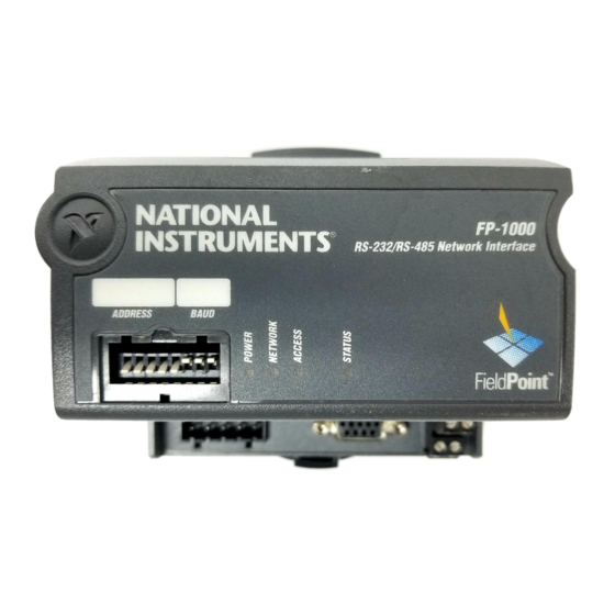
LED Indicators, for more information. LED Indicators The FP-1000/1001 has four LED indicators: POWER, NETWORK, ACCESS, and STATUS. Figure 3-1 shows the LEDs on the FP-1000/1001. ADDRESS BAUD ADDRESS BAUD Figure 3-1. LEDs on the FP-1000/1001 © National Instruments Corporation FieldPoint FP-1000/1001 User Manual... - Page 37 Verify that the protective cover is on the local bus connector of the last terminal base and that none of the pins of that connector are touching or bent. FieldPoint FP-1000/1001 User Manual © National Instruments Corporation...
- Page 38 The network module was unable to locate an I/O module waiting to be configured. Verify that there are no more than nine terminal bases in the bank, and that no terminal bases were added to the bank while power was applied. © National Instruments Corporation FieldPoint FP-1000/1001 User Manual...
-
Page 39: Installing And Using The Fieldpoint Software
• LabWindows/CVI Functions • OPC Server You can download future versions of FieldPoint software from the National Instruments FTP site at ftp.natinst.com/support/ fieldpoint/Server FieldPoint Explorer Configuration Utility FieldPoint Explorer is the configuration utility for FieldPoint hardware and software. You can use FieldPoint Explorer to accomplish the following tasks: •... -
Page 40: Bridgeview Server
C function calls to communicate with I/O items configured in the FieldPoint Explorer. An instrument driver with a set of function panels and example programs is provided to accelerate your development process. FieldPoint FP-1000/1001 User Manual © National Instruments Corporation... -
Page 41: Opc Server
FieldPoint Explorer to configure the FieldPoint devices before running your software. For more information on using FieldPoint with Optomux servers, refer to the Using FieldPoint with an Optomux Server section, later in this chapter. © National Instruments Corporation FieldPoint FP-1000/1001 User Manual... -
Page 42: Data Throughput With The Fieldpoint Servers
Explorer you define I/O items (which represent one or more physical I/O channels) that you want to write to or read from. FieldPoint Explorer also provides a user interface from which you can interactively FieldPoint FP-1000/1001 User Manual © National Instruments Corporation... -
Page 43: Getting Assistance While You Work
ToolTips, ScreenTips, and online help. ToolTips identify tool bar icons and most items on the screen. Rest your pointer over the element you are interested in, and its name appears, as shown in Figure 4-2. © National Instruments Corporation FieldPoint FP-1000/1001 User Manual... -
Page 44: Figure 4-2. Tooltips Showing The Name Of An Item
ScreenTips by clicking the question mark button in the title bar of the dialog box and then clicking the item you want to know more about. The ScreenTip appears as shown in Figure 4-3. FieldPoint FP-1000/1001 User Manual © National Instruments Corporation... -
Page 45: Getting Started With Fieldpoint Explorer
FieldPoint Explorer to launch the FieldPoint Explorer program. 3. Add a communications resource to the Device Network Hierarchy. To add the resource, first click on the + sign next to IA Server with © National Instruments Corporation FieldPoint FP-1000/1001 User Manual... -
Page 46: Figure 4-4. Communication Resource Configuration Window
Also FieldPoint FP-1000/1001 User Manual © National Instruments Corporation... - Page 47 Continue this for each channel in the Channel Number list that you want to configure. g. Click the OK button when you are finished. h. Click the Yes button when asked if you want to write these settings to the device. © National Instruments Corporation FieldPoint FP-1000/1001 User Manual...
-
Page 48: Figure 4-5. Channel Configuration Dialog Box
10. You can also write to output channels of I/O Items that you have configured. Select a device in the DNH window with output channels. FieldPoint FP-1000/1001 User Manual 4-10 © National Instruments Corporation... - Page 49 13. Exit the FieldPoint Explorer application. Note: You must exit FieldPoint Explorer before you can communicate with the FieldPoint system using one of the methods described in the subsequent sections. © National Instruments Corporation 4-11 FieldPoint FP-1000/1001 User Manual...
-
Page 50: Using The Fieldpoint Bridgeview Server
BridgeVIEW’s initial tile screen. 5. Click on the Configuration Wizard button in the lower-right corner of the Tag Configuration Editor window, and then select FieldPoint from the list of servers that appears. FieldPoint FP-1000/1001 User Manual 4-12 © National Instruments Corporation... -
Page 51: Using The Fieldpoint Lookout Driver Class
2. Exit FieldPoint Explorer. Note: You must exit FieldPoint Explorer before you can use the FieldPoint driver class from Lookout. 3. Start Lookout, and create a new control panel or open an existing one. © National Instruments Corporation 4-13 FieldPoint FP-1000/1001 User Manual... - Page 52 Browse button to find the configuration file you saved.) Make any changes you want to make to the poll rate or other parameters, and click on the OK button. FieldPoint FP-1000/1001 User Manual 4-14 © National Instruments Corporation...
- Page 53 FieldPoint Explorer. The Eng. units in the scaling window indicate the configured range of analog I/O Items. From this window, you can modify the alias, alarm conditions, and other parameters of each data member in the FieldPoint object. © National Instruments Corporation 4-15 FieldPoint FP-1000/1001 User Manual...
-
Page 54: Using The Fieldpoint Labview Vis
Installing and Using the FieldPoint Software For more information about the FieldPoint driver object class and data members, refer to the National Instruments FieldPoint section of Chapter 18, Object Class Reference, in your Lookout Reference Manual. Using the FieldPoint LabVIEW VIs When you install the FieldPoint software, a library of FieldPoint VIs is created if LabVIEW has already been installed on your computer. - Page 55 This example reads the value of an I/O Item value from the FieldPoint device. To write to an Output Item, use FP Write instead of FP Advise (or FP Read). Figure 4-8. LabVIEW Diagram for LabVIEW Example Application © National Instruments Corporation 4-17 FieldPoint FP-1000/1001 User Manual...
-
Page 56: Using The Fieldpoint Labwindows/Cvi Functions
) files to support the different compiler compatibility .obj modes that LabWindows/CVI supports (Microsoft Visual C/C++, Borland, Watcom, and Symantec). When FieldPoint software is installed, the Microsoft compatibility mode is installed by default. To use an alternate FieldPoint FP-1000/1001 User Manual 4-18 © National Instruments Corporation... -
Page 57: Using The Fieldpoint Opc Server
FieldPoint OPC server, you should do so. 2. Create a group. Groups are a collection of I/O items. Some OPC clients may not give you the option of creating groups, or they may be created for you. © National Instruments Corporation 4-19 FieldPoint FP-1000/1001 User Manual... - Page 58 Some OPC clients that do not support this “GetErrorString” method may still provide a way for you to manually look up the FieldPoint message corresponding to the error code using the method. FieldPoint FP-1000/1001 User Manual 4-20 © National Instruments Corporation...
-
Page 59: Using Fieldpoint With An Optomux Server
0 and its maximum value represented by 4095. In some cases Optomux data may be represented by integers from 4096 (representing the minimum value of an analog channel) to 8191 (representing the maximum value of an analog channel). © National Instruments Corporation 4-21 FieldPoint FP-1000/1001 User Manual... - Page 60 Programmer Reference Manual to get the most out of your FieldPoint hardware. Examples of programs that directly access the serial port to communicate with the FieldPoint network modules are available on the National Instruments FTP site at ftp.natinst.com/support/fieldpoint/Examples/ FieldPoint FP-1000/1001 User Manual 4-22 ©...
-
Page 61: Appendix A Specifications
Specifications sections in Chapter 2, Hardware Installation and Configuration. Power Supply Range ......11 to 30 VDC Power Consumption ......1 watt + 1.15 * ∑(I/O Module Consumption) Maximum Terminal Bases per Bank ...9 © National Instruments Corporation FieldPoint FP-1000/1001 User Manual... - Page 62 Operating Temperature....... –40° to +70° C Storage Temperature ......–55° to +90° C Relative Humidity ......5% to 90% noncondensing Compliance Electrical Safety ......... designed to meet IEC 1010 EMI Emissions/Immunity....CISPR 11 FieldPoint FP-1000/1001 User Manual © National Instruments Corporation...
-
Page 63: Appendix B Customer Communication
Electronic Services Bulletin Board Support National Instruments has BBS and FTP sites dedicated for 24-hour support with a collection of files and documents to answer most common customer questions. From these sites, you can also download the latest instrument drivers, updates, and example programs. For recorded instructions on how to use the bulletin board and FTP services and for BBS automated information, call 512 795 6990. - Page 64 Telephone and Fax Support National Instruments has branch offices all over the world. Use the list below to find the technical support number for your country. If there is no National Instruments office in your country, contact the source from which you purchased your software to obtain support.
- Page 65 Clock speed ______MHz RAM _____MB Display adapter __________________________ Mouse ___yes ___no Mouse type _________________________________________________ National Instruments application software product ______________________ Version _________ Other application software product ___________________________________ Version ________ National Instruments server _________________________________________ Version ________ Other installed software that may use serial ports _______________________________________...
- Page 66 FieldPoint Banks Please use one page per FieldPoint bank. Network module _____________________________________ Firmware revision ____________ Address __________________________________________ Baud rate ___________________ Circle the state of the following items when your problem occurs: LEDs POWER: ON/OFF NETWORK: ON/OFF ACCESS: ON/OFF STATUS: ON/OFF SnapShot feature Enabled/Disabled Watchdog timer Enabled/Disabled Timeout value _______ ms...
- Page 67 National Instruments for technical support helps our applications engineers answer your questions more efficiently. If you are using any National Instruments hardware or software products related to this problem, include the configuration forms from their user manuals. Include additional pages if necessary.
- Page 68 Documentation Comment Form National Instruments encourages you to comment on the documentation supplied with our products. This information helps us provide quality products to meet your needs. Title: ™ FieldPoint FP-1000 /1001 User Manual Edition Date: August 1998 Part Number: 321631B-01 Please comment on the completeness, clarity, and organization of the manual.
-
Page 69: Glossary
The combination of one FieldPoint network module and one or more terminal bases and I/O modules. bits per second celsius CISPR International Special Committee On Radio Interference Data Set Ready electronic data sheet electromagnetic interference electrostatic discharge © National Instruments Corporation FieldPoint FP-1000/1001 User Manual... - Page 70 Hot Plug and Play hertz International Electrotechnical Commission inches input/output Light-emitting diode OLE for Process Control POST power-on self test random-access memory Request to Send Volts Volts direct current Vrms Volts root mean squared FieldPoint FP-1000/1001 User Manual © National Instruments Corporation...
- Page 71 2-12 to 2-15 how to use manual set, ix baud rate settings, 2-15 organization of manual, x network address settings, 2-13 to 2-14 related documentation, xi configuration, saving for FieldPoint bank, 3-2 to 3-4 © National Instruments Corporation FieldPoint FP-1000/1001 User Manual...
- Page 72 2-15 to 2-16 LabWindows/CVI functions, 4-2 to 4-3, removing network module 4-18 to 4-19 from DIN rail, 2-4 Lookout driver class, 4-2, 4-13 to 4-16 from panel, 2-6 OPC server, 4-3, 4-19 to 4-20 FieldPoint FP-1000/1001 User Manual © National Instruments Corporation...
- Page 73 See FieldPoint network interface specifications, 2-10 modules. isolation from FieldPoint system network termination and biasing, RS-485 (note), 2-9 to 2-10 ports, 2-10 to 2-12 network watchdog timer, 3-1 to 3-2 © National Instruments Corporation FieldPoint FP-1000/1001 User Manual...
- Page 74 DIN rail mounting, 2-3 with panel mounting, 2-5 to 2-6 termination and biasing, RS-485 ports, 2-10 to 2-12 throughput, 4-3 update rate. See throughput. watchdog timer, 3-1 to 3-2 FieldPoint FP-1000/1001 User Manual © National Instruments Corporation...
Need help?
Do you have a question about the FieldPoint FP-1000 and is the answer not in the manual?
Questions and answers