Table of Contents
Advertisement
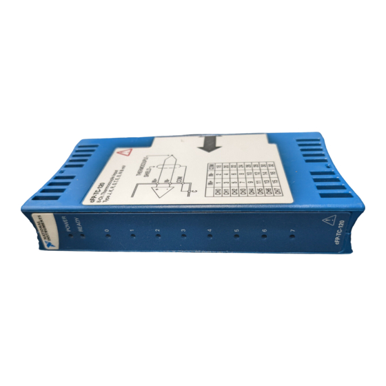
FieldPoint Operating Instructions
FP-TC-120
8-Channel Thermocouple Input Modules
These operating instructions describe how to install and use the
National Instruments FP-TC-120 and cFP-TC-120 thermocouple
input modules (referred to inclusively as the [c]FP-TC-120). For
details on configuring and accessing the [c]FP-TC-120 over a
network, refer to the user manual for the FieldPoint network
module you are using.
Features
The [c]FP-TC-120 is a FieldPoint thermocouple input module with
the following features:
•
Eight thermocouple or millivolt inputs
•
Built-in linearization and cold-junction compensation for eight
thermocouple types: J, K, R, S, T, N, E, and B
Four voltage ranges: ±25, ±50, ±100, and –20 to 80 mV
•
•
Open-thermocouple detection and indicator LEDs
•
16-bit resolution
•
Differential inputs
•
Filtering against 50 and 60 Hz noise
•
2,300 V
rms
inter-module communication bus and the I/O channels
•
250 V
rms
•
–40 to 70 °C operation
•
Hot plug-and-play
FieldPoint™, National Instruments™, NI™, and ni.com™ are trademarks of National Instruments Corporation.
Product and company names mentioned herein are trademarks or trade names of their respective companies.
For patents covering National Instruments products, refer to the appropriate location: Help»Patents in your software,
the patents.txt file on your CD, or ni.com/patents .
373344A-01
© 2002 National Instruments Corp. All rights reserved.
AND C
transient overvoltage protection between the
isolation voltage rating
October 2002
FP-TC-120
Advertisement
Table of Contents

Related Manuals for National Instruments CFP-TC-120


Summary of Contents for National Instruments CFP-TC-120
- Page 1 FieldPoint™, National Instruments™, NI™, and ni.com™ are trademarks of National Instruments Corporation. Product and company names mentioned herein are trademarks or trade names of their respective companies. For patents covering National Instruments products, refer to the appropriate location: Help»Patents in your software, the patents.txt file on your CD, or ni.com/patents .
-
Page 2: Installing The Fp-Tc-120
The cFP-TC-120 receives operating power from the backplane. To install the cFP-TC-120, refer to Figure 2 and follow these steps: 1. Align the captive screws on the cFP-TC-120 with the holes on the backplane. The alignment keys on the cFP-TC-120 prevent backward insertion. -
Page 3: Wiring The [C]Fp-Tc-120
2. Press firmly to seat the cFP-TC-120 on the backplane. 3. Using a number 2 Phillips screwdriver with a shank of at least 64 mm (2.5 in.) length, tighten the captive screws to 1.1 N ⋅ m (10 lb ⋅ in.) of torque. The nylon coating on the screws prevents them from loosening. -
Page 4: Taking Measurements With The [C]Fp-Tc-120
IN(–), and a pull-up resistor on the positive terminal, IN(+), to detect open thermocouples. Each channel has a COM terminal that connects to the isolated ground reference. Each channel is filtered, then sampled by a 16-bit analog-to-digital FP-TC-120 and cFP-TC-120 ni.com... -
Page 5: Connecting Voltage Input Signals
–20 to 80 mV. An input signal outside the selected input range causes the [c]FP-TC-120 to report an error for the Out of range affected channel. The [c]FP-TC-120 ignores any configuration of thermocouple type when you select one of these ranges. © National Instruments Corp. FP-TC-120 and cFP-TC-120... -
Page 6: Connecting Thermocouple Input Signals
NIST-175 standard for thermocouple characteristics, based on the ITS-90 International Temperature Scale. These linearization algorithms are typically accurate to within ±0.05 °C (0.03 °F) of the NIST standard over the entire range of temperatures defined by the NIST for the supported thermocouple types. FP-TC-120 and cFP-TC-120 ni.com... -
Page 7: Detecting Open Thermocouples
For optimal cold-junction compensation, NI recommends that you use the FP-TB-3 isothermal terminal base with the FP-TC-120 and the cFP-CB-3 isothermal connector block with the cFP-TC-120. © National Instruments Corp. FP-TC-120 and cFP-TC-120... -
Page 8: Determining Measurement Accuracy And Minimizing Errors
If you are using an external terminal block or a cable backshell to connect to the cFP-TC-120, you can compensate for cold junctions by connecting a thermistor between pins 36 and 37. You must use a thermistor with a resistance of 5 kΩ at 25 °C. Refer to the... - Page 9 Figure 6. Type R and S Errors Max Over Temp Max at Room Temp Typ Over Temp Typ at Room Temp –300 1200 1500 1800 Measured Temperature (°C) Figure 7. Type J, K, N, T, and E Errors © National Instruments Corp. FP-TC-120 and cFP-TC-120...
-
Page 10: Cold-Junction Temperature Measurement Accuracy
Isothermal Terminal Base The FP-TB-3 is designed with isothermal construction to keep the terminals at the same temperature. NI recommends that you use the FP-TB-3 to ensure the best accuracy of thermocouple measurements. Adjacent FieldPoint modules (either network FP-TC-120 and cFP-TC-120 ni.com... - Page 11 FP-TB-3. Hot or cold air draft can be another source of thermal gradients. However, circulating air around nearby components may help them dissipate heat and reduce thermal gradients on the terminal base. © National Instruments Corp. FP-TC-120 and cFP-TC-120...
-
Page 12: Status Indicators
In addition to the green POWER and READY indicators, the [c]FP-TC-120 has eight red open-thermocouple LEDs labeled . When a channel that has been configured for temperature measurements detects an open thermocouple, the red LED for that channel lights. FP-TC-120 and cFP-TC-120 ni.com... -
Page 13: Upgrading The Fieldpoint Firmware
Working voltage is defined as the signal voltage plus the common-mode voltage. Common-mode voltage is the voltage of the module with respect to ground. © National Instruments Corp. FP-TC-120 and cFP-TC-120... - Page 14 Operate the [c]FP-TC-120 at or below Installation Category II. Installation Category II is for measurements performed on circuits directly connected to the low-voltage installation. This category refers to local-level distribution, such as that provided by a standard wall outlet. FP-TC-120 and cFP-TC-120 ni.com...
-
Page 15: Specifications
Cold-junction accuracy..... 0.15 °C typ, 0.3 °C max There is typically an additional 0.2 °C difference between the temperature of the cold-junction sensor and that of the actual terminals. Update rate........Each channel is updated every 1.13 s © National Instruments Corp. FP-TC-120 and cFP-TC-120... - Page 16 POWER and READY; eight red LEDs for open thermocouple detected Weight FP-TC-120........140 g (4.8 oz.) cFP-TC-120........ 130 g (3.7 oz.) Power Requirements Power from network module .... 350 mW Isolation Voltage Isolation voltage rating ..... 250 V , Installation Category II Channel-to-channel isolation ....
- Page 17 Maximum altitude......2,000 m Pollution degree ....... 2 Shock and Vibration Operating shock (IEC 68-2-27) cFP-TC-120 ........50 g, 3 ms half sine, 3 shocks; 30 g, 11 ms half sine, 3 shocks Operating vibration, random (IEC 60068-2-34) FP-TC-120........10–500 Hz, 2.2 g cFP-TC-120........
-
Page 18: Where To Go For Support
Figure 10 shows the mechanical dimensions of the FP-TC-120 installed on a terminal base. Dimensions are given in millimeters [inches]. If you are using the cFP-TC-120, refer to the Compact FieldPoint controller user manual for the dimensions and cabling clearance requirements of the Compact FieldPoint system. - Page 19 Singapore 65 6 226 5886, Slovenia 3 425 4200, South Africa 11 805 8197, Spain 91 640 0085, Sweden 08 587 895 00, Switzerland 056 200 51 51, Taiwan 02 2528 7227, United Kingdom 01635 523545 © National Instruments Corp. FP-TC-120 and cFP-TC-120...
Need help?
Do you have a question about the CFP-TC-120 and is the answer not in the manual?
Questions and answers