Table of Contents
Advertisement
Advertisement
Table of Contents

Related Manuals for Wasp WWS650


Summary of Contents for Wasp WWS650
- Page 1 Wasp WWS650 2D Wireless Scanner Quick Reference Guide...
- Page 2 Wasp Technologies logo are registered trademarks of Wasp Technologies Barcode Technologies in many countries, including the U.S.A. and the E.U. Duraline is a trademark of Wasp Barcode Technologies registered in many countries, including the U.S.A. and the E.U. All other brand and product names may be trade- marks of their respective owners.
-
Page 3: Table Of Contents
Replacing the Battery Pack ..........9 Using the Wasp WWS650 ............10 Linking the Reader ..............11 Link Wasp RF Devices to Base ....... 11 Linking to a Bluetooth Adapter in Serial Port Profile Mode................11 Linking to a Bluetooth Adapter in HID mode..12 Variable PIN Code ............ - Page 4 Wasp Technologies Limited Factory Warranty ....38 Warranty Coverage ..........38 Warranty Exclusions..........39 No Assignment ............39 Risk of Loss .............. 40 Ergonomic Recommendations ..........41 Cleaning ..................41 Support through the Website .......... 42 Hex-Numeric Keypad ..............43 For HID Variable Pin Code only.......
- Page 5 1.1 Wasp grants to End User, a personal, non-exclusive, non-transferable, non- sublicensable, revocable, limited license to use the Software, solely on the Wasp Product in which it is embedded or for which it is intended for use, in machine-readable form only, solely for End User's internal business purposes.
- Page 6 52.227-19 or in the Rights in Technical Data and Computer Software clause at DFARS 252.227-7013(c)(1)(ii), whichever is applicable. 8.2 If End User is using the Wasp Product outside of the United States, End User must comply with the applicable local laws of the country in which the Wasp Product is used and with U.S.
- Page 7 End User obtained the license to govern, interpret, and enforce all of End User' s and Wasp' s respective rights, duties, and obligations arising from, or relating in any manner to, the subject matter of this Agree- ment, without regard to conflict of law principles.
-
Page 8: Software Product Policy
- END - Software Product Policy Wasp reserves the right to ship its products with the lat- est version of software/firmware available. This provides our customers with the very latest in Wasp software technology. -
Page 9: Description
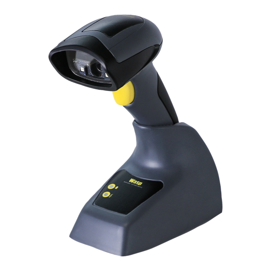
Wasp WWS650 Description With rich feature sets and extensive options, the WWS650 product series from Wasp represents the premium level of data collection equipment for general purpose applications. The Wasp WWS650 readers have enhanced optics with improved motion tolerance allowing codes placed on fast... -
Page 10: Setting Up The Reader
Reader and Base, in case of inad- vertent movements. Lock Lever To Lock the Reader in the Base Insert the Reader into the Base. The lock lever rests in its natural disengaged position toward the bot- tom of the Base. WWS650... - Page 11 Setting Up the Reader Figure 1. Lock lever disengaged Engage the locking mechanism by pushing up the lever as far as it will go. Figure 2. Lever in locked position It is good practice to put the scanner in the locked condition at the end of the working shift, or when not in use for an extended period of time.
-
Page 12: Connecting The Base Station
(if necessary) before proceeding. Connect the interface cable before applying power to the Base Station. The Wasp WWS650 reader can also be Powered by the Terminal. When powered by the Terminal, the battery charger is automatically set as Slow charge. - Page 13 Verify before connection that the reader’s cable type is compatible with your host equipment. The Wasp WWS650 reader can be set up to require a PIN code when connecting to the host. If you are adding new equipment to a system...
-
Page 14: System And Network Layout
Plug the AC Adapter into an approved AC wall socket with the cable facing downwards (as shown in Figure 3) to prevent undue strain on the socket. System and Network Layout Typical Setup with Cradle and Host Figure 5. Reader Layout Reader Host Base Station WWS650... -
Page 15: Using The Bc2030™ Radio Base
Connecting the Base Station Using the BC2030™ Radio Base Radio Base LEDs LEDs on the Wasp Base provide information about the Base as well as battery charging status, as shown in Figure Figure 6. Base LEDs Table 1. Radio Base LEDs... -
Page 16: Charging The Batteries
Micro-USB Connector Alternatively, simply insert the WWS650 into the base. When the scanner is fully seated in the cradle, it will sound a “chirp” to indicate that the cradle has detected the scanner connec- tion. -
Page 17: Replacing The Battery Pack
Connecting the Base Station Replacing the Battery Pack Before proceeding, read “Battery Safety” in the Regulatory and Safety insert. Wasp recommends annual replacement of rechargeable battery packs to ensure maximum performance. NOTE Using a coin or screwdriver, unscrew the bottom of the battery pack until it is disengaged. -
Page 18: Using The Wasp Wws650
Using the Wasp WWS650 Using the Wasp WWS650 The Wasp WWS650 normally functions by capturing and decoding codes. The aiming system is activated on trigger pull and indicates the center of the field of view which should be positioned over the bar code:... -
Page 19: Linking The Reader
Use the host computer’s Bluetooth manager to “Discover new devices” and select "Wasp Scan- ner." If you receive an error message, it may be necessary to disable security on the device. -
Page 20: Linking To A Bluetooth Adapter In Hid Mode
Bluetooth manager. Link to PC in HID The WWS650 reader can be set up to require a PIN code when connecting. If you want to set up a PIN, or when adding new equipment to a... -
Page 21: Variable Pin Code
BlueSoleil 8) require a Variable PIN Code. When attempting connection, the application presents a window that includes a PIN Code which is to be input using the WWS650. Please read the bar code "Variable PIN Code" and restart the sequence from step 2 above. Variable PIN Code... -
Page 22: Programming
Factory defaults are based on the interface type. Configure the reader for the correct inter- face before scanning this label. NOTE Standard Product Default Settings WWS650... -
Page 23: Hid Alt Mode
Programming HID Alt Mode Read the configuration command label below for the HID Alt Mode feature. ENTER/EXIT PROGRAMMING MODE HID Alt Mode = OFF HID Alt Mode = ON Power Off Scan the bar code below to shut off power to the handheld until the next trigger pull. -
Page 24: Country Mode
Keyboard Wedge for IBM AT PS2 without alternate key encoding but without external keyboard All other interfaces support ONLY the following : U.S., Belgium, Britain, France, Germany, Italy, Spain, Sweden. COUNTRY MODE ENTER/EXIT PROGRAMMING MODE Country Mode = U.S. Country Mode = Belgium Country Mode = Britain WWS650... - Page 25 Country Mode COUNTRY MODE (continued) Country Mode = Croatia* Country Mode = Czech Republic* Country Mode = Denmark* Country Mode = France Country Mode = French Canadian* Country Mode = Germany *Supports only the interfaces listed in the Country Mode feature description (Base configuration only) Quick Reference Guide...
- Page 26 Country Mode = Hungary* Country Mode = Italy Country Mode = Japanese 106-key* Country Mode = Lithuanian* Country Mode = Norway* Country Mode = Poland* *Supports only the interfaces listed in the Country Mode feature description (Base configuration only) WWS650...
- Page 27 Country Mode COUNTRY MODE (continued) Country Mode = Portugal* Country Mode = Romania* Country Mode = Spain Country Mode = Sweden Country Mode = Slovakia* Country Mode = Switzerland* *Supports only the interfaces listed in the Country Mode feature description (Base configuration only) Quick Reference Guide...
-
Page 28: Caps Lock State
It does not apply when an alternate key encoding keyboard is selected. CAPS LOCK STATE ENTER/EXIT PROGRAMMING MODE Caps Lock State = Caps Lock OFF Caps Lock State = Caps Lock ON Caps Lock State = AUTO Caps Lock Enable WWS650... -
Page 29: Selecting The Base Interface Type
Selecting the Base Interface Type Selecting the Base Interface Type Upon completing the physical connection between the base and its host, proceed directly to Interface Selection below for information and programming for the interface type the base is connected to (for example: RS-232, Keyboard Wedge, USB, etc.) and scan the appropriate bar code to select your sys- tem’s correct interface type. - Page 30 RS-232 Wincor-Nixdorf Select RS232-WN RS-232 for use with OPOS/UPOS/JavaPOS Select RS-232 OPOS USB COM to simulate RS-232 standard interface Select USB-COM-STD a. Download the correct USB COM driver from www.waspbarcode.com USB-OEM USB-OEM (can be used for OPOS/UPOS/JavaPOS) Select USB-OEM WWS650...
-
Page 31: Keyboard Interface
Selecting the Base Interface Type Keyboard Interface Use the programming bar codes to select options for USB Keyboard and Wedge Interfaces. KEYBOARD AT, PS/2 25-286, 30-286, 50, 50Z, 60, 70, 80, 90 & 95 w/ Standard Key Encoding Select KBD-AT Keyboard Wedge for IBM AT PS2 with standard key encoding but without external keyboard Select KBD-AT-NK... - Page 32 Select KBD-IBM-3153 Keyboard Wedge for IBM Terminals 31xx, 32xx, 34xx, 37xx make only keyboard Select KBD-IBM-M Keyboard Wedge for IBM Terminals 31xx, 32xx, 34xx, 37xx make break keyboard Select KBD-IBM-MB USB Keyboard with alternate key encoding Select USB Alternate Keyboard WWS650...
-
Page 33: Scancode Tables
Select KBD-DIG-VT USB Keyboard with standard key encoding Select USB Keyboard Scancode Tables Reference the WWS650 PRG for information about control character emulation which applies to keyboard interfaces. Country Mode This feature specifies the country/language supported by the keyboard when configured through the base. See "Country Mode"... -
Page 34: Numlock
As you read code symbols, adjust the distance at which you are holding the reader. Aiming System A number of options for customizing control of the Aiming System are available. See the PRG for more information and programming bar codes. WWS650... -
Page 35: Good Read Green Spot Duration
Reading Parameters Good Read Green Spot Duration Successful reading can be signaled by a good read green spot. Use the bar codes below to specify the duration of the good read pointer beam after a good read. GOOD READ GREEN SPOT DURATION ENTER/EXIT PROGRAMMING MODE Green Spot Duration = Disable (Green Spot is Off) Green Spot Duration = Short (300 msec) -
Page 36: Scan Modes
Scanning is continually on. If the trigger is pulled, the reader acts as if it is in Trigger Single Mode. Double Read Timeout prevents undesired multiple reads while in this mode. 1. See the Product Reference Guide (PRG) for more infor- mation WWS650... - Page 37 Scan Modes SCAN MODES ENTER/EXIT PROGRAMMING MODE Scan Mode = Trigger Single Scan Mode = Trigger Hold Multiple Scan Mode = Trigger Pulse Multiple Scan Mode = Flashing Scan Mode = Always On Scan Mode = Stand Mode Quick Reference Guide...
-
Page 38: Pick Mode
Pick Mode = Disable Pick Mode = Enable Multiple Labels in a Volume Enables/disables the ability of scanner to decode multiple labels in the same image. Several programming options are available for this feature, see the PRG for more information. WWS650... -
Page 39: Technical Specifications
Technical Specifications Technical Specifications The following table contains Physical and Performance Char- acteristics, User Environment and Regulatory information. Physical Characteristics Color White or Black Height 6.4”/163 mm Dimensions Length 3.6”/91 mm Width 1.6”/41 mm Approximately Weight (without 200 g (reader) cable) 230 g (base charger) Electrical Characteristics... - Page 40 PDF-417 Min Resolution = 5 mil Datamatrix Min Resolution = 7.5 mil Print Contrast 25% minimum reflectance Minimum a. 13 mils DOF based on EAN. All other 1D codes are Code 39. All labels grade A, typical environmental light, 20°C, label inclination 10° WWS650...
- Page 41 GS1 DataBar Limited; GS1 DataBar Expanded; GS1 DataBar Truncated; DATABAR Expanded Coupon. 2D / Stacked Codes The Wasp WWS650 scanner is capable of decoding the following symbologies using multiple frames (i.e. Multi-Frame Decoding): PDF-417; QR Code; Aztec; Datamatrix; Inverse Datamatrix; Data- matrix is configurable for the following parameters:;...
- Page 42 Radio Features Frequency Range 2400 to 2483.5 MHz Range (in open air) 25 m a. It is acceptable to handle this with ULE b. See "Interface Selection" on page 21 for a listing of available interface sets by version type. WWS650...
-
Page 43: Led And Beeper Indications
LED and Beeper Indications LED and Beeper Indications The reader’s beeper sounds and its LED illuminates to indi- cate various functions or errors on the reader. An optional “Green Spot” also performs useful functions. The following tables list these indications. One exception to the behaviors listed in the tables is that the reader’s functions are program- mable, and so may or may not be turned on. - Page 44 Programming exited Program- followed by ming Mode. reset beeps. Reader sounds Label Program- Cancel label has two times at low ming Mode Cancel been scanned. frequency and Item Entry current volume. WWS650...
-
Page 45: Error Codes
Error Codes Error Codes Upon startup, if the reader sounds a long tone, this means the reader has not passed its automatic Selftest and has entered FRU (Field Replaceable Unit) isolation mode. If the reader is reset, the sequence will be repeated. The following table describes the LED flashes/beep codes associated with an error found. -
Page 46: Wasp Technologies Limited Factory Warranty
Products are sold on the basis of specifications applica- ble at the time of manufacture and Wasp has no obligation to modify or update products once sold. If Wasp determines that... -
Page 47: Warranty Exclusions
Warranty Exclusions The Wasp Factory Warranty shall not apply to: any product which has been damaged, modified, altered, repaired or upgraded by other than Wasp service person- nel or its authorized representatives; (ii) any claimed defect, failure or damage which Wasp... -
Page 48: Risk Of Loss
Customer shall bear risk of loss or damage for product in transit to Wasp Technologies. Wasp Technologies shall assume risk of loss or damage for product in Wasp Technolo- gies possession. In the absence of specific written instruc- tions for the return of product to Customer, Wasp... -
Page 49: Ergonomic Recommendations
Ergonomic Recommendations Ergonomic Recommendations In order to avoid or minimize the potential risk of ergonomic injury follow the recommenda- tions below. Consult with your local Health & Safety Manager to ensure that you are adhering CAUTION to your company’s safety programs to prevent employee injury. -
Page 50: Support Through The Website
Cleaning Cleaning (continued) Support through the Website Wasp provides several services as well as technical support through its website. Log on www.waspbarcode.com and click on the SUPPORT link which gives you access to: Downloads by selecting your product model from the drop- down list in the Search by Product field for specific Data Sheets, Manuals, Software &... -
Page 51: Hex-Numeric Keypad
Hex-Numeric Keypad Hex-Numeric Keypad Use the bar codes that follow to enter numbers as you would select digits/characters from a keypad. Quick Reference Guide... - Page 52 Hex-Numeric Keypad Hex-Numeric Keypad (continued) WWS650...
-
Page 53: For Hid Variable Pin Code Only
Hex-Numeric Keypad Hex-Numeric Keypad (continued) For HID Variable Pin Code only If you make a mistake, scan the CANCEL barcode below to abort and not save the entry string. You can then restart. Cancel an incomplete HID Variable PIN Code Finish by scanning the Exit HID Variable PIN Code label. - Page 54 Hex-Numeric Keypad NOTES WWS650...
- Page 56 ©2014 - 2018 Wasp and its Group companies - All right reserved. Wasp Technologies and the Wasp Technologies logo are registered trademarks of Wasp Barcode Technologies in many countries, including the U.S.A. and the E.U. Wasp Barcode Technologies 1400 10th Street Plano, Texas...
Need help?
Do you have a question about the WWS650 and is the answer not in the manual?
Questions and answers