Siemens milltronics ILE-37 Instruction Manual
Sensing head
Hide thumbs
Also See for milltronics ILE-37:
- Application manual (8 pages) ,
- Application examples (17 pages)
Table of Contents
Advertisement
Advertisement
Table of Contents

Related Manuals for Siemens milltronics ILE-37


Summary of Contents for Siemens milltronics ILE-37
- Page 1 Instruction Manual September 2003 milltronics ILE-37...
- Page 2 Contact SMPI Technical Publications at the following address: Technical Publications Siemens Milltronics Process Instruments Inc. 1954 Technology Drive, P.O. Box 4225 Peterborough, Ontario, Canada, K9J 7B1 Email: techpubs@siemens-milltronics.com For the library of SMPI instruction manuals, visit our Web site: www.siemens-milltronics.com © Siemens Milltronics Process Instruments Inc. 2003...
-
Page 3: Table Of Contents
Table of Contents Milltronics ILE-37 Sensing Head ..................1 Specifications ........................2 Installation ........................... 4 Side Mount..............................4 Base Mount .............................. 4 Sensing Plate............................5 Viscous Damper............................5 Interconnection............................6 Non-Hazardous Unit without LVDT Conditioner Card ............6 Non-Hazardous Unit with Sensing Head Mounted LVDT Conditioner Card ....7 Non-Hazardous Unit with Remote-Located LVDT Conditioner Card .......8... -
Page 5: Milltronics Ile-37 Sensing Head
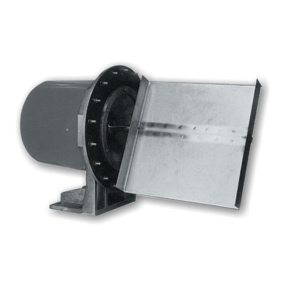
Milltronics ILE-37 Sensing Head The Milltronics ILE-37 sensing head is an out-of-process sensing element for A, E, V, and C series solids flowmeters. It is used for continuous in-line weighing of powdered or granular dry bulk solid materials. The material is directed toward the sensing plate. The horizontal impact force of the material, deflecting the sensing plate, displaces the core of the sensing head LVDT (linear variable differential transformer). -
Page 6: Specifications
• Epoxy paint, synergistic polymer, or PFA coating of external aluminum casting surfaces • Epoxy painted mild steel or stainless steel rear cover Approvals • CE • Optional CSA. Class I, Groups C and D; Class II, Groups E, F, and G Page 2 Milltronics ILE-37 – INSTRUCTION MANUAL 7ML19985CW01... - Page 7 • –40 to 50 °C (–40 to 122 °F) Input • 0 to 1.0 V AC from LVDT Output • 0 to 50 mV DC to Siemens Milltronics integrator; [maximum 300 m (1000 ft) separation between conditioner card and integrator] Approvals • CE Enclosure •...
-
Page 8: Installation
1 t/h, or if handling product temperatures above 60 °C. The side mount version is factory-installed on Siemens Milltronics flowmeters designed for side mount sensing heads. -
Page 9: Sensing Plate
The damper must be full and free of air bubbles, with the damper cover in the UP position, during flowmeter operation. filler bottle sensing head shipping screws damper cover damper (Check that there are no bubbles.) 7ML19985CW01 Milltronics ILE-37 – INSTRUCTION MANUAL Page 5... -
Page 10: Interconnection
LVDT sensing head terminal block cable clamp – – – to Integrator *For Encapsulated LVDT (hazardous) YEL = WHITE BLU = ORANGE GRN = YELLOW Note: Ground shield at Integrator only. Page 6 Milltronics ILE-37 – INSTRUCTION MANUAL 7ML19985CW01... -
Page 11: Non-Hazardous Unit With Sensing Head Mounted Lvdt Conditioner Card
Non-Hazardous Unit with Sensing Head Mounted LVDT Conditioner Card • Not applicable to Hazardous-rated units • LVDT to LVDT Conditioner Card connections are made by Siemens Milltronics LVDT Siemens Milltronics LVDT conditioner card LVDT INTEGRATOR 14 1 BLUE YELLOW BLACK... -
Page 12: Non-Hazardous Unit With Remote-Located Lvdt Conditioner Card
Run additional conductors: - from SF500 terminal 12 to conditioner terminal block marked "Integrator +EXC" - from SF500 terminal 13 to conditioner terminal block marked "Integrator –EXC" For further connection information on specific LVDTs, consult Siemens Milltronics. ♦ Note: Shields are common, but not grounded to chassis. Run cable shields through SHLD terminals and ground at Integrator only. -
Page 13: Calibration
To Integrator LVDT EXC. or LVDT increase decrease Conditioner Card Note: Ensure the new position of the LVDT core allows free movement within the LVDT bore. Use 80 grams for A-40 flowmeters. 7ML19985CW01 Milltronics ILE-37 – INSTRUCTION MANUAL Page 9... -
Page 14: Span Test
Zero and Span calibration, Span Adjust, and Factoring, should be performed. sensing changes < 0.01 V AC plate voltmeter test weight Page 10 Milltronics ILE-37 – INSTRUCTION MANUAL 7ML19985CW01... -
Page 15: Integrator Calibration
• Accurate calibration is not assured until material tests and a manual span adjustment have been performed, as outlined in the Integrator instruction manual. string fixing bolt calibration pulley string test weight 7ML19985CW01 Milltronics ILE-37 – INSTRUCTION MANUAL Page 11... -
Page 16: Maintenance And Spare Parts
Check test weight Rate display Test flowmeter linearity Remove any material buildup in the impact area of the sensing plate. Spare Parts Siemens Milltronics recommends the following spare parts be kept on hand: • sensing head inner gasket • sensing head outer gasket (base mount version only) •... -
Page 17: Range Springs
After you have removed and replaced the range spring, recalibrate the flowmeter and integrator. (See the Integrator manual, CALIBRATION section, for details.) Perform the LVDT output zero procedure. Perform an integrator zero and span calibration. Perform a span Adjust and factoring as required. 7ML19985CW01 Milltronics ILE-37 – INSTRUCTION MANUAL Page 13... -
Page 18: Troubleshooting
Troubleshooting Every Milltronics ILE-37 sensing head is subjected to extensive quality assurance procedures to ensure the highest possible degree of quality, reliability, and performance is achieved. The following listing indicates the probable cause, and proper course of action to be taken should the specified fault symptom occur. -
Page 19: Linearity
Some integrators are equipped with a linearization function to compensate for non-linear material flow patterns. Stand-alone linearizing devices are also available for this purpose. Electronic linearization should not be used to correct non-linear test weight results. 7ML19985CW01 Milltronics ILE-37 – INSTRUCTION MANUAL Page 15... - Page 25 Notes...
- Page 26 Notes...
- Page 28 Siemens Milltronics Process Instruments Inc. Siemens Milltronics Process Instruments Inc. 2003 1954Technology Drive, P .O. Box 4225 Subject to change without prior notice Peterborough, ON, Canada K9J 7B1 Rev. 1.0 Tel: (705) 745-2431 Fax: (705) 741-0466 *7ml19985CW01* Email: techpubs@siemens-milltronics.com...
Need help?
Do you have a question about the milltronics ILE-37 and is the answer not in the manual?
Questions and answers