Table of Contents
Advertisement
Available languages
Available languages
Operator's Manual
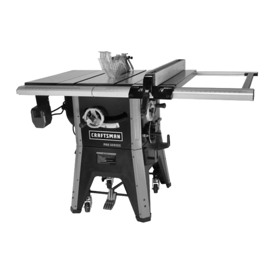
10"
CONTRACTOR TABLE SAW
Model No.
124.58833
CAUTION:
Read and follow all Safety
Rules and Operating
Instructions before First Use of
this Product. Keep this Manual
with Tool.
Sears Brands Management Corp., Hoffman Estates, IL 60179 U.S.A
www.craftsman.com
Safety
Unpacking
Assembly
Operation
Maintenance
Parts List
Español
Advertisement
Chapters
Table of Contents

Related Manuals for Craftsman 124.58833


Summary of Contents for Craftsman 124.58833
- Page 1 Operator’s Manual 10″ CONTRACTOR TABLE SAW Model No. 124.58833 Safety Unpacking CAUTION: Assembly Read and follow all Safety Operation Rules and Operating Maintenance Instructions before First Use of Parts List this Product. Keep this Manual Español with Tool. Sears Brands Management Corp., Hoffman Estates, IL 60179 U.S.A...
-
Page 2: Table Of Contents
• Keep children out of workplace. Make workshop childproof. Use padlocks, master switches or remove switch keys to CRAFTSMAN LIMITED WARRANTY prevent any unintentional use of power tools. FOR ONE YEAR from the date of sale this product is warranted •... - Page 3 • Use extra caution when the guard assembly is removed for • Handle workpiece correctly. Press firmly against table. Protect hands from possible injury. resawing, dadoing, or rabbeting—replace guard as soon as that operation is completed. • Turn machine off if it jams. Blade jams when it digs too •...
- Page 4 • Do not remove small pieces of cutoff material that may • Never use grinding wheels, abrasive cutoff wheels, friction wheels (metal slitting blades), wire wheels or buffing become trapped inside the blade guard while the saw is wheels. running. This could endanger your hands or cause kick back.
-
Page 5: Unpacking
Hardware Bag #1 (For extension table assembly) • Adjust table inserts flush with table top. Never operate saw unless proper insert is installed. M10X25 Socket head bolt (6) • Never feed material into the cutting tool from the rear of 10mm Lock washer (6) the saw. -
Page 6: Assembly
ASSEMBLE MOBILE BASE PANELS ASSEMBLY Refer to Figure 5. CAUTION: Do not attempt assembly if parts are missing. Tools Required: 4mm Hex Wrench. Use this manual to order replacement parts. Be certain all Hardware Required: Twenty-four M6 x 12 socket pan head parts are clean and free of shipping preservative. - Page 7 • Loosen and remove the pre-installed bolts and hex nuts ATTACH CORD WRAP HOOKS from the brackets (see Figure 7). Refer to Figure 9. • Rotate foot pedal bar so that foot pedal is pointing down Tools Required: Hex wrench 4mm and 10mm open end towards the floor.
- Page 8 • Press the four molded plastic feet onto the base legs. ATTACH RIP FENCE STORAGE BRACKETS Refer to Figure 11. • With the aid of an assistant turn the saw upright. First, turn the saw onto the back side. Then raise saw upright onto the Tools Required: 4mm Hex wrench and 10mm Open end base feet.
- Page 9 CHECK TABLE ALIGNMENT Straight Edge Refer to Figures 16, 17 and 18. Pages 9 and 10. • Saws are shipped from the factory with the table adjusted so the miter gauge slots are parallel to the saw blade. However, in order to obtain the best results from the saw, it is suggested this adjustment be checked before operating.
- Page 10 NOTE: Hand tighten all hardware during rail assembly. Do Figure 18 not completely tighten hardware until all rails are mounted. Trunnion Bolts (x4) NOTE: You may have to shift right rail as far right as it will go to attach left rail. •...
- Page 11 ATTACH SWITCH ASSEMBLY Figure 22 Refer to Figure 25. Tools Required: 10mm Open end Wrench. Hardware Required: Two M6 x 16 hex head bolts, two M6 flat washers, two M6 lock washers and two M6 hex nuts. (Hardware bag #3). Rail •...
- Page 12 ATTACH BLADE GUARD AND ANTI-KICKBACK Figure 26 PAWLS Refer to Figures 28-31, pages 12 and 13. Locking Pin • Place the slot of blade guard body over the riving knife. Locking Knob Slot of bushing is placed in the notch indicated in Figures 28 and 29.
-
Page 13: Installation
INSTALL RIP FENCE Figure 31 Set Screws Refer to Figure 34. • Position rip fence assembly at end of saw. Be certain locking lever is in UP unlocked position. • Place rip fence assembly onto rails, positioning clamp over rear rail and then placing rip fence onto front guide rail. •... -
Page 14: Operation
DESCRIPTION grounded water pipe, a properly grounded outlet box or a The Craftsman 10″ Model Number 58833 contractor saw properly grounded wire system. offers precise cutting performance for all woods up to 3-1⁄8″... - Page 15 NOTE: Should the key be removed from the switch at the ON SPECIFICATIONS position, the switch can be turned off but cannot be turned on Capacity with 10″ Blade: again. Depth of cut at 90°............3-1/8″ • To replace key, slide key into the slot on switch until it Maximum tilt angle of arbor (left)........45°...
- Page 16 BLADE TILT ADJUSTMENT 45° STOP ADJUSTMENT Refer to Figures 39 and 40. Refer to Figures 39 thru 41. • The saw blade can be set at any angle between 90° and • Tilt the saw blade to 45°. Using a combination square, 45°.
- Page 17 SETTING FENCE PERPENDICULAR AND PARALLEL Figure 44 Refer to Figure 43. PERPENDICULAR ADJUSTMENT • Position fence anywhere on table and lock it down. • Place a square on the table next to the fence and check to see that the fence is at 90° to the table. Perpendicular Figure 43 Adjustment...
- Page 18 INSTALLING AND REMOVING THE RIVING KNIFE Figure 47 Refer to Figure 46. Additional instructions on page 12. Install: Arbor Lock • Line up the riving knife in the proper direction to the mounting bracket. • Push the riving knife all the way down into the mounting bracket.
- Page 19 • Do not pick up small pieces of cut-off material from the BEVEL RIPPING table. Remove them by pushing them off table with a long WARNING: Before connecting the table saw to the power stick. Otherwise they could be thrown back at you by the source or operating the saw, always inspect the blade guard rear of the blade.
-
Page 20: Maintenance
FREEHAND MAINTENANCE WARNING: Freehand is a very dangerous operation of mak- ing a cut without using the miter gauge or rip fence. Free- WARNING: Do not attempt under any circumstances, to hand cuts must never be performed on a Table Saw. service, repair, dismantle, or disassemble any mechanical or electrical components without physically disconnecting all CUTTING OVERSIZED WORKPIECES... -
Page 22: Parts Illustrations, Lists And Notes
PARTS DIAGRAM A To purchase replacement parts, call 1-888-331-4569 Craftsman 10-inch Pro Series Contractor Table Saw 124.58833... - Page 23 PARTS LIST A Craftsman 10-inch Pro Series Contractor Table Saw 124.58833...
- Page 24 PARTS DIAGRAM B To purchase replacement parts, call 1-888-331-4569 Craftsman 10-inch Pro Series Contractor Table Saw 124.58833...
- Page 25 PARTS LIST B Craftsman 10-inch Pro Series Contractor Table Saw 124.58833...
- Page 26 PARTS DIAGRAM C To purchase replacement parts, call 1-888-331-4569 Craftsman 10-inch Pro Series Contractor Table Saw 124.58833...
- Page 27 PARTS LIST C Craftsman 10-inch Pro Series Contractor Table Saw 124.58833...
- Page 28 PARTS DIAGRAM D To purchase replacement parts, call 1-888-331-4569 Craftsman 10-inch Pro Series Contractor Table Saw 124.58833...
- Page 29 8-1.25mm Lock nut Caster S58833-28D 8-1.25X60mm Socket head bolt S58833-29D S58833-30D Push stick S58833-31D Open end wrench S58833-32D 4mm Hex wrench S58833-33D 5mm Hex wrench 6mm Hex wrench S58833-34D 8mm Hex wrench S58833-35D Craftsman 10-inch Pro Series Contractor Table Saw 124.58833...
- Page 30 NOTES...
-
Page 31: Español
Debe utilizar candados, interruptores principales, o quitar llaves de interruptor para evitar GARANTÍA LIMITADA DE CRAFTSMAN el uso no intencionado de las herramientas eléctricas. POR UN AÑO a partir de la fecha de compra, este producto está... - Page 32 • Proceder con más cuidado cuando se remueve el montaje • Manejar la pieza de trabajo como es indicada. Se debe apretar contra la mesa con firmeza. del protector para reaserrar, ranurar, o encajar—reemplazar el protector apenas se haya terminado la operación. Se debe proteger las manos de cualquier lesión potencial.
- Page 33 • No debe quitar pedacitos de material cortado que podría • Nunca debe usar ruedas de amolar, discos de tronzar abrasivos, ruedas de fricción (hojas que cortan metal), atraparse dentro del protector de hoja mientras la sierra ruedas de alambre, o discos pulidores. está...
-
Page 34: Desembalaje
• Los insertos de mesa deben ajustarse al nivel de la Bolsa de ferretería #1 (Para ensamblar extensión de mesa) superficie de la mesa. Nunca operar la mesa sin el inserto Perno de cabeza hueca M10X25 (6) apropiado instalado. Arandela de bloqueo de 10mm (6) •... -
Page 35: Ensamblaje
ENSAMBLAR LOS PANELES DE LA BASE MÓVIL ENSAMBLAJE Refiérase a Figura 5. Herramientas necesarias: Llave hexagonal de 4 mm. PRECAUCIÓN: No debe intentar el ensamblaje si faltan partes. Usar este manual para ordenar partes de reemplazo. Ferretería necesaria: Veinticuatro tornillos de cabeza hueca Asegurar que toda parte esté... - Page 36 • Aflojar y quitar los pernos y tuercas hexagonales pre- AFIJAR ENGANCHES PARA EL CABLE instalados de las horquillas (véase Figura 7). Refiérase a Figura 9. • Virar la barra del pedal de pie de forma que el pedal se Herramientas necesarias: Llave hexagonal de 4mm y inclina hacia el piso.
- Page 37 • Introducir las cuatro patas de plástico en las bases para las FIJAR LOS SOPORTES PARA ALMACENAR LA GUÍA DE patas. CORTE Refiérase a Figura 11. • Colocar la mesa sobre las patas con un ayudante. Primero debe colocar la sierra en la parte trasera. Luego levantar al Herramientas necesarias: Llaves hexagonales de 4mm y sierra a la posición vertical.
- Page 38 Regla de borde VERIFICAR ALINEACIÓN DE LA MESA Refiérase a Figuras 16, 17 y 18. Páginas 38 y 39. recto • Se envían las sierras de la fábrica con la mesa ajustada de forma que las ranuras del calibrador de ingletes estén paralelas a la hoja.
- Page 39 NOTA: Apretar toda ferretería a mano durante el ensamblaje Figura 18 de los rieles. No debe apretar la ferretería por completo hasta que se hayan puesto todos los rieles. Pernos del muñón (x4) NOTA: Podría ser necesario mover el riel derecho hacia el extremo derecho para poder fijar el riel izquierdo.
- Page 40 FIJAR EL MONTAJE DEL INTERRUPTOR Figura 22 Refiérase a Figura 25. Herramientas necesarias: Llave de boca de 10mm. Ferretería necesaria: Dos pernos de cabeza hexagonal M6 x 16, dos arandelas planas M6, dos arandelas de bloqueo M6 y dos tuercas hexagonales M6. (Bolsa de ferretería #3).
- Page 41 FIJAR PROTECTOR DE HOJA Y TRINQUETES Figura 26 ANTIRETROCESOS Refiérase a Figuras 28-31, páginas 41 y 42. P a l a n c a d e bloqueo • Colocar la ranura del cuerpo del protector de hoja encima P e r i l l a d e de la cuchilla divisora.
-
Page 42: Instalación
INSTALAR LA GUÍA DE CORTE Figura 31 Tornillos prisioneros Refiérase a Figura 34. • Colocar el montaje de la guía de corte en el extremo de la sierra. Asegurar que la palanca de bloqueo esté arriba (UP), la posición desbloqueada. •... -
Page 43: Operación
La sierra de contratista de 10" de Craftsman, Número de como un tubo de agua, una caja de salida o un sistema de modelo 58833, proporciona rendimiento preciso para cortes cableado con conexión a tierra apropiada. - Page 44 NOTA: Al quitarse la llave mientras el interruptor está ESPECIFICACIONES prendido (ON), se podrá apagar el interruptor pero no Capacidad con hoja de 10": prenderlo de nuevo. Profundidad de corte a 90°..........3-1/8" • Para reemplazar la llave, deslizarla dentro de la ranura en Ángulo máximo de inclinación del árbol (izquierdo)..
- Page 45 AJUSTAR LA INCLINACIÓN DE LA HOJA AJUSTE DE TOPE DE 45° Refiérase a Figuras 39 y 40. Refiérase a Figuras 39 hasta la 41. • Se puede fijar la hoja a cualquier ángulo entre 90° y 45°. • Inclinar la hoja a 45°. Con una escuadra combinada, La rueda de mano (Fig.
- Page 46 FIJAR LA GUÍA EN PERPENDICULAR O EN PARALELO Figura 44 Refiérase a Figura 43. AJUSTE PERPENDICULAR • Colocar la guía en cualquier parte de la mesa y bloquearla. • Colocar una escuadra en la mesa, al lado de la guía, para verificar que esté...
- Page 47 INSTALAR Y QUITAR LA CUCHILLA DIVISORA Figura 47 Refiérase a Figura 46. Instrucciones adicionales en la página Bloqueo del árbol Instalar: Clavija • Alinear la cuchilla divisora en la dirección indicada al soporte. • Empujar la cuchilla divisora completamente en el soporte. Asegurar que la clavija de bloqueo esté...
- Page 48 • No debe recoger pedacitos de material cortado de la mesa. BISEL AL HILO Empujarlos con un palo largo para quitarlos de la mesa; ADVERTENCIA: Antes de enchufar la sierra de mesa u de lo contrario, la parte trasera de la hoja podría lanzarlos operarla, siempre debe inspeccionar la alineación y distancia hacia el operador.
-
Page 49: Mantenimiento
A MANO LIBRE MANTENIMIENTO AVISO: Realizar un corte sin utilizar el calibrador de ingletes ni la guía de corte es una operación peligrosa que se llama a ADVERTENCIA: No debe intentar, bajo ninguna mano libre. Nunca debe realizar cortes a mano libre en una circunstancia, inspeccionar, arreglar, desmantelar, o sierra de mesa. -
Page 50: Resolución De Problemas
RESOLUCIÓN DE PROBLEMAS SÍNTOMA CAUSAS POSIBLES MEDIDAS CORRECTIVAS Permitir que se enfríe el motor y Se disparó la sobrecarga reiniciar oprimiendo el interruptor de reinicio La sierra está desenchufada (de la pared o el mo- tor) Verificiar la conexión de cada encufe Fusible fundido o disyuntor se disparó... -
Page 51: Notas, Ilustraciones Y Listas De Partes
NOTAS... - Page 52 DIAGRAMA DE PARTES A Para partes de reemplazo, llamar a 1-888-331-4569 Sierra de mesa contratista de 10 pulgadas, de la serie profesional de Craftsman 124.58833...
- Page 53 LISTA DE PARTES A Sierra de mesa contratista de 10 pulgadas, de la serie profesional de Craftsman 124.58833...
- Page 54 DIAGRAMA DE PARTES B Para partes de reemplazo, llamar a 1-888-331-4569 Sierra de mesa contratista de 10 pulgadas, de la serie profesional de Craftsman 124.58833...
- Page 55 LISTA DE PARTES B Sierra de mesa contratista de 10 pulgadas, de la serie profesional de Craftsman 124.58833...
- Page 56 DIAGRAMA DE PARTES C Para partes de reemplazo, llamar a 1-888-331-4569 Sierra de mesa contratista de 10 pulgadas, de la serie profesional de Craftsman 124.58833...
- Page 57 LISTA DE PARTES C Sierra de mesa contratista de 10 pulgadas, de la serie profesional de Craftsman 124.58833...
- Page 58 DIAGRAMA DE PARTES D Para partes de reemplazo, llamar a 1-888-331-4569 Sierra de mesa contratista de 10 pulgadas, de la serie profesional de Craftsman 124.58833...
- Page 59 Palo de empuje S58833-30D Llave de boca S58833-31D Llave hexagonal de 4mm S58833-32D Llave hexagonal de 5mm S58833-33D Llave hexagonal de 6mm S58833-34D Llave hexagonal de 8mm S58833-35D Sierra de mesa contratista de 10 pulgadas, de la serie profesional de Craftsman 124.58833...
- Page 60 To order replacement parts or schedule repair service Para ordenar piezas o pedir servicio de reparación 1-888-331-4569 07/18...
Need help?
Do you have a question about the 124.58833 and is the answer not in the manual?
Questions and answers