Table of Contents
Advertisement
Advertisement
Table of Contents

Related Manuals for NCR P1535


Summary of Contents for NCR P1535
- Page 1 USER GUIDE NCR P1535 POS ( 7761 ) Release 1.1 BCC5-0000-5054 Issue C...
- Page 2 NCR, therefore, reserves the right to change specifications without prior notice. All features, functions, and operations described herein may not be marketed by NCR in all parts of the world. In some instances, photographs are of equipment prototypes. Therefore, before using this document, consult with your NCR representative or NCR office for information that is applicable and current.
- Page 3 Audience This publication is written for hardware installer/service personnel, system integrators, and field engineers. Notice: This document is NCR proprietary information and is not to be disclosed or reproduced without consent. Safety Requirements The NCR P1535 POS conforms to all applicable legal requirements. To view the...
- Page 4 Warning: DO NOT connect or disconnect any serial peripherals while the terminal is connected to AC power. This can result in system or printer damage. Grounding Instructions In the event of a malfunction or breakdown, grounding provides a path of least resistance for electric current to reduce the risk of electric shock.
- Page 5 If you do not have access to a computer, you may leave a voice message at: 1-800-528- 8658 (USA), or (International) +1-770-623-7400. When leaving a message, please provide a phone number and/or an email address so NCR can contact you if additional details are needed.
- Page 6 • Description of the problem, including any system error codes, error condition, or guidance to the area of failure. The NCR Agent will provide you with a work order number, which serves as your Return Material Authorization (RMA). Please provide the RMA on the outside of the shipping box.
-
Page 7: Table Of Contents
Magnetic Strip Reader (MSR) Cleaning Biometric Cleaning Hardware Platform Drivers Ergonomic Workplace Installing the Terminal Connecting AC Power Disconnecting the Power Cable Connecting to a Network Starting Up the P1535 Terminal Installing a Transaction Printer Installing a Cash Drawer Second Cash Drawer Cable Connection... - Page 8 Using External Connectors RJ12 Serial Port RJ45 Serial Port USB 3.0 Compliant Ports Cash Drawer (CD) Port Installing the Power Supply Removing Top Assembly Terminal with Expansion Appendix A: Product IDs P1535 POS (7761)
- Page 9 • Updated for Release 1.1 • Removed reference to VESA Mount May 2017 Added the following updates • Quickserve 24V PUSB + 12V PUSB + Dual CD (24V) Expansion • USB MSR with NCR Key • Android OS • 2x20 Double Byte Display • Product IDs...
-
Page 10: Chapter 1: Product Overview
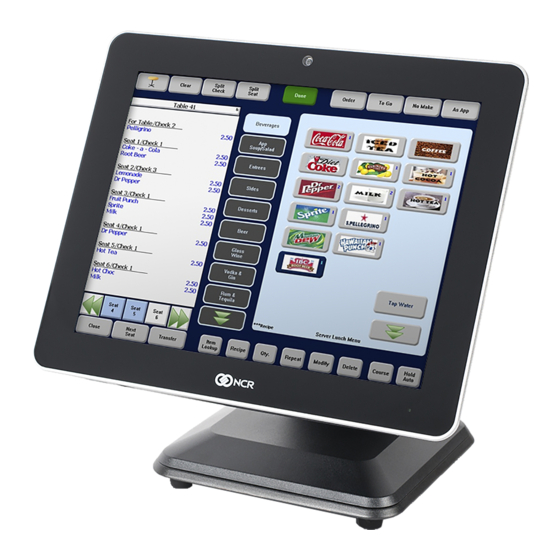
Chapter 1: Introduction The NCR P1535 is a Point-of-Sale (POS) terminal designed for the restaurant and food service environment. The terminal utilizes a next generation Intel® Celeron™ Processor N3160 (Quad core, 2.24 GHz). The highly efficient processor offers great performance, but with lower power consumption for a more reliable design. -
Page 11: Features And Benefits
(Quad core, 2.24 GHz). Quad-Core Technology Integrates four complete execution cores in a single processor providing advancements in simultaneous computing. NCR Countertop Enclosure Fully integrated, low-profile, water, and tamper resistant housing for high functional retail interaction. 15” XGA (1024x768) LED LCD Energy efficient and long life LED display. - Page 12 The fanless configuration increases reliability by preventing forced air through the unit, thereby reducing contaminants in the system. The P1535 is configured as a silent, thin-client, fanless, solid- state terminal for maximum reliability. Variable Position Tilt-Stand The tilt-stand provides variable tilt positions that are secured without need for pins or locking knobs.
-
Page 13: Optional Features And Benefits
7 powered serial ports. POE Expansion card Adds 1 x RJ45 power over Ethernet port, 1 x RJ45 serial port (powered 12 v), and 1xSIM card reader. Can be used to power an NCR Basestation4 to support Orderman devices. Quickserve Expansion Card Adds 1 x 24V Powered USB port, 1 x 12V powered USB port, and 2 x Cash Drawer ports via splitter cable from the terminal port. -
Page 14: Mounting Configurations
Product Overview Mounting Configurations... -
Page 15: Expansion Options
Product Overview Expansion Options... -
Page 16: Customer Display Options
Product Overview Customer Display Options... -
Page 17: Right Side Features (Port A)
Product Overview Right Side Features (Port A) -
Page 18: Left Side Features (Port B)
Product Overview Left Side Features (Port B) -
Page 19: Specifications
• (1) USB + Powered USB, 12 V This product does not support low speed USB devices Note: (1.5Mbit/s). NCR recommends using Full, High, and SuperSpeed USB devices to avoid a possible coexistence problem with higher speed peripherals in electrically noisy environments not following the NCR Workstation and Peripherals AC Wiring Guide (BSTO-2115-53). - Page 20 Product Overview 1-11 Features Specifications Cash Drawer Port (2) 12 V or 24 V Dual Cash Drawer Support A Y Cable is required when connecting to any 12 V Note: cash drawer or to dual cash drawers. HDMI Port (1) HDMI Port Display Port (1) Display Port Expansion ...
- Page 21 (P–Series Stand) Tilt Angle 3° to 111° from vertical Terminal Weight 7.39 kg (16.3 lbs) Varies by configuration. Refer to the NCR P1535 POS Note: (7761) Site Preparation Guide for more information. Shipping Weight 6.8 kg (15 lbs) 10.4 kg (23 lbs) – with P-Series Stand Operating Temperature 0°C –...
-
Page 22: Operator Controls
Product Overview 1-13 Operator Controls Power Switch The Power Switch is located as shown below. The switch can be accessed when the cable cover is opened or closed. Bezel LED The Front Panel Bezel LED has multiple functions as defined below. Color Description Black... -
Page 23: Label Locations
1-14 Product Overview Label Locations... -
Page 24: Chapter 2: Hardware Installation
• Install the NCR P1535 POS near an electrical outlet that is easily accessible. Use the power cord as a power disconnect device. • Do not permit any object to rest on the power cord. Do not locate the NCR P1535 POS where the power cord can be walked on. -
Page 25: Installation Notes
Power For tilt stand option, the P1535 has an integrated 19 V, 90 W power supply rated for 110 V and 240 V (Auto-sensing), 50 Hz or 60 Hz located in the base. With the powered USB 24 V option, the power supply is a 24V, 150 W external power brick rated for 110 V and 240 V (auto-sensing), 50Hz or 60Hz. -
Page 26: Magnetic Strip Reader (Msr) Cleaning
Periodically, the MSR may need to be cleaned depending on usage. Pre-saturated MSR cleaning cards can be ordered from NCR (50/box) using part number 1666-K024. Otherwise, wrap a card with a saturated paper towel of glass cleaner and swipe gently to clean reader head. -
Page 27: Ergonomic Workplace
Installation Notes and Restrictions Ergonomic Workplace The NCR P1535 POS has a high brightness LCD with an anti-glare screen but for best results please observe the following when considering the terminal workplace. • Avoid direct glaring and reflective glaring light. Locate the terminal in a controlled luminance surrounding. -
Page 28: Installing The Terminal
• X-Series Stand (7761-F172) • Wall Mount (7761-K001, 7761-K003) • Space Pole Mount (1668-K104, 7668-K105, 1668-K106) The NCR P1535 POS comes fully assembled and ready to use. All that is required is to connect the LAN Cable and peripheral device cables. Note: For other configurations, refer to the corresponding kit instructions. - Page 29 2-20 Installation Notes and Restrictions 2. Remove the Upper Stand Cover by pivoting it away from the stand. The cover has a simple snap fit connection at the top. 3. Loosen the thumbscrew to open the Cable Door.
- Page 30 Installation Notes and Restrictions 2-21 4. Loosen the screw on the Terminal Cable Cover. To open, press down on the indentations in the Cable Cover to unlatch the cover and then pivot the cover open. Note: Ensure that the screw is disengaged from the threads. 5.
- Page 31 2-22 Installation Notes and Restrictions 6. Connect the peripheral cables to the I/O Panel. Note: SIM cards must be inserted while the terminal is powered off. 7. Install the Terminal Cable Cover and tighten thumbscrew to secure cover. 8. Close the Cable Door and tighten thumbscrew to secure cable door. 9.
-
Page 32: Connecting Ac Power
Internet. To connect the P1535 terminal to a network, plug the 10/100/1000 Ethernet cable into the port labeled NETWORK on the bottom panel. The other end of the 10/100/1000 Ethernet cable should be connected into your network hub. -
Page 33: Installing A Transaction Printer
2-24 Installation Notes and Restrictions Installing a Transaction Printer Connect the printer to the USB port on the terminal. -
Page 34: Installing A Cash Drawer
Installation Notes and Restrictions 2-25 Installing a Cash Drawer The Cash Drawer can be connected to the Cash Drawer connector or to the transaction printer. -
Page 35: Second Cash Drawer Cable Connection
2-26 Installation Notes and Restrictions Second Cash Drawer Cable Connection The terminal supports a 2-drawer configuration with a Dual Cash Drawer Cable. Connect this cable to the terminal or transaction printer cash drawer connector. There are two versions of the Dual Cash Drawer Cable: •... -
Page 36: Using External Connectors
2-27 Using External Connectors In order to use the P1535 system to run your business' software, you can set up several peripheral components. The P1535 is compatible with standard PC equipment, including a USB mouse, USB keyboard, printer, speakers, network connectivity, as well as any other devices that can be supported by your operating system. -
Page 37: Rj12 Serial Port
12V at 500mA max. Pin Diagram Signal Name POWER/RTS RJ12 Adapter Kits If a peripheral device requires a different connector to connect to the P1535 POS terminal serial RJ12 connector, order the following adapter kits: RJ12 Adapter Kits 1639-K159 DB9M to RJ12 Adaptor (CN100381) -
Page 38: Rj45 Serial Port
Signal Name DTR/5V RTS/12V RJ45 Adapter Kits If a peripheral device requires a different connector to connect to the P1535 POS terminal serial RJ45 connector, order the following adapter kits: RJ45 Adapter Kits 1639–K332 RJ45 to DB25 Adapter Cable 1.85m 1639–K333... -
Page 39: Lan
2-30 Installation Notes and Restrictions The 7761 Motherboard provides 10/100/1000 Base T Ethernet support using Realtek RTL8111F controller. The 7761 Motherboard supports Wake on LAN. The connector features an integrated magnetic module and 2 LEDs. The LED on the left is yellow and indicates Link/Activity at 1GBit speed when lit/flashing. -
Page 40: Usb 3.0 Compliant Ports
Installation Notes and Restrictions 2-31 USB 3.0 Compliant Ports The 7761 Motherboard provides 4 USB 3.0 compliant ports. Each USB port is capable of supplying 5V at 900mA max. Pin Diagram Signal Name VBUS StdA_SSRX- StdA_SSRX+ GND_DRAIN StdA_SSTX- StdA_SSTX+ Shell Shield... -
Page 41: Cash Drawer (Cd) Port
2-32 Installation Notes and Restrictions Cash Drawer (CD) Port A single 6-position RJ12 connector (Molex 44248-0065 or NCR approved equivalent) is used. Pin Diagram Signal Name LOGIC GND SOLENOID A OPEN/CLOSE STATUS +24V SOLENOID B POWER GND Cash Drawer Cable Kits The terminal supports a 2–drawer configuration with a Dual Cash Drawer Cable. -
Page 42: Installing The Power Supply
Installation Notes and Restrictions 2-33 Installing the Power Supply If a power supply is not installed in the base of the P1535 terminal, install a 19 V power supply. Caution: The P1535 terminal requires the NCR 19 V or 24 V power supply that is shipped with the terminal. - Page 43 2-34 Installation Notes and Restrictions 4. Loosen the Thumbscrew that secures the Base Cover. 5. Slide the Base Cover toward the front slightly to disengage it from the Base.
- Page 44 Installation Notes and Restrictions 2-35 6. Route the AC Power Cord up through the base of the stand. 7. Attach the Power Cord to the Power Brick. 8. Install the Power Brick in the Base.
- Page 45 2-36 Installation Notes and Restrictions 9. Loosen the thumbscrew to open the Cable Door. 10. Loosen the screw on the Terminal Cable Cover. To open, press the indentations on the Cable Cover to unlatch the cover then pivot to open.
- Page 46 Installation Notes and Restrictions 2-37 11. Route the power cable up through the stand and connect the power supply cable to the Power In connector. 12. Secure the excess power cables with a cable tie and place the cables behind the Cable Door.
-
Page 47: Removing Top Assembly
2-38 Installation Notes and Restrictions Removing Top Assembly 1. Lay the terminal face down on a flat surface. Caution: Always use a soft material (cloth, foam) to protect the display screen when placing the terminal face down. 2. Remove the screws (2) that secure the Base Stand to the display. 3. -
Page 48: Terminal With Expansion
Installation Notes and Restrictions 2-39 Terminal with Expansion 1. Lay the terminal face down on a flat surface. Caution: Always use a soft material (cloth, foam) to protect the display screen when placing the terminal face down. 2. Remove the screws (2) that secure the expansion to the display. - Page 49 2-40 Installation Notes and Restrictions 3. Remove the stand and the Hinge Mount installed over the Expansion Board assembly. 4. Remove the screws (4) that secure the Expansion Board assembly.
-
Page 50: P1535 Pos
Appendix A: P1535 POS (7761) Description 7761-1500-8800 P1535 Res 40GB 8GB RAM WEPR7-32bit MMSR Int2x20 XD10 Wifi 7761-3000-8800 P1535 PCAP 40GB 4GB RAM WEPR7-32bit MSR 7761-3001-8800 P1535 PCAP 40GB 4GB RAM WEPR7-64bit MSR 7761-3002-8800 P1535 PCAP 60GB 4GB RAM WEPR7-64bit MSR... - Page 51 7761-3047-8801 P1535 PCAP 40GB 4GB RAM WEPR7-64bit MBlank EU Cord OM 7761-3048-8801 P1535 PCAP 40GB 4GB RAM WEPR7-64bit MSR EU Cord OM 7761-3049-8801 P1535 PCAP 120GB 8GB RAM WEPR7-64bit MSR Int2x20 SC Wifi EU Cord OM 7761-3050-8801 P1535 PCAP 60GB 4GB RAM WEPR7-64bit 2n1 EU Cord OM...
- Page 52 Product IDs Description 7761-3051-8801 P1535 PCAP 40GB 4GB RAM WEPR7-64bit 2n1 POE EU Cord OM 7761-3052-8801 P1535 PCAP 60GB 4GB RAM WEPR7-64bit 2n1 POE EU Cord OM 7761-3053-8801 P1535 PCAP 120GB 4GB RAM WEPR7-64bit 2n1 POE EU Cord OM 7761-3054-8801 P1535 PCAP 120GB 8GB RAM WEPR7-64bit 2n1 POE EU Cord OM...
- Page 53 Product IDs Description 7761-3100-0078 P1535 PCAP 60GB 4GB RAM Win10E-64bit MSR XD10 BIO 7761-3100-0079 P1535 PCAP 60GB 4GB RAM Win10E-64bit MSR Int2x20 BIO 7761-3100-0080 P1535 PCAP 120GB 4GB RAM Win10E-64bit MSR Int2x20 BIO 7761-3100-0081 P1535 PCAP 60GB 8GB RAM Win10E-64bit MSR Int2x20 BIO...
- Page 54 7761-3100-0162 P1535 PCAP 40GB 4GB RAM WEPR7-32bit MSR Int2x20 no Cord 7761-3100-0163 P1535 PCAP 40GB 4GB RAM WEPR7-32bit MSR BIO no Cord 7761-3100-0164 P1535 PCAP 40GB 4GB RAM WEPR7-64bit MSR Int2x20 BIO no Cord 7761-3100-0165 P1535 PCAP 60GB 4GB RAM Win10E-64bit MSR no Cord...
- Page 55 7761-3100-0181 P1535 PCAP 120GB 4GB RAM Win10E-64bit MSR XD10 no Cord 7761-3100-0182 P1535 PCAP 120GB 8GB RAM Win10E-64bit MSR XD10 no Cord 7761-3100-0183 P1535 PCAP 60GB 4GB RAM Win10E-64bit MSR XD10 BIO no Cord 7761-3100-0184 P1535 PCAP 60GB 4GB RAM Win10E-64bit MSR Int2x20 BIO no Cord...
- Page 56 7761-3100-0210 P1535 PCAP 60GB 4GB RAM WEPR7-32bit MSR RJ12 7761-3100-0211 P1535 PCAP 120GB 4GB RAM WEPR7-32bit MSR RJ12 7761-3100-0212 P1535 PCAP 120GB 4GB RAM WEPR7-32bit MSR XR-STAND BIO PUSB 150W 7761-3100-0213 P1535 PCAP 120GB 8GB RAM WEPR7-32bit MSR XD10 7761-3100-0214 P1535 PCAP 40GB 4GB RAM Android MSR...
- Page 57 7761-3101-0123 P1535 PCAP 60GB 4GB RAM No OS MSR EU Cord 7761-3101-0124 P1535 PCAP 60GB 4GB RAM No OS MBlank EU Cord 7761-3101-0125 P1535 PCAP 120GB 4GB RAM No OS MSR Int2x20 SC Wifi EU Cord 7761-3101-0126 P1535 PCAP 120GB 4GB RAM No OS MBlank EU Cord...
- Page 58 7761-3101-0128 P1535 PCAP 40GB 4GB RAM No OS MBlank XB EU Cord 7761-3101-0129 P1535 PCAP 40GB 4GB RAM No OS 2n1 XB EU Cord 7761-3101-0130 P1535 PCAP 40GB 4GB RAM No OS MBlank Int2x20 XB EU Cord 7761-3101-0131 P1535 PCAP 40GB 4GB RAM No OS MSR XB EU Cord...
- Page 59 7761-3101-0171 P1535 PCAP 120GB 4GB RAM WEPR7-64bit MSR 2x20DB CHINA 7761-3101-0172 P1535 PCAP 40GB 8GB RAM WEPR7-64bit MSR BIO CHINA 7761-3101-0173 P1535 PCAP 40GB 4GB RAM WEPR7-64bit MSR 2x20DB BIO CHINA 7761-3101-0174 P1535 PCAP 40GB 8GB RAM WEPR7-64bit MSR 2x20DB BIO CHINA...
- Page 60 7761-3101-0204 P1535 PCAP 60GB 4GB RAM WEPR7-32bit MSR Int2x20 EU Cord 7761-3101-0205 P1535 PCAP 60GB 4GB RAM WEPR7-32bit MSR Int2x20 BIO UK Cord 7761-3101-0206 P1535 PCAP 60GB 4GB RAM WEPR7-32bit MSR Int2x20 BIO EU Cord 7761-3500-8800 P1535 PCAP 40GB 4GB RAM WEPR7-32bit MSR Int2x20 Ext2x20 BIO/SC Cam Wifi...
Need help?
Do you have a question about the P1535 and is the answer not in the manual?
Questions and answers