
Related Manuals for Martel MC1210


Summary of Contents for Martel MC1210
- Page 1 MC1210 Reference Manual GlobalTestSupply www. .com Find Quality Products Online at: sales@GlobalTestSupply.com...
-
Page 2: Table Of Contents
1. Introduction ............. . .3 1.1 Customer Service . -
Page 3: Introduction
1. Introduction The Martel MC1210 Multifunction Process Calibrator is a handheld, battery-operated instrument that measures and sources electrical and physical parameters. The calibrator has the following features and functions: • A dual display. The upper display is used for the measurement of volts, current, and pressure. -
Page 4: Safety Information
1.3 Safety information Symbols Used The following table lists the International Electrical Symbols. Some or all of these symbols may be used on the instrument or in this manual. Symbol Description AC (Alternating Current) AC-DC Battery CE Complies with European Union Directives Double Insulated Electric Shock Fuse... - Page 5 Warning To avoid possible electric shock or personal injury: • Do not apply more than the rated voltage. See specifications for supported ranges. • Follow all equipment safety procedures. • Never touch the probe to a voltage source when the test leads are plugged into the current terminals.
-
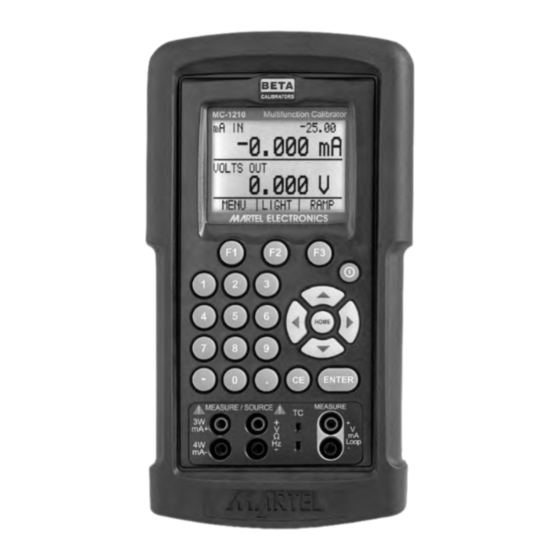
Page 6: Calibrator Interface
2. Calibrator Interface Figure 1 shows the location of the input and output connections on the calibrator, while Table 1 describes their use. HOME – ENTER Figure 1. Input/Output Terminals Table 1: Input and Output Terminals Name Description 1, 2 Measure Isolated V, Input terminals for measuring current, voltage, switchtest, mA terminals, switchtest... -
Page 7: Main Display
Figure 2 shows the location of the keys on the calibrator. Table 2 lists the functions of each key. HOME – ENTER Figure 2. Keypad Table 2. Key Functions Name Function Function Keys F1, F2, F3 Used to operate the menu bar at the bottom of the calibrator display. -
Page 8: Menu Bar
The display of the calibrator, shown in Figure 3, is divided into three main sections: the upper display, the lower display, and the menu bar. The upper display is used for measuring dc voltage, dc current with and without loop power, and pressure. - Page 9 [DONE] returns to home menu. Contrast is adjusted using the arrow options, which are available after choosing [CONTRAST]. NOTE: The MC1210 calibrator offers a wide range contrast adjustment feature to accommodate operation in extreme temperatures. In certain cases making large changes in contrast may render the display difficult to read under normal conditions.
- Page 10 1. Turn on the unit while holding down the “HOME” key. 2. Hold the key down for a count of 10 seconds to restore contrast default settings. If the display is so dim that you cannot tell if the unit is on or off, use the backlight key to determine if the power is on or off.
-
Page 11: Cursor Control / Setpoint Control
2.3 Cursor control / Setpoint control The output value can be controlled by the four cursor control arrows on the keypad. By pressing one of the arrows a cursor will be added to the display under the last digit of the output value. -
Page 12: Using Measure Modes (Lower Display)
3. Using Measure Modes (Lower Display) 3.1 Measuring volts and frequency Electrical parameters volts and frequency can be measured using the lower display. To make the desired measurements, follow these steps: 1. Switch to the lower display [LOWER] from Main Menu. 2. -
Page 13: Measuring Temperature
3.3 Measuring Temperature 3.3-1 Using Thermocouples The calibrator supports the following thermocouple types: B, C, E, J, K, L, N, R, S, T, U, BP , and XK. The characteristics of all the types are described in Specifications section. The calibrator also has a Cold Junction Compensation (CJC) function. -
Page 14: Measuring Pressure
RTD which is not programmed into the calibrator. 3.4 Measuring Pressure Note: The MC1210 is compatible with BETA Calibrator Pressure Modules. The accessory BPPA-100 is required for pressure measurement. Note: Pressure is not read from modules with frequency or pulse train mode enabled. - Page 15 To measure pressure, follow these steps: 1. Connect the pressure module to the calibrator as shown in Figure 9. The calibrator can measure pressure on both the upper and the lower display. This makes it possible to measure pressure in two different units at the same time. Note: Make sure the calibrator is on before you plug in the pressure module.
-
Page 16: Using Source Modes (Lower Display)
4. Using Source Modes (Lower Display) The calibrator can generate calibrated signals for testing and calibrating process instruments. It can source voltages, currents, resistances, frequencies, pulses, and the electrical output of RTD and thermocouple temperature sensors. 4.1 Setting 0% and 100% Output Parameters To set the 0% and 100% points, use the following steps: 1. - Page 17 Figure 10. Connections for Sourcing Current 4.3-1 HART™ Resistor Selection The MC1210 can be set-up so that the 250 ohm resistor required for Hart™ configuration devices resides inside the MC1210. Enabling the MC1210's internal 250 ohm resistor eliminates the need to manually add a series resistor during a Hart™ calibration process.
-
Page 18: Simulating A Transmitter
4.4 Simulating a Transmitter To have the calibrator supply a variable test current to a loop in place of a transmitter, follow these steps: 1. Select lower display from the Main Menu. 2. Choose mA simulation from the primary parameters [mA 2W SIM], and enter the desired current. -
Page 19: Sourcing Frequency
4.6 Sourcing frequency To source a signal use these steps: 1. Switch to the lower display and select frequency from the primary parameters. 2. Select output, and than choose the frequency units. 3. Connect the leads to the frequency output terminals as shown in Figure 12. 4. -
Page 20: Sourcing Thermocouples
Figure 13. Connections for Outputting Thermocouples 4.8 Sourcing Thermocouples To source a thermocouple use the following steps: 1. Connect the thermocouple leads to the appropriate polarized TC miniplug, and insert the plug into the TC terminals on the calibrator, as shown in Figure 13. 2. -
Page 21: Sourcing Ohms/Rtds
4.9 Sourcing Ohms/RTDs To source an RTD, follow these steps: 1. Select lower display from the Main Menu, and choose [RTD] from the primary parameters. 2. Choose output [OUT] from the input/output control, and select RTD type from the sensor types. -
Page 22: Using Isolated Measure Modes (Upper Display)
temperature, maximum temperature, R0, and the values for each of the temperature coefficients. The custom function uses the Calendar-Van Dusen equation for outputting and measuring custom RTDs. The coefficient C is only used for temperatures below 0°C. Only A and B coefficients are needed for the range above 0°C, so coefficient C should be set to 0. -
Page 23: Measuring Pressure
Figure 17. Connection Using Current Loop 5.2-1 HART™ Resistor Selection The MC1210 can be set-up so that the 250 ohm resistor required for Hart™ configuration devices resides inside the MC1210. Enabling the MC1210's internal 250 ohm resistor eliminates the need to manually add a series resistor during a Hart™ calibration process. - Page 24 Caution To avoid mechanically damaging the pressure module, never apply more than 10 ft-lb. of torque between the pressure module fittings, or between the fittings an the body of the module. To avoid damaging the pressure module from overpressure, never apply pressure above the rated maximum printed on the module.
-
Page 25: Using The Upper And The Lower Display For Calibration And Testing
6. Using the Upper and the Lower Display for Calibration and Testing 6.1 Testing an Input or Indicating Device To test and calibrate actuators, recording, and indicating devices using the source functions, follow these steps: 1. Select the lower display and choose the correct primary parameter. 2. -
Page 26: Calibrating A Transmitter
6.3 Calibrating a Transmitter To calibrate a transmitter both the upper and the lower displays will be used; one for measuring and the second a source. This section covers all but the pressure transmitters. A thermocouple temperature transmitter is used in this example. The following steps show how to calibrate a temperature transmitter: 1. -
Page 27: Performing A Switch Test
– HOME – ENTER PRESSURE MODULE HAND PUMP Figure 22. Calibrating a Pressure Transmitter 7. Performing a Switch Test The calibrator can stimulate a switch and capture the results in any source/simulate mode (except pulse) and the calibrator can also monitor a switch and capture the results in any read mode based on the input requirements of the switch. - Page 28 1. Use the menu to select SW TEST on the upper display. 2. Connect the calibrator to the switch using the switch terminals. The polarity of the terminals does not matter. 3. The top of the display will read “CLOSE”. SW TEST CLOSE ------ °C P100-385...
-
Page 29: Performing A Pressure Switch Test
7.2 Performing a pressure switch test: Pressure Switch HOME – ENTER PRESSURE MODULE HAND PUMP Figure 24. Pressure Switch Test 1. Use the menu to select SW TEST on the upper display. 2. Connect the calibrator to the switch using the pressure switch terminals. The polarity of the terminals does not matter. - Page 30 SW TEST OPEN ------ 28.000 LIGHT MENU 7. At the top of the display it will now read, “SW OPENED AT” and give you the pressure that the switch opened at. SW OPENED AT 30.000 28.000 LIGHT MENU 8. Press the “NEXT” option to view when the switch closed, and the dead band. Important NOTE: The previous example uses a normally closed switch.
-
Page 31: Remote Operation
1. Start Hyper Terminal (located in Accessories/Communications of the Windows Start menu) 2. Select New Connection. 3. For Name enter MC1210. Select the serial port that the unit is connected to. 4. Enter the above information for port settings. 5. Select ASCII setup from File/Properties/Settings and mark these choices:... -
Page 32: Changing Between Remote And Local Operation
6. Select Ok 7. To see if the port works enter *IDN?. This command will return information on the unit. 8.2 Changing Between Remote and Local Operation There are three modes of operation of the calibrator, Local, Remote, and Remote with Lockout. - Page 33 Compound Commands Commands that contain more than one command on one line. For example: LOWER_MEAS RTD; RTD_TYPE CU10 Sets the calibrator to measure RTD in the lower display and sets RTD type to Cu 10. Overlapped Commands Commands that require more time to execute than normal. The command *WAI can be used after the overlapped command to tell the calibrator to wait until the command finishes before executing the next command.
- Page 34 Indefinite ASCII (IAD) Any ASCII characters followed by a terminator. For example: *IDN? returns MARTEL, MC1210, 250, 1.00 8.3-4 Calibrator Status Status registers, enable registers, and queues provide status information on the calibrator. Each status register and queue has a summary bit in the Serial Poll Status Byte. Enable registers generate summary bits in the Serial Poll Status Byte.
- Page 35 ESR, and setting it to 0 disables the corresponding bit. Cleared at power reset. Bit assignments for the ESR and the ESE respectively are shown below. Power On. Set to 1 if power was turned on and off before the Event Status Register was read.
-
Page 36: Remote Commands And Error Codes
Input Buffer Calibrator stores all received data in the input buffer. The buffer holds 250 characters. The characters are processed on a first in, first out basis. 8.4 Remote Commands and Error Codes The following tables list all commands, and their descriptions, that are accepted by the calibrator. - Page 37 Command Description CPRT_COEFC Sets the custom RTD coefficient C CPRT_COEFC? Returns the custom RTD coefficient C CPRT_MIN_T Sets the custom RTD minimum temperature CPRT_MIN_T? Returns the custom RTD minimum temperature CPRT_MAX_T Sets the custom RTD maximum temperature CPRT_MAX_T? Returns the custom RTD maximum temperature CPRT_R0 Sets the custom RTD R0 resistance CPRT_R0?
- Page 38 Command Description TC_TYPE? Returns the thermocouple type TEMP_UNIT Sets input/output temperature unit for RTD and TC TEMP_UNIT? Returns the temperature unit for RTD and TC TRIG Starts and stops the pulse train in pulse mode TRIG? Returns TRIGGERED when a pulse train is on. Returns UNTRIGGERED when the pulse train is off.
-
Page 39: Entering Commands
Units Meaning MMH2O4C Pressure in millimeters of water at 4°C MMH2O20C Pressure in millimeters of water at 20°C FTH2O60F Pressure in feet of water at 60°F Table 8: Error codes Error Number Error Description A non-numeric entry was received where it should be a numeric entry Too many significant digits entered Invalid units or parameter value received Entry is above the upper limit of the allowable range... - Page 40 *IDN? Returns the manufacturer, model number, and firmware revision of the Calibrator. For example: *IDN? will return MARTEL, MC1210, 250, 1.00 *OPC Enables the Operation Complete setting in the ESR. This setting makes it possible to check if an operations is complete after it has been initialized.
- Page 41 *SRE? Returns a byte from the SRE. The byte is returned in decimal format. For example: If 40 is returned, bits 5 and 3 are enabled. *STB Returns the status byte in decimal form from the Serial Poll Status Byte. For example; If 72 is returned, bits 6 and 3 are enabled.
- Page 42 CPRT_COEFA? Returns the number which was entered for the first coefficient of the polynomial used in the custom RTD. Using the example above CPRT_COEFA? Would return: 3.908000E-03 CPRT_COEFB This command is used for entering a custom RTD into the calibrator. The numeric value entered after the command will be set as the second coefficient of the polynomial used by the custom RTD.
- Page 43 CPRT_MAX_T Sets the maximum temperature of the custom RTD range. The temperature value must be entered with a degrees label, CEL for Celsius and FAR for Fahrenheit. For example: CPRT_MAX_T 0.0 CEL enters 0.0°C as the maximum temperature. CPRT_MIN_T? Returns the value entered for minimum temperature in the range for a custom RTD. The above example would return: 0.000000E+00, CEL CPRT_R0...
- Page 44 FREQ_TYPE When in frequency mode, sets the calibrator to output a continuous wave (Frequency Out), or a pulse train. To set the calibrator to continuous wave enter CONT after the command. To set the calibrator to pulse enter PULSE after the command. For example: FREQ_TYPE CONT will set the calibrator to FREQ OUT.
- Page 45 Returns the model and serial number of the attached pressure unit. Returns NONE if no pressure unit is attached. For example: PRES? Will return MARTEL,001PNS,3,0 PRES_UNIT? Returns the pressure units of both the upper and the lower display. For example if the unit on...
- Page 46 RTD_TYPE Sets the RTD type. The following is a list of RTD types they way they should be entered after the command: PT385_10; PT385_50; PT385_100; PT385_200; PT385_500; PT385_1000; PT392_100; PTJIS_100; Ni120; Cu10; Cu50; Cu100; YSI_400; OHMS; CUSTOM; For example: RTD_TYPE PT385_10 sets RTD type to Pt385-10 RTD_TYPE? Returns the RTD type.
- Page 47 ST_START Starts a switch test. TC_TYPE Sets the type of the thermocouple. All available types are shown in the TC Types table in Section 8. (Specifications). For example: TC_TYPE B sets thermocouple type to B TC_TYPE? Returns the type of thermocouple the calibrator is set to. TEMP_UNIT Sets the temperature unit for sourcing and measuring RTD and TC.
- Page 48 U_PRES_UNIT Sets the unit for measuring pressure on the upper display. Add the unit after the command. The available pressure units and their syntax are shown in Table 7. (Parameter Units). For example: U_PRES_UNIT MMHG sets the pressure unit to millimeters of mercury at 0°C VAL? Returns the value of any measurement taking place on the upper and lower display.
-
Page 49: Specifications
9. Specifications One year at 23°C ± 5°C, unless specified otherwise. Outside of this range the stability of the measurements is ± 0.003% of FS/°C. Table 9: General Specifications Operating Temperature -10°C to 50°C Storage Temperature -20°C to 60°C Power 4 X AA batteries;... - Page 50 Table 12: Frequency Measurement/Source Range Accuracy (% of reading ± floor) Read 2.0CPM - 600.0CPM 0.05% ± 0.1CPM 1.0Hz - 1000.0Hz 0.05% ± 0.1Hz 1.00KHz - 10.00KHz 0.05% ± 0.01KHz Source 2.0CPM - 600.0CPM 0.05% 1.0Hz - 1000.0Hz 0.05% 1.00KHz - 10.00KHz 0.250% Input voltage amplitude range on frequency is 1V to 20V zero based square wave only.Output amplitude is adjustable from 1V to 20V, and is a square wave with 50% duty cycle.For output frequency, a slight negative...
- Page 51 -250.0 -200.0 -200.0 400.0 -250.0 -200.0 -200.0 -100.0 -100.0 1000.0 200.0 200.0 1767.0 200.0 200.0 1767.0 600.0 800.0 800.0 1000.0 1000.0 1820.0 1000.0 1000.0 2316.0 -200.0 800.0 800.0 800.0 2500.0 -200.0 900.0 -200.0 600.0 -200.0 -100.0 -100.0 1300.0 CJC error outside of 23 ± 5°C is 0.05°C/°C 1.
- Page 52 RTD Type Range (°C) Accuracy (°C) Minimum Maximum Measure 4W/Source Measure 3W 300.0 400.0 400.0 630.0 630.0 800.0 PT385, 100 ohm -200.0 -80.0 -80.0 100.0 100.0 300.0 300.0 400.0 400.0 630.0 630.0 800.0 PT3926, 100 ohm -200.0 -80.0 -80.0 100.0 100.0 300.0 300.0...
-
Page 53: Maintenance / Warranty
10.1 Replacing Batteries Replace batteries as soon as the battery indicator turns on to avoid false measurements. If the batteries discharge too deeply the MC1210 will automatically shut down to avoid battery leakage. Note: Use only AA size alkaline batteries or optional rechargeable batteries. -
Page 54: Service Center Calibration Or Repair
Battery Adapter/Charger 10.5 Warranty Martel Electronics Corporation warrants all products against material defects and workmanship for a period of twelve (12) months after the date of shipment. Problems or defects that arise from misuse or abuse of the instrument are not covered. If any product is to be returned, a “Return Material Authorization”...
Need help?
Do you have a question about the MC1210 and is the answer not in the manual?
Questions and answers