
Related Manuals for Martel 3001


Summary of Contents for Martel 3001
- Page 1 3001 Operator’s Manual GlobalTestSupply www. .com Find Quality Products Online at: sales@GlobalTestSupply.com...
-
Page 2: Table Of Contents
3001 Operator’s Manual 1. Introduction ............1 1.1 Customer Service . - Page 3 9.7 Checking 3001 Status ........
-
Page 4: Introduction
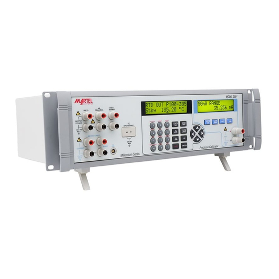
1. Introduction The Martel series 3001 calibrator is an accurate full-featured temperature, pressure and DC calibrator intended for R & D, manufacturing and calibration lab applications. The unit's simple design and ease of operation allow users to quickly familiarize themselves with its operations and features. -
Page 5: Safety Information
• AC Line Cord • Thermocouple Shorting Jumper • NIST Certificate Safety Information Symbols Used The following table lists the International Electrical Symbols. Some or all of these symbols may be used on the instrument or in this manual. Symbol Description AC (Alternating Current) AC-DC... - Page 6 The following definitions apply to the terms "Warning" and "Caution". • " Warning" identifies conditions and actions that may pose hazards to the user. • " Caution" identifies conditions and actions that may damage the instrument being used. Use the calibrator only as specified in this manual, otherwise personal injury and/or damage to the calibrator may occur.
-
Page 7: Calibrator Description
• To avoid damaging the pressure module from corrosion, use it only with specified materials. Refer to the pressure module documentation for material compatibility. Make sure to remove all test connections before powering up the 3001. Failure to do so could lead to damage of the 3001 or the unit under test. -
Page 8: Primary Input/Output Terminals
2.2 Primary Input/Output Terminals Figure 2 describes the primary input/output terminals in detail. The display and controls for these terminals are described in the next section. Figure 2 - Primary Input/Output Terminals Item Name Description VOLTS DC voltage output terminals. See notes 1 and 2 below. DC current output terminals. -
Page 9: Primary Input/Output Display And Controls
2.3 Primary Input/Output Display and Controls Figure 3 describes the primary input/output display and controls in detail. Figure 3 - Primary Input/Output Display and Controls Item Name Description Display A 2 line, 16 character, display providing all visual user feedback for the primary output and input operations.See section 2.6 for layout details, and section 2.7 for possible error messages. - Page 10 RNG LOCK Select Auto-range or Range Lock for voltage output. LOCAL Press to regain local control of the 3001 after the remote command REMOTE has been received; in this case all keys except this one are ignored. When the remote com-...
-
Page 11: Isolated Input Display, Controls, And Terminals
Clears a partial keypad entry and reverts the calibrator out- put or parameter to its last known value. Prepares for selection of a secondary function via the numeric keypad according to the text above each key. The display changes to SHIFT ENABLED until a numeric key is pressed. - Page 12 Item Name Description Display A 2 line, 16 character, display providing all visual user feedback for the isolated input operations. See section 2.6 for layout details, and section 2.7 for possible error mes- sages. Function keys Select DC voltage and current input mode. Subsequent presses of this key cycle through the ranges: 10V, 100V, and 50mA.
-
Page 13: Rear Panel
Figure 5 - Rear Panel Item Description RS-232 9 pin connector for remote control of the 3001 via any computer's serial interface. GPIB IEEE 488.2 connector for remote control of the 3001 via a GPIB bus. Service port for updating the 3001 firmware. -
Page 14: Display Layouts
2.6 Display Layouts a) Primary Voltage and Current Display Figure 6 - Primary Voltage and Current Display Layout Item Description Operating mode: AUTO: Auto-range LOCK: Range lock remote operation Automatic stepping of preset setpoints Present range and output mode Output state: Stby Standby, terminals inactive Operating, terminals are active with output per the displayed value... - Page 15 Blank for RTD inputs Cold junction selection for thermocouple inputs and outputs: XCJC External cold junction compensation; the 3001 automatic cold junction compensation is turned off, i.e. 0 mV is always 0°C Blank Internal cold junction compensation; the 3001 automatically measures the ambient temperature at the thermocouple terminals and compen- sates the measurement, i.e.
-
Page 16: Error Messages
OVER LOAD For DC voltage output mode, the current required to generate the output exceeds the 3001 specifications.For DC current mode, the resistance of the circuit exceeds the 3001 specifications. For input modes, the measured value exceeds the upper limit of the selected input mode range.For output modes, when the range is locked, the present... -
Page 17: Getting Started
4. Primary Inputs and Outputs 4.1 DC Voltage Output The 3001 can source DC voltages from 0 V to 100 V, using the following four ranges for maximum accuracy: .1 V, 1 V, 10 V, and 100 V. a) Disconnect any test leads from external devices. -
Page 18: Dc Current Output
• Warning. Automatic setpoints over 30V will not place the 3001 in standby mode for each new value. The 3001 can be locked to a specific voltage range by entering a value in that range and then selecting the secondary RNG LOCK function by pressing the keys. -
Page 19: Resistance Temperature Detector (Rtd) And Ohms Measure
Connect the unit under test to the current output terminals of the 3001 as shown in figure 11. Figure 11 - DC Current Output Connection d) Use the numeric keypad to enter the desired output value and press the key. - Page 20 The set up and use of custom RTD coefficients is described in section 4.5. The set up and use of SPRT coefficients is described in section 4.6. e) Connect the unit under test to the 4 wire RTD/Ω input terminals of the 3001 as shown in figure 12.
-
Page 21: Resistance Temperature Detector (Rtd) And Ohms Source
4.4 Resistance Temperature Detector (RTD) and Ohms Source The 3001 can source all common RTD types and 5 custom RTD curves in °F or °C, plus basic resistance from 5 to 4000 ohms. The following common RTD types are supported: Pt 385 100Ω, 200Ω, 500Ω, 1000Ω... -
Page 22: Resistance Temperature Detector (Rtd) With Custom Coefficients
When RTD/Ω mode is first selected, the 3001 is placed in the standby (Stby) mode which puts the positive (+) output jack into a high impedance state (>100k ohm) for safety. To place the output into the active state, press the key which toggles between the standby and operate modes. -
Page 23: Standard Platinum Resistance Thermometer (Sprt) Coefficients
-4.2325e10-12 Standard Platinum Resistance Thermometer (SPRT) Coefficients The SPRT function of the 3001 uses ITS-90 standard coefficients as a basis for measuring a SPRT. The five custom coefficients are entered as deviations from the standard coefficients, and as such, all of them are set to zero at the factory. -
Page 24: Thermocouple (T/C) Measure
SPRT selection prompt. 4.7 Thermocouple (T/C) Measure The 3001 can measure all common thermocouple types in °F or °C, plus basic millivolts from -10.0 to 75.0 mV. The following common thermocouple types are supported: B, C, E, J, K, L, N, R, S, T, U, XK, BP a) Disconnect any test leads from external devices. - Page 25 For best accuracy, it is advisable to zero the T/C millivolt circuit daily, or if the 3001 is being used outside of the ambient temperature range of 18 to 28 °C. The maximum offset from unit calibration that can be zeroed out is ±1 mV.
-
Page 26: Thermocouple (Tc) Source
4.8 Thermocouple (TC) Source The 3001 can source all common thermocouple types in °F or °C, plus basic millivolts from -10.0 to 75.0 mV. The following common thermocouple types are supported: B, C, E, J, K, L, N, R, S, T, U, XK, BP a) Disconnect any test leads from external devices. -
Page 27: Pressure Measure
For best accuracy, it is advisable to zero the T/C millivolt circuit daily, or if the 3001 is being used outside of the ambient temperature range of 18 to 28 °C. This procedure is described in section 4.7 on thermocouple measurements. -
Page 28: Isolated Inputs
5. Isolated Inputs 5.1 Voltage Input The 3001 can measure DC voltages from 0 V to 100 V, using the following two ranges for maximum accuracy: 10 V, and 100 V. a) Disconnect any test leads from external devices. b) Press the key to select isolated DC voltage and current input mode, if not already selected. -
Page 29: Pressure Input
If a 250 ohm resistor is required during a HART calibration procedure, press the key to switch in the 3001 internal 250 ohm resistor. The word HART is appended to the top line of the display to indicate that the resistor is switched in. -
Page 30: Output Setpoints
Press the key. The 3001 automatically senses which pressure module is attached and sets its range accordingly. c) If necessary, press the key again to cycle through the pressure units until the desired one is displayed. d) Before attaching the module to the pressure source, zero the module as described in the instruction sheet that came with the module. -
Page 31: Application Notes
At the setpoint number selection prompt "RECALL SPT#", press the numeric key, 1 to 9, corresponding to the setpoint to be recalled. To start an automatic setpoint cycle: Select the output mode. Press the keys to select the AUTOSET function. At the ending setpoint number selection prompt "AUTO SET POINT", press the numeric key, 1 to 9, corresponding to the ending setpoint number for the cycle. -
Page 32: I/P Transmitter
1. Disconnect any test leads from external devices. 2. Select pressure input on the primary display as described in section 4.9. 3. Select current input on the isolated display as described in section 5.2. Select the isolated loop power option. If a HART communicator is to be used for set up of the transmitter, select the HART option. -
Page 33: Transmitter
7.3 V/I Transmitter Figure 22 - V/I Transmitter Application 1. Disconnect any test leads from external devices. 2. Select voltage output on the primary display as described in section 4.1 3. Select current input on the isolated display as described in section 5.2. Select the isolated loop power option. -
Page 34: Rtd Transmitter
1. Disconnect any test leads from external devices. 2. Select RTD input on the primary display as described in section 4.3. Select the RTD type which corresponds to the RTD being tested. 3. Connect the RTD as shown in figure 23. 4. -
Page 35: Thermocouple Test
Thermocouple Test Figure 25 - Thermocouple Test Application 1. Disconnect any test leads from external devices. 2. Select thermocouple input on the primary display as described in section 4.7. Select the thermocouple type which corresponds to the thermocouple being tested. 3. -
Page 36: Rtd Indicator
1. Disconnect any test leads from external devices. 2. Select thermocouple output on the primary display as described in section 4.8. Select the thermocouple type which corresponds to the transmitter being tested. 3. Select current input on the isolated display as described in section 5.2. Select the isolated loop power option. -
Page 37: Precision Current Trip
Precision Current Trip Figure 28 - Precision Current Trip Application 1. Disconnect any test leads from external devices. 2. Select current output on the primary display as described in section 4.2. 3. Select voltage input on the isolated display as described in section 5.1. 4. -
Page 38: I/I Isolator/Transmitter
7.10 I/I Isolator/Transmitter Figure 29 - I/I Isolator/Transmitter Application 1. Disconnect any test leads from external devices. 2. Select current output on the primary display as described in section 4.2. 3. Select current input on the isolated display as described in section 5.2. Select the isolated loop power option. -
Page 39: Precision Temperature Measurement With Ibp-2 Probe
7.11 Precision Temperature Measurement with IBP-2 Probe Figure 30 - Precision Temperature Measurement with IBP-2 Probe 1. With the IBP-2 probe and the corresponding custom coefficients, the total system error is 0.03°C. 2. Disconnect any test leads from external devices. 3. -
Page 40: Lcd And Remote Interface Setup Procedures
9. Remote Interface 9.1 Introduction The 3001 can be controlled remotely from a personal computer (PC) using either a RS- 232 serial connection or an IEEE-488 parallel connection (also called a General Purpose Interface Bus, or GPIB, connection). In either case, individual commands can be typed into a terminal emulator program suitable for the connection type, or the calibrator can be controlled by an automated PC program using the 3001 command set. -
Page 41: Setting Up The Rs-232 Port For Remote Control
9.2.1 Using the 3001 on Computers with USB Ports The 3001 can be used with a computer having only USB ports with the use of a USB to serial converter. Martel can provide the following equipment to support this connection: •... -
Page 42: Changing Between Local And Remote Operation
Figure 32 - IEEE-488 (GPIB) Remote Connection 9.4 Changing Between Local and Remote Operation In addition to local mode (front panel operation) and remote, the 3001 can be placed into a local lockout condition at any time by command of the controller. Combined, the local, remote, and lockout conditions yield four possible operating states as follows. -
Page 43: Ieee-488 Interface Overview
IEEE Standards. For example, the command REMOTE could be sent as data over the IEEE-488 interface to place the 3001 into remote operating mode, but it is not because the IEEE Standards call for the remote function to be sent to the device as the uniline message REN. -
Page 44: Using Commands
All commands, units, and text data may be entered in UPPER or lower case letters. The 3001 converts all lower case letters to upper case before processing. 9.6.1 Types of Commands The commands for the 3001 can be grouped into the following categories based on how they function. Device-Dependent Commands Device-dependent commands are unique to the 3001. - Page 45 OPER These could be combined into the compound command: OUT 1 V; OPER These commands instruct the 3001 to source 1 V DC, and then go into operate mode. Overlapped Commands Commands that begin execution but require slightly more time than the normal communication command/response interval to complete are called overlapped commands.
- Page 46 For these commands, the detailed command descriptions in section 10 show a check mark beside RS-232, but no check mark beside IEEE-488. Table 6 - Commands for RS-232 Only IEEE-488 Message RS-232 Equivalent LOCAL command REMOTE command LOCKOUT command Commands for IEEE-488 These are all of the commands except for those used for RS-232 only, as described above.
- Page 47 inH2O4C Pressure in inches of water at 4 °C inH2O20C Pressure in inches of water at 20 °C inH2O60F Pressure in inches of water at 60 °F cmH2O4C Pressure in centimeters of water at 4 °C cmH2O20C Pressure in centimeters of water at 20 °C mmH2O4C Pressure in millimeters of water at 4 °C mmH2O20C...
-
Page 48: Checking 3001 Status
Some registers and queues are defined by the IEEE-488.2 standard, while the rest are specific to the 3001. In addition to the status registers, the Service Request (SRQ) control line and a 16-element buffer called the Error Queue provide also status information. - Page 49 Figure 33 - Status Register Overview Table 9 lists the status registers and gives the read/write commands and associated mask registers used to access them. Table 9 - Status Register Summary Status Register Read Command Write Command Serial Poll Status Byte (STB) *STB? —...
- Page 50 Requesting service. The RQS bit is set to 1 whenever bits ESB, MAV, EAV, or ISCB change from 0 to 1 and are enabled (1) in the SRE. When RQS is 1, the 3001 asserts the SRQ control line on the IEEE-488 interface. You can do a serial poll to read this bit to see if the 3001 is the source of an SRQ.
- Page 51 ESB bit in the Serial Poll Status Byte also goes to 1. The ESR bit stays 1 until the controller reads the ESR, does a device clear, a selected device clear, or sends the reset or *CLS command to the 3001. The ESE is cleared (set to 0) when the power is turned on.
- Page 52 11) Input Buffer Operation As the 3001 receives each data byte from the controller, it places the byte in a portion of memory called the input buffer. The input buffer holds up to 250 data bytes and operates in a first in, first out fashion.
-
Page 53: Remote Commands
10. Remote Commands 10.1 Introduction Remote commands duplicate actions that can be initiated from the front panel in local operating mode. Following the summary table is a complete alphabetical listing of all commands complete with protocol details. Separate headings in the alphabetical listing provide the parameters and responses, plus an example for each command. - Page 54 Returns the temperature mode. Output Commands Command Description OPER Activates the 3001 output if it is in standby mode. OPER? Returns the operate/standby mode setting. Sets the output of the 3001. OUT? Returns the present output value of the 3001.
-
Page 55: Error Code Listing
REN (Remote Enable) message. Status Commands Command Description FAULT? Returns the most recent error code in the 3001 error queue, and then removes that error code from the queue. 10.3 Error Code Listing Error Number Message Class Description Error queue overflow. - Page 56 The output overloaded. See display error message OVER LOAD in section 2.7. The 3001 is out of tolerance. This error is set after a failed ini- tialization or a failed *TST? command. The 3001 ADC has failed. This error is set after a failed initial- ization or a failed *TST? command.
-
Page 57: Remote Command Listing
10.4 Remote Command Listing The following is an alphabetical list of all 3001 remote commands and queries, including the common commands and the device-dependent commands. Each command title includes a checkbox that indicates the remote interface applicability, IEEE-488 and/or RS- 232, and the command group, Sequential or Overlapped;... - Page 58 *ESR? IEEE-488 RS-232 Sequential Overlapped Event Status Register query. This command returns the contents of the Event Status Register (ESR) and clears the register. See the Event Status Register (ESR) description in section 9.7. Parameter: <None> Response: <value> where <value> is the decimal equivalent of the ESR byte, 0 to 255 Example: *ESR? This example returns decimal 61 (binary 00111101) which indicates...
- Page 59 FUNC? IEEE-488 RS-232 Sequential Overlapped This command returns the present output, measurement, or calibration function for the primary and isolated displays. Parameter: <None> Response: <isolated>,<primary> where <isolated> is one of the following: DC10V measure DC voltage, 10V range DC100V measure DC voltage, 100V range measure DC current PRESSURE measure pressure...
- Page 60 3. Serial number (always 0) 4. Firmware revision level Example: *IDN? MARTEL, 3001,0,1.2 This example indicates the manufacturer is Martel, the model is 3001, the serial number is 0, and the firmware version is 1.2. GlobalTestSupply www. .com Find Quality Products Online at:...
- Page 61 ISO_MEAS IEEE-488 RS-232 Sequential Overlapped This command sets the isolated measurement type. Parameter: <value> where <value> is one of the following: DC10V measure DC voltage, 10V range DC100V measure DC voltage, 100V range measure DC current PRESSURE measure pressure Response: <None>...
- Page 62 RS-232 Sequential Overlapped This command puts the 3001 into the local state, clearing the remote state (see the REMOTE command) and the front panel lockout state (see the LOCKOUT command). It duplicates setting the IEEE-488 REN line to false. Parameter: <None>...
- Page 63 Sequential Overlapped This command puts the 3001 into the lockout state when in remote control (see the REMOTE command). In this state, no local operation is allowed at the front panel, including the LOCAL key. To clear the lockout condition, use the LOCAL command. This command duplicates the IEEE-488 LLO (Local Lockout) message.
- Page 64 1. OPER IEEE-488 RS-232 Sequential Overlapped This command places the 3001 in operate mode, activating the output at front panel terminals. This command acts the same as pressing the front panel key when in standby mode. Parameter: <None> Response: <None>...
- Page 65 Sequential Overlapped This command sets the output mode and value of the 3001. To source a temperature, select the desired mode and sensor parameters first with the TSENS_TYPE, RTD_TYPE, and TC_TYPE commands. Use the multiplier prefixes k for kilo, m for milli, and u for micro with the OUT command units, as desired.
- Page 66 No change to output mode, output a value of 3 in the present units OUT? IEEE-488 RS-232 Sequential Overlapped This command returns the present output value and units of the 3001. Parameter: <None> Response: <value>,<units> where <value> is the present output value and where <units> is one of the following:...
- Page 67 1. Manufacturer 2. Serial number 3. Firmware revision level (always 0) Example: PRES? MARTEL,610070,0 This example indicates that the manufacturer is Martel, the serial number is 610070, and the firmware version is 0. PRES_MEAS IEEE-488 RS-232 Sequential Overlapped This command changes the primary display operating mode to pressure measurement.
- Page 68 PRES_UNIT IEEE-488 RS-232 Sequential Overlapped This command sets the primary display pressure units. Parameter: <value> where <value> is one of the following: pounds per square inch INH2O4C inches of water at 4 °C INH2O20C inches of water at 20 °C INH2O60F inches of water at 60 °F CMH2O4C...
- Page 69 This example indicates that the primary pressure display units are bars RANGE? IEEE-488 RS-232 Sequential Overlapped This command returns the present DC voltage or current output range. Parameter: <None> Response: <value> where <value> is one of the following: V_0.1V DC volts, 100 mV range V_1V DC volts, 1V range V_10V...
- Page 70 This command places the 3001 into the remote state. It duplicates the IEEE-488 REN (Remote Enable) message. When the 3001 is in the remote state, but not locked out, only the LOCAL key is active. If the front panel is also locked out, no front panel keys are active;...
- Page 71 <None> display in the last selected temperature unit Response: <None> Example: RTD_MEAS CEL This example sets the 3001 to RTD measure mode, displaying in degrees celsius. RTD_TYPE IEEE-488 RS-232 Sequential Overlapped This command sets the Resistance Temperature Detector (RTD) sensor type for RTD source and measure.
- Page 72 RTD_TYPE? IEEE-488 RS-232 Sequential Overlapped This command returns the Resistance Temperature Detector (RTD) sensor type being used for RTD temperature source and measurement. Parameter: <None> Response: <value> where <value> is one of the following: PT385_100 100-ohm RTD, curve a=0.00385 ohms/ohm/°C PT385_200 200-ohm RTD, curve a=0.00385 ohms/ohm/°C PT385_500...
- Page 73 *SRE IEEE-488 RS-232 Sequential Overlapped Service Request Enable command. This command loads a byte into the Service Request Enable (SRE) register. See the Service Request Enable Register (SRE) description in section 9.7. Since bit 6 is not used (decimal value 64), the maximum entry is 255 - 64 = 191.
- Page 74 STBY IEEE-488 RS-232 Sequential Overlapped This command places the 3001 in standby mode, deactivating the output at front panel terminals. This command acts the same as pressing the front panel key when in operate mode. Parameter: <None> Response: <None> Example:...
- Page 75 TC_REF? IEEE-488 RS-232 Sequential Overlapped This command returns the source of the temperature being used for cold junction compensation of thermocouple source and measurement. Parameter: <None> Response: <value> where <value> is one of the following: internal temperature sensor in use external reference value in use Example: TC_REF?
- Page 76 TC_TYPE? IEEE-488 RS-232 Sequential Overlapped This command returns the Thermocouple (TC) sensor type being used for TC temperature source and measurement. Parameter: <None> Response: <value> where <value> is one of the following: B-type thermocouple C-type thermocouple E-type thermocouple J-type thermocouple K-type thermocouple L-type thermocouple N-type thermocouple...
- Page 77 TSENS_TYPE? IEEE-488 RS-232 Sequential Overlapped This command returns the present temperature mode, thermocouple (TC) or Resistance Temperature Detector (RTD). Parameter: <None> Response: <value> where <value> is one of the following: Thermocouple Resistance Temperature Detector Example: TSENS_TYPE? This example indicates that the present temperature mode is thermocouple.
- Page 78 For example, if you send an OUT command, you can cause the 3001 to wait until the output has settled before continuing on to the next command if you follow OUT with a *WAI command. The *WAI command is useful with any overlapped command, preventing the 3001 from processing other commands until the overlapped command is completed.
- Page 79 ZERO_MEAS? IEEE-488 RS-232 Sequential Overlapped This command returns the zero offset for pressure modules, thermocouple millivolts, or RTD ohms. Parameter: <None> Response: <zero offset>,<units> where < zero offset > is the current offset. and where <units> is one of the following: Ohms DC volts (thermocouple millivolts) one of the pressure units listed with the PRES_UNIT?
-
Page 80: Maintenance
11. Maintenance 11.1 Cleaning the Calibrator Warning To avoid personal injury and/or damage to the Calibrator, use only the specified replacement parts and do not allow water into the case. Caution To avoid damaging the case, do not use solvents or abrasive cleaners. Clean the calibrator and pressure modules with a soft cloth dampened with water, or mild soap and water. -
Page 81: Changing The Line Voltage
11.3 Changing the Line Voltage The calibrator arrives from the factory configured for the line voltage appropriate for the country of purchase, or as specified when it is ordered. To verify the line voltage setting, check the line voltage indicator on the power line fuse compartment cover. Confirm that the line voltage selection is set for 120 V for line voltages between 90 V and 132 V, or that the selector is set to 240 V for line voltages between 198 V and 264 V. -
Page 82: Specifications
12. Specifications 12.1 General Specifications Warm up time Twice the time since last warmed up, to a maximum of 30 minutes. Settling time Less than 5 seconds for all functions and ranges except as noted. Standard interfaces RS-232 IEEE-488 (GPIB) Temperature performance Operating 0 °C to 50 °C... -
Page 83: Dc Voltage Specifications, Output
12.2 DC Voltage Specifications, Output Absolute Uncertainty, tcal ±5 °C ± (ppm of output +µV) Stability 24 hours, ±1 °C Maximum Ranges 90 days 1 year ± (ppm of output +µV) Resolution Burden 0 to 100.000 mV 5 ppm +2 1 µV 10 mA 0 to 1.00000 V... -
Page 84: Dc Current Specifications, Output
12.4 DC Current Specifications, Output Absolute Uncertainty, tcal ±5 °C ± (ppm of output +µA) Maximum Maximum Compliance Inductive Ranges 90 days 1 year Resolution Voltage Load 0 to 100.000 mA 1 µA 12 V 100 mH 1. All outputs are positive only. Noise Bandwidth Bandwidth... -
Page 85: Thermocouple Specification, Output And Input
12.8 Thermocouple Specification, Output and Input Absolute Uncertainty, tcal ±5 °C, ±(°C) Range (°C) Output/Input TC Type Minimum Maximum 90 days 1 year 600 °C 800 °C 0.42 °C 0.46 °C 800 °C 1550 °C 0.39 °C 0.39 °C 1550 °C 1820 °C 0.44 °C 0.45 °C... - Page 86 Thermocouple Specification, Output and Input (continued) Absolute Uncertainty, tcal ±5 °C, ±(°C) Range (°C) Output/Input TC Type Minimum Maximum 90 days 1 year -200 °C -100 °C 0.22 °C 0.22 °C -100 °C 300 °C 0.12 °C 0.13 °C 300 °C 800 °C 0.19 °C 0.20 °C...
-
Page 87: Rtd And Thermistor Specification, Output
12.9 RTD and Thermistor Specification, Output Absolute Uncertainty, tcal ±5 °C, ±(°C) Range (°C) Output/Input RTD Type Minimum Maximum 90 days 1 year Pt 385, 100 Ω -200 °C -800 °C 0.04 °C 0.05 °C Pt 3926, 100 Ω -200 °C 630 °C 0.04 °C 0.05 °C... -
Page 88: Rtd And Thermistor Specification, Input
12.10 RTD and Thermistor Specification, Input Absolute Uncertainty, tcal ±5 °C, ±(°C) Range (°C) Output/Input RTD Type Minimum Maximum 90 days 1 year Pt 385, 100 Ω -200 °C -80 °C 0.012 °C 0.013 °C -80 °C 100 °C 0.018 °C 0.020 °C 100 °C 300 °C... -
Page 89: Pressure Measurement Specifications
Corporation 6100 series pressure modules, or BETA Calibrators Corporation BETA Port-P pressure modules. Pressure modules plug directly into the front panel Lemo connector with the 3001 firmware autodetecting the type and value of the module you are attaching. Range Accuracy and Resolution... -
Page 90: Warranty
Receiving Department to accept the shipment. Any package not so marked will not be accepted and will be returned to the shipper. Martel will not be responsible for damage as a result of poor return packaging. Out of warranty repairs and recalibration will be subject to specific charges.
Need help?
Do you have a question about the 3001 and is the answer not in the manual?
Questions and answers