Table of Contents
Advertisement
Advertisement
Table of Contents

Related Manuals for Martel MC1000


Summary of Contents for Martel MC1000
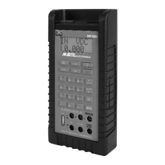
- Page 1 MC1000 Multi-Function Calibrator...
-
Page 2: Table Of Contents
Table of Contents 1. Introduction 1.1 Customer Service ....1 1.2 Standard Equipment ....1 1.3 Safety Information . -
Page 3: Introduction
MC-1000 1. Introduction The MC1000 is designed to be a versatile, easy to use multi-function calibrator with a simple user interface. The following instructions will allow the user to begin simple calibration tasks by learning the basic operation of the keys and their functions. -
Page 4: Safety Information
1.3 Safety information Symbols Used The following table lists the International Electrical Symbols. Some or all of these sym- bols may be used on the instrument or in this manual. Symbol Description AC (Alternating Current) AC-DC Battery CE Complies with European Union Directives Double Insulated Electric Shock... - Page 5 Canadian Standards Association The following definitions apply to the terms “Warning” and “Caution”. • “Warning” identifies conditions and actions that may pose hazards to the user. • “Caution” identifies conditions and actions that may damage the instrument being used. Use the calibrator only as specified in this man- ual, otherwise injury and damage to the calibra- tor may occur.
- Page 6 • Remove test leads from the calibrator before you open the battery door. • Inspect the test leads for damaged insulation or exposed metal. Check test leads continuity. Replace damaged test leads before you use the calibrator. • When using the probes, keep your fingers away from the probe contacts.
- Page 7 Caution To avoid possible damage to calibrator or to equipment under test: • Disconnect the power and discharge all high- voltage capacitors before testing resistance or continuity. • Use the proper jacks, function, and range for your measurement or sourcing application. •...
-
Page 8: Quick Start Instructions
2. Quick Start Instructions A. Key Functions Function Input/Output Toggles the function selected from measurement mode to source mode. V/mA/Hz Selects between volts, mil- liamps, and frequency modes TC/RTD Selects between temperature modes either T/C or RTD. Ohms and mV ranges are also included in these functions. -
Page 9: Setpoints
Press the desired location number and the unit will go to that output. 3. Automated Stepping The MC1000 can auto-step through some or all of the stored setpoints for a given range. The procedure is as follows: a. Press “Shift” followed by auto. - Page 10 To exit press CE or simply enter a new output value. 5. Pressure Module Interface The MC1000 has the capability to inter- face with a family of pressure modules available from Martel. The procedure is as follows: a.
-
Page 12: Connection Diagrams & Instructions
3. Connection Diagrams & Instructions A. Measuring High Voltage AC or DC 1. Select the Voltage Input Mode. Use the “Range” key to select either AC or DC input. 2. Connect the device to be measured as shown in Figure 1. ! WARNING ! When measuring high voltage be sure to use proper connections as shown in Figure 1. -
Page 13: Measuring Current
C. Measuring Current 1. Select the mA input mode. Note: To power the loop while reading current, select the “mAPW” mode. 2. Connect the device under test as shown in Figure 3. 3. Current can either be measured directly in mA or as a percentage such that 4 to 20 mA corresponds to 0 to 100%. -
Page 14: Simulating Current
“Range” key to choose the desired range for the mode you’re operating in. 4. The MC1000 is capable of driving up to ±1 mA on the Voltage and Frequency ranges and is able to handle up to a 3 mA excitation on the Resistance Simulation Range. -
Page 15: Sourcing A Thermocouple Signal
TC wire must be used to achieve an accurate calibration. Figure 7. Note: For best accuracy allow a 10 minute warm-up period after the MC1000 is turned on. H. Measuring Temperature Using a Thermocouple Figure 8. I. Measuring Resistance (RTDs) When measuring resistance (ohms) there are 3 choices when using the MC1000;... - Page 16 2. Make sure the MC1000 is in the Input Mode (Note: that it will indicate 2, 3, or 4W in the upper left corner of the LCD). To set the desired wire configuration use the “Up/Down arrow” keys to toggle through the 2, 3, and 4 wire modes.
-
Page 17: Sourcing Resistance (Rtds)
Refer to Figure 10 for connection information. Figure 10. 4. Serial Communications The MC1000 calibrator is equipped with a RS- 232 serial communications port, which is locat- ed on the top of the case. Note: The user will require a special RS-232 cable to connect the calibrator to a computer or terminal. - Page 18 The MC1000 calibrator can be used with virtually any terminal emulation software. (i.e. Procomm or HyperTerminal) When connected properly, data will be transmit- ted as soon as the calibrator is turned on. The data transmitted to the terminal or computer will mirror that sent to the calibrators LCD display and will be updated approximately every 0.4...
- Page 19 (D.) Stop Bits: (E.) Flow Control: Xon/Xoff Click OK box to accept these entries. 8. Hook up the MC1000 calibrator to the PC uti- lizing the special Martel Electronics RS-232 cable as follows: (A.) Plug the 9 pin connector end of the cable to the appropriate serial port on the computer.
- Page 20 Serial Input Description mA measurement mA source mA loop mA 2W Sim Volts measurement Volts source mV measurement mV source HVAC measure HVDC measure Khz measurement Khz source Hz measurement Hz source CPM measurement CPM source 2-wire measurement (Ohms and RTDs) 3-wire measurement (Ohms and RTDs) 4-wire measurement (Ohms and RTDs) Thermocouple measurement (default Type J) use...
-
Page 21: Maintenance
5. Maintenance A. Power Requirements The MC1000 operates on 4 AA alkaline batteries only. B. Calibration The MC1000 should hold its rated specifica- tions for a minimum of one year. Given this, annual re-calibration is required for best per- formance. -
Page 22: Specifications
4. If a blown fuse is found replace with the enclosed spare fuse. 5. To order more fuses contact Martel Electronics and order part no. 3535039. 6. Specifications Pressure Module Dependent. - Page 23 Range & Accuracy Range Accuracy (% of reading ± counts) V Read (low) 0.000 20.000 0.015% ±2 VDC Read (high) 250.0 0.05% ±2 VAC Read (high) 250.0 0.5% ±2 V Source 0.000 20.000 0.015% ±2 mV Read -10.00 75.00 0.015% ±2 mV Source -10.00 75.00...
- Page 24 Thermocouple Read and Source (All errors included) (cont.) Range Accuracy L Thermocouple -200 0.45°C 900.0 0.4°C U Thermocouple -200 0.7°C 400.0 0.45°C N Thermocouple -200 1.1°C 1300.0 0.6°C mV Read/Source -10.00 75.00 0.015% ±.02 RTD Read and Source Range Accuracy Ni120 (672) -80.0 260.0...
-
Page 25: Warranty
Receiving Department to accept the shipment. Any package not so marked will not be accept- ed and will be returned to the shipper. Martel will not be responsible for damage as a result of poor return packaging. Out of warranty repairs and recalibration will be subject to spe- cific charges. - Page 28 Tel: (603) 434-8179 800-821-0023 Fax: (603) 434-1653 Martel Electronics PO Box 770 1F Commons Drive Londonderry, NH 03053 Rev F 6/07 0219041...
Need help?
Do you have a question about the MC1000 and is the answer not in the manual?
Questions and answers