Table of Contents
Advertisement
Advertisement
Table of Contents

Related Manuals for Hytera E-pole 100


Summary of Contents for Hytera E-pole 100
- Page 1 User Manual Digital WANET Repeater...
- Page 2 Preface Thanks for your favor in our product. This manual provides guidance for you to use the product. To avoid bodily injury and property loss caused by improper operations, please read the Safety Information Booklet before using the product. This manual is applicable to the following product: E-pole Digital WANET Repeater...
- Page 3 Copyright Information Hytera is the trademark or registered trademark of Hytera Communications Corporation Limited (the Company) in PRC and/or other countries or areas. The Company retains the ownership of its trademarks and product names.
- Page 4 0.5 meters away from human body. Compliance with RF Exposure Standards Hytera's radio complies with the following RF energy exposure standards and guidelines: United States Federal Communications Commission, Code of Federal Regulations; 47 CFR §...
- Page 5 Institute of Electrical and Electronic Engineers (IEEE) C95.1:2005 Edition ISEDC Statement This device complies with Innovation, Science and Economic Development Canada Compliance license-exempt RSS standard(s). Operation is subject to the following two conditions: This device may not cause harmful interference. ...
- Page 6 Restrict use warning: AT BE CY CZ DK EE FI FR DE EL HU IE IT LV LT LU MT NL PL PT SK SI ES SE UK BG RO HR ...
-
Page 7: Table Of Contents
Contents 1. Checking Items in the Package ......................1 2. Product Descriptions ......................... 2 3. Installation ............................4 3.1 Installation Requirements ....................... 4 3.2 Pre-Installation Tasks ........................5 3.3 Device Installation ........................... 6 3.4 Cables Installation......................... 11 3.5 Post-installation Check ......................... 12 4. -
Page 8: Checking Items In The Package
1. Checking Items in the Package Please unpack carefully and check if all items listed below are received. If any item is missing or damaged, please contact your dealer. Name Name Mainframe DC Wire AC Wire Owner’s Manual Note All pictures in this manual are for reference only. -
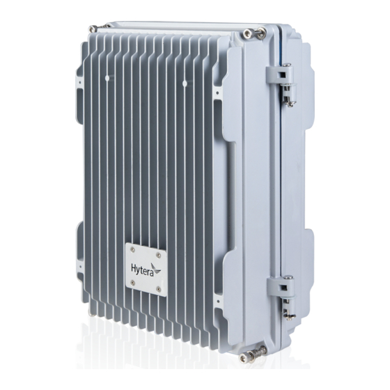
Page 9: Product Descriptions
2. Product Descriptions Part Name Description Used to connect RF antenna for signal transmission and reception. RF Antenna Interface The interface type is the UHF interface. GPS Antenna Connect GPS antenna, and used for transmit and receive SPG signal. Interface Waterproof and Prevent the cavity from forming a vacuum and the lid can not be breathable hole... - Page 10 Part Name Description Interface Bei Dou Interface The reserved interface is not developed for the time being. For E-pole100 debugging. Data Interface Interconnect with center via IP network. The device applies external power supply which supplies AC 100-240V and DC 15V±10%. Power Interface DC power line is connected to DC input, and AC input is connected to AC power line.
-
Page 11: Installation
3. Installation 3.1 Installation Requirements Be sure to follow procedures below for proper installation. Local Regulations and Norms When installing the equipment, please follow the local regulations and norms. Battery Danger Direct contact or indirect contact of high pressure and electricity through wet objects will bring danger of electric shock. -
Page 12: Pre-Installation Tasks
High altitude operators should not throw objects from high altitude to the ground, nor throw objects from the ground to the upper air. We should use strong cables, hanging baskets, elevated cars or cranes to deliver objects. Do a good job of safety protection, wear a helmet and fasten your seat belt correctly. ... -
Page 13: Device Installation
Cross screwdriver, screwdriver, movable spanner, six-angle wrench, cross torque Standard Tools screwdriver, dual wrench, rubber hammer, torque sleeve Protective Antistatic wristband, seat belt, helmet, safety rope, antiskid gloves. Tools Cable Making Crimping pliers, stripping pliers, cutting pliers Tools Instrument Multimeter, tape measure, level ruler Tool Fixed pulley, herringbone ladder, marking pen, impact drill, insulating tape, ribbon Assistant... - Page 14 3.3.2 Pole-Mounted Installation Use two M6×16 bolts to fix the bracket to the rear side of mainframe. Use four M6×16 bolts to fix the pole-mounted bracket to the pole-mounted bracket components.
- Page 15 Mark the position of the pole-mounted bracket components on the pole. Caution The diameter of the holding rod should not exceed 180mm. Use four M10×240 screw suite to fix pole-mounted bracket components and pole-mounted bracket to pole. Adopt the same method to install antenna bracket components, GPS antenna, Bei Dou antenna and RF antenna.
- Page 16 can be less than 200mm. ○ Fix the bracket of mainframe to pole-mounted bracket components with four M6×16 bolts 3.3.3 Wall-mounted Installation Use two M6×16 bolts to fix the bracket to the rear side of the mainframe.
- Page 17 Keep the wall-mounted bracket closely to the wall, level the installation position with a horizontal ruler and mark the point with the marker pen. Punch holes at the location and install the expansion bolt, and use the 4 M6x65 expansion screws to fix the wall-mounted bracket on the wall.
-
Page 18: Cables Installation
3.4 Cables Installation 3.4.1 Cable Laying Requirements Cable placement needs to meet the required layout requirements in order to prevent inter signal interference. Installation Requirement When deploy cables, try to avoid sharp object or wall burr, if impossible, and then use a liner protective cable. -
Page 19: Post-Installation Check
In the process of distribution, if the length of the power line is not enough, the power line should be replaced, and the joint or welding point should not be made with the power line. Playing ring, twisted cable laying phenomenon is strictly prohibited. Protected Ground Wire Laying Requirements ... -
Page 20: Basic Operations
4. Basic Operations 4.1 Power on Connect the product to the external power supply, and the battery indicator glows red constantly. Note In order to make sure that the device can operate for a short time after a sudden power failure. It is suggestible that put the built-in battery switch to ON position. -
Page 21: Troubleshooting
5. Troubleshooting Phenomena Analysis Solution The product Connect the power cord properly and cannot be Abnormal connection of power cord. ensure secure connection. powered on. Problems with transceiver frequency Check the frequency. Please contact band configuration of system. dealer if necessary. Check the interference signal source. -
Page 22: Care And Cleaning
6. Care and Cleaning To guarantee optimal performance as well as a long service life of the product, please follow the tips below. Product Care Do not pierce or scrape the product Keep the product far away from substances that can corrode the circuit. ... -
Page 23: Optional Accessories
7. Optional Accessories Contact your local dealer for the optional accessories of the product. Caution Use the accessories specified by the Company only; otherwise, we shall not be liable for any losses or damages arising out of use of unauthorized accessories. -
Page 24: Scope And Duration Of Warranty
8. Scope and Duration of Warranty Our company promises that if there is any material or manufacturing process defects of the products produced by us from the date of purchase under normal use, operation and maintenance conditions, can enjoy the following provisions of warranty service.
Need help?
Do you have a question about the E-pole 100 and is the answer not in the manual?
Questions and answers