Raypak raytherm p-1826 Installation & Operating Instructions Manual
Commercial swimming pool heater
Hide thumbs
Also See for raytherm p-1826:
- Specifications (4 pages) ,
- Installation and operating instructions manual (38 pages) ,
- Installation & operating instructions manual (36 pages)
Table of Contents
Advertisement
Quick Links
INSTALLATION & OPERATING
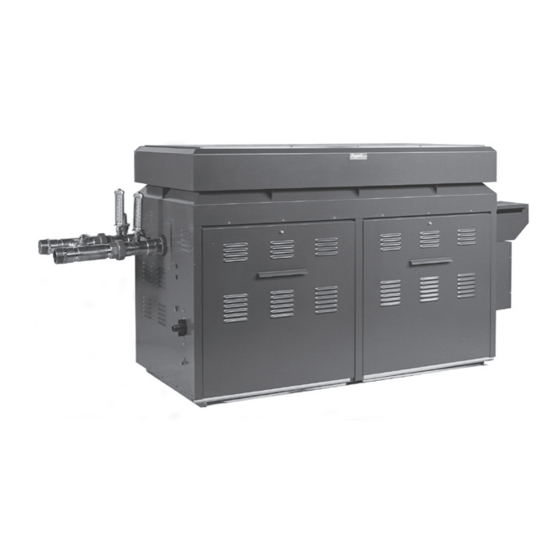
Raytherm
Commercial
Swimming
Pool
Heater
Models
P-926 to P-1826
& P-2100 to P-4001
WARNING: If these instructions are not followed exactly, a fire or explosion may
result causing property damage, personal injury or death.
FOR YOUR SAFETY: Do not store or use gasoline or other flammable vapors and
liquids or other combustible materials in the vicinity of this or any other appliance.
To do so may result in an explosion or fire.
WHAT TO DO IF YOU SMELL GAS:
• Do not try to light any appliance.
• Do not touch any electrical switch; do not use any phone in your building.
• Immediately call your gas supplier from a neighbor's phone. Follow the gas
supplier's instructions.
• If you cannot reach your gas supplier, call the fire department.
Installation and service must be performed by a qualified installer, service agency or
the gas supplier.
This manual should be maintained in legible condition and kept adjacent to the heater or in another safe place for
future reference.
CATALOG NO. 6200.51T
INSTRUCTIONS
®
Effective: 05-15-18
Replaces: 07-01-16
P/N 240251 Rev. 21
Advertisement
Table of Contents


Need help?
Do you have a question about the raytherm p-1826 and is the answer not in the manual?
Questions and answers