Table of Contents
Advertisement
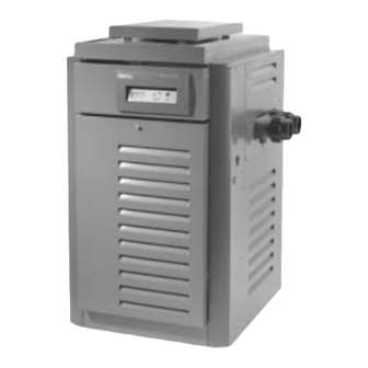
INSTALLATION
AND OPERATING
INSTRUCTIONS
Models
P-R185A to P-R405A
C-R185A to P-R405A
Low NOx
P-R185AL to P-R405AL
C-R185AL to C-R405AL
RP2100
SWIMMING POOL
and
SPA HEATER
WARNING: If the information in these instructions are not followed exactly, a fire or
explosion may result causing property damage, personal injury or death.
— Do not store or use gasoline or other flammable vapors and liquids in the vicinity of
this or any other appliance.
— WHAT TO DO IF YOU SMELL GAS
•
Do not try to light any appliance.
•
Do not touch any electrical switch; do not use any phone in your building.
•
Immediately call your gas supplier from a neighbor's phone. Follow the gas
supplier's instructions.
•
If you cannot reach your gas supplier, call the fire department.
— Installation and service must be performed by a qualified installer, service agency or
the gas supplier.
This manual should be maintained in legible condition and kept adjacent to the
heater or kept in a safe place for future reference.
CATALOG NO. 6000.52-Z
Effective:
11-01-01
Replaces:
08-01-01
®
Part No. 240612
Advertisement
Table of Contents

Subscribe to Our Youtube Channel
Related Manuals for Raypak P-R185A to P-R405A, C-R185A to P-R405A, P-R185AL to P-R405AL, C-R185AL to C-R405AL, RP2100


Summary of Contents for Raypak P-R185A to P-R405A, C-R185A to P-R405A, P-R185AL to P-R405AL, C-R185AL to C-R405AL, RP2100
- Page 1 INSTALLATION AND OPERATING INSTRUCTIONS Models P-R185A to P-R405A C-R185A to P-R405A Low NOx P-R185AL to P-R405AL C-R185AL to C-R405AL RP2100 SWIMMING POOL SPA HEATER WARNING: If the information in these instructions are not followed exactly, a fire or explosion may result causing property damage, personal injury or death. —...
- Page 2 TO WHOM IT MAY CONCERN: The new Raypak series RP2100 pool heaters have been designed to eliminate the need for conventional heat sinks (high temperature piping). The initial connection to the heater is made with a 2" PVC union adapter to which PVC may then be connected with appropriate cement.
-
Page 3: Table Of Contents
PART ONE OWNER'S OPERATING INSTRUCTIONS SECTION 1 START-UP PROCEDURES Before Start-Up Lighting Instructions & Shut-Off Procedure (Manually Lighted Pilot MV) Operating Instruction & Shut-Off Procedures (Automatically Lighted Pilot IID) After Start-Up SECTION 2 CAUTION SECTION 3 MAINTENANCE & CARE PROCEDURE Pool &... -
Page 4: Part One
PART ONE - OWNER'S OPERATING INSTRUCTIONS FOR YOUR SAFETY - READ BEFORE OPERATING WARNING: IF YOU DO NOT FOLLOW THESE INSTRUCTIONS EXACTLY, A FIRE OR EXPLOSION MAY RESULT, CAUSING PROPERTY DAMAGE, PERSONAL INJURY OR LOSS OF LIFE. SECTION 1 / START-UP PROCEDURES Your Raypak Pool/Spa heater has been designed for years of safe and reliable pool/spa water heating. -
Page 5: Lighting Instructions
confined areas, extra care should be exercised when lighting propane heaters. LIGHTING INSTRUCTIONS AND SHUT-OFF PROCEDURES This appliance has a pilot that must be lighted by hand. When lighting the pilot, follow these instructions exactly. BEFORE LIGHTING smell all around the appliance area for gas. -
Page 6: (Automatically Lighted Pilot Iid)
CAUTION: Propane gas is heavier than air and will settle on the ground. Since propane can accumulate in confined areas, extra care should be exercised when lighting propane heaters. OPERATING INSTRUCTIONS AND SHUT-OFF PROCEDURES ELECTRONIC IGNITIONS SYSTEMS This appliance is equipped with an ignition device which automatically lights the pilot. -
Page 7: Water Pressure Switch
AFTER START-UP Feel the inlet and outlet pipes. Outlet pipe should be only slightly warmer than the inlet. It should not be hot. WARNING: Should overheating occur or the gas supply fail to shut off, turn off the manual gas control to the appliance. -
Page 8: Pool & Spa Water Chemistry
4. Make visual check of the burner and pilot flame. Flame pattern on the main burner and pilot is indi- cated in the previous illustration. Yellow flame means restriction of the air openings. Lifting or blowing flame indicates high gas pressure. Low flame means low gas pressure. -
Page 9: Winterizing The Pool & Spa Heater
WINTERIZING THE POOL & SPA HEATER When heaters installed outdoors in freezing climate areas are to be shut down for the winter, observe the following step-by-step procedure: 1. Turn off gas valve, manual gas valve, and electrical supply to the heater. 2. -
Page 10: Installation Instructions
SECTION 3 / INSTALLATION INSTRUCTIONS IMPORTANT NOTICE These instructions are intended for the use of quali- fied personnel only, specifically trained and experienced in the installation of this type of heating equipment and related system components. Installation and service personnel may be required by some states to be licensed. If your state is such, be sure your contractor bears the appropriate license. - Page 11 HEATER WITH OUTDOOR STACKLESS TOP Outdoor Top Heaters must not be installed under an overhang of less than three (3) feet from the top of the heater. Three (3) sides must be open in the area under the overhang. Roof water drainage must be diverted away from the heaters installed under overhangs with the use of gutters.
-
Page 12: Indoor Heater
INDOOR HEATER The design is also certified for indoor installation when equipped with the approved draft hood. For Canada, indoor installation is restricted to an enclosure that is not occupied and does not directly communicate with occupied area. Refer to the latest edition of CAN/CGA-B149.1 and B149.2 for specific requirements. -
Page 13: Specifications And Dimensions
SPECIFICATIONS AND DIMENSIONS *Designation for Propane is "EP", Natural gas is "EN". Prefix "C" is for Cast Iron (ASME) Headers; "P" is for Plastic (Capron) Headers. Above input ratings are per A.G.A. specifications. Reduce input 4% for each 1000 ft. above sea level when installed above 2000 ft. -
Page 14: Vent Piping
VENT PIPING WARNING: Indoor boilers require a drafthood that must be connected to a vent pipe and properly vented to the outside. Failure to follow this procedure can cause fire or fatal carbon monoxide poisoning. Vent piping the same size as the draft hood outlet is recommended, however, when the total vent height is at least ten (10) feet (draft hood relief opening to vent terminal), the vent pipe size may be reduced as speci-... -
Page 15: Plumbing For Water Connections
NOTE: Do not use teflon tape on gas line pipe thread. A flexible sealant is recommended. A minimum of 7" W.C. and a maximum of 14" W.C. upstream pressure under load, and no load conditions must be provided for natural gas or a minimum of 12" W.C. - Page 16 Plumbing from the heater back to the pool must not have any valves or restriction that could prevent flow when the pump is operating. CAUTION: A source of additional heated water, i.e. solar systems, must be connected to the heater outlet pipe. If this is connected to the heater inlet, incorrect pool water temperature readings will be displayed on the heater control panel.
-
Page 17: Pressure Relief Valve Installation
PRESSURE RELIEF VALVE INSTALLATION To conform to local building codes, it may be necessary to install a pressure relief valve. A 3/4" pressure relief valve having a capacity equal to BTU/HR output of the model to be installed is recommended for this appliance. -
Page 18: Rp2100 Heat Exchanger Reversal Procedure
RP2100+ Heat Exchanger Reversal Procedure 1. Remove right and left side access panels (Figure 1). 2. Disconnect wires at high limit, AGS (automatic gas shutoff), and pressure switch on the inlet/outlet header (Figure 2). 3. Electronic Ignition Heaters: Remove the thermostat temperature sensor by loosening the compression- fitting nut (Figure 3). - Page 19 JACO FITTING Fig. #3 BULB & CLIP Fig. #4 RE-INSTALLED IN/OUT HEADER ON OPPOSITE SIDE. Fig. #5...
-
Page 20: Electrical Wiring
ELECTRICAL WIRING NOTE: If it is necessary to replace any of the original wiring, it must be replaced with 105° C wire or its equivalent, and /or 150° C wire or its equivalent as originally built. MILLIVOLT SYSTEM The Millivolt System residential heater is equipped with a self-generating electrical system in which the electric current is provided by means of a pilot genera- tor. -
Page 21: Wiring Diagram Key
For 120 V input power to the unit, connect the black wire to the “L1” or hot leg of the power supply. Connect the white wire to the “L2” or neutral leg of the power supply. Attach the wire nut to the red wire. There should be no connection to the red wire for 120V operation. - Page 22 WIRING DIAGRAM - IID UNITS (atmospheric)
- Page 23 WIRING DIAGRAM - IID UNITS (Low NOx)
-
Page 24: Section 4 / Servicing Instructions
SECTION 4 / SERVICING INSTRUCTIONS GENERAL LOCATION OF CONTROLS Drain Plug (Located in Return Header) Ignition Control (IID) Digital Thermostat Module Roll-Out Switch Gas Valve Pilot CONTROL PANEL REMOVAL 1. Remove (4) screws from sides of control panel. 2. Rotate control panel down until panel stops. Do not force. -
Page 25: Electronic Controls
ELECTRONIC CONTROLS The pool heater thermostat on the upper front panel of the heater controls the pool/spa water temperature. This control center contains a mode button, up and down temperature adjustment buttons, and a LCD display. The MODE button functions as a means to turn the heater off or on in either the pool or spa temperature setting. -
Page 26: Remote Control Installation
RP2100 REMOTE CONTROL INSTALLATION CAUTION: Before installing remote controls to the RP2100 Digital Heater, read the following: The Raypak RP 2100 Digital Heater is remote ready in most cases. The digital liquid crystal (LCD) display shows the actual pool temperature, operating status, and service codes (See examples below). -
Page 27: Pressure Switch Adjustment
PRESSURE SWITCH The pressure switch, or heater actuator, insures that the heater operates only when the filter pump is in operation. It is located on the inlet/outlet header. It is factory set at 1.75 PSI for deck level installations. When the heater is located below the level of the spa or pool, it may be necessary to reset the pressure switch to compensate for the no-flow static head. -
Page 28: Burner Drawer Removal
BURNER DRAWER REMOVAL 1. Shut off main electrical power switch to heater. 2. Shut off gas upstream of heater. 3. Remove front door. 4. Disconnect gas line from gas valve. 5. Remove (2) screws that mount burner tray to unit, and (2) screws that secure gas valve to jacket. -
Page 29: Tube Cleaning Procedure
Extension Pieces (2) TUBE CLEANING PROCEDURE Establish a regular inspection schedule, frequency depending on local water condition and severity of service. Do not let the tubes clog up solidly. Clean out deposits over 1/16" in thickness. The heater may be cleaned from the return header side, without breaking pipe connections. -
Page 30: Operation
ADDENDA: LOW NOx POOL HEATERS The Raypak Low Nox Pool Heaters are certified and tested under the ANSI Z21.56.CSA 4.7 Standards for gas fired pool heaters. The heater should be installed to meet all local codes, the latest editions of the National Fuel Gas Code Z223.1 and the National Electrical Code, ANSI/NFPA 70. -
Page 31: Pilot Removal
ADDENDA: LOW NOX HEATERS LOW NOx BURNER TRAY ASSEMBLY BURNER DRAWER REMOVAL 1. Shut off main electrical power switch to heater. 2. Shut off gas upstream of heater. 3. Remove front door. 4. Disconnect gas line from gas valve. 5. Remove (2) screws that mount burner tray to the base of the unit, and (2) screws that secure gas valve to jacket. -
Page 32: Section 5 / Trouble Shooting Guide
SECTION 5 / TROUBLE SHOOTING GUIDE MECHANICAL (FOR QUALIFIED SERVICE PERSONNEL ONLY) IMPORTANT NOTICE These instructions are primarily intended for the use of qualified personnel specifically trained and experienced in the installation of this type of heating equipment and related system components. Installation and service personnel may be required by some states to be licensed. - Page 33 ELECTRICAL ( STANDING PILOT MILLIVOLT) ELECTRICAL CHECK WITH MV GAS VALVE CAUTION: For qualified service personnel only. Filter must be on with adequate water flow through heater. Gas valve must be "ON" position. Thermostat set higher than pool water temperature. Jumpers are for temporary check only.
-
Page 34: Warning High Voltage
ELECTRICAL (ELECTRONIC IGNITION IID) TROUBLESHOOTING HONEYWELL S8600 START TURN GAS SUPPLY OFF. TURN THERMOSTAT (CONTROLLER) TO CALL FOR HEAT POWER TO MODULE (24 V NOMINAL) SPARK ACROSS IGNITER/SENSOR GAP TURN GAS SUPPLY ON PILOT BURNER LIGHTS? SPARK STOPS WHEN PILOT IS LIT? MAIN BURNER LIGHTS? SYSTEM RUNS UNTIL CALL FOR HEAT ENDS? -
Page 36: Section 6/Replacement Parts List
SECTION 6/REPLACEMENT PARTS LIST NOTE: To supply the correct part it is important that you state the model number, serial number and type of gas when applicable. Any part returned for replacement under standard company warranties must be properly tagged with RAYPAK return parts tag, completely filled in with the heater serial number, model number, etc., and shipped to the Company freight prepaid. - Page 38 Low NOx BURNER TRAY PILOT ASSEMBLIES 17-P Honeywell IID Atmospheric units for units produced prior to 06/01/2000 15-P 13-P 16-P Honeywell MV 14-P 16-P Honeywell IID Low NOx and Atmospheric units Fig. #8124 for units produced after to 06/01/2000 Use KIT Number 008155F for Low NOx units Use KIT Number 002003F for Atmospheric units Fig.
-
Page 42: Warranty
RAYPAK RESIDENTIAL SWIMMING POOL AND SPA HEATERS GAS MODELS 185, 265, 335 & 405 MILLIVOLT GENERAL Raypak, Inc. warrants that the cabinet, burner tray (minus controls) and refractory will be free from defects in materials and workmanship under normal use and service for a period of FIVE YEARS FROM THE DATE OF ORIGINAL PURCHASE FOR A SINGLE FAMILY RESIDENCE (ONE YEAR IF OTHER THAN FOR SINGLE FAMILY RESIDENCE USE). - Page 43 www.raypak.com Raypak, Inc., 2151 Eastman Avenue, Oxnard, CA 93030 (805) 278-5300 FAX (800) 872-9725 Raypak Canada LTD, 2805 Slough Street, Mississauga, Ontario, Canada L4T 1G2 (905) 677-7999 FAX (905) 677-8036 Raypak Australia Pty. Ltd, 7 Geddes St., Mulgrave, Victoria, Australia 3170 (6139) 560 4944 FAX (6139) 560 4974 Litho in U.S.A.
Need help?
Do you have a question about the P-R185A to P-R405A, C-R185A to P-R405A, P-R185AL to P-R405AL, C-R185AL to C-R405AL, RP2100 and is the answer not in the manual?
Questions and answers