Table of Contents

Related Manuals for BUSCH COBRA ATEX NC 2500 B


Summary of Contents for BUSCH COBRA ATEX NC 2500 B
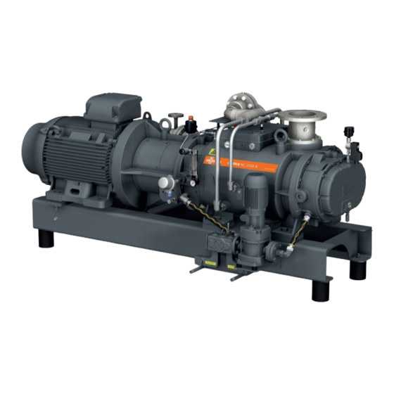
- Page 1 Instruction Manual COBRA ATEX Dry Screw Vacuum Pumps NC 2500 B (water-cooled version) Ateliers Busch S.A. Zone industrielle, 2906 Chevenez Switzerland 0870569470/-0003_en / Original instructions / Modifications reserved 07/07/2020...
-
Page 2: Table Of Contents
Table of Contents Table of Contents 1 Safety ............................4 2 Product Description ........................5 2.1 Operating Principle ......................6 2.2 Application........................6 2.3 Start Controls ........................6 2.4 Standard Features ......................7 2.4.1 Water Cooling ....................... 7 2.4.2 Cooling Gas Recirculation ..................7 2.4.3 Resistance Thermometer (Cooling Liquid).............. - Page 3 Table of Contents 6.4 Restart Procedure ......................29 7 Maintenance..........................30 7.1 Maintenance Schedule ..................... 31 7.2 Oil Level Inspection ......................31 7.3 Cooling Liquid Level Inspection ..................32 7.4 Oil Change........................32 7.5 Cooling Liquid Change..................... 35 7.6 Calibration Procedure of the Electrical Devices ..............39 7.6.1 Procedure A ......................
-
Page 4: Safety
Safety Prior to handling the machine, this instruction manual should be read and understood. If anything needs to be clarified, please contact your Busch representative. Read this manual carefully before use and keep for future reference. This instruction manual remains valid as long as the customer does not change anything on the product. -
Page 5: Product Description
Product Description | 2 Product Description TSA+/0101 CLV2 PSA+/0301 TV CLD CLV1 CWOGC CWIGC TSA+/0102 Barrier gas system Cooling liquid drain plug* Cooling liquid fill plug Cooling liquid sight glass Cooling liquid pump CLV1 Cooling liquid vent plug (cooling liquid pump) CLV2 Cooling liquid vent plug (machine) -
Page 6: Operating Principle
No ATEX zone Conveying of other media leads to an increased thermal and/or mechanical load on the machine and is permissible only after a consultation with Busch. The machine is capable of maintaining ultimate pressure, see Technical Data [► 44]. The machine is suitable for continuous operation. -
Page 7: Standard Features
Product Description | 2 2.4 Standard Features 2.4.1 Water Cooling The machine is cooled by a cooling liquid circuit in the cylinder cover and cylinder. The cooling liquid pump (CLP) allows a recirculating flow in the cooling liquid chamber. The motor of the cooling liquid pump must be electrically connected, see Electrical Con- nection of the Cooling Liquid Pump [► 22] The cooling liquid is cooled by a plate heat exchanger (PHE) which must be connected to the water main. -
Page 8: Optional Accessories
2 | Product Description 2.5 Optional Accessories 2.5.1 Silencer A silencer at the discharge connection (OUT) can be provided to reduce the exhaust gas noise. 2.5.2 Mechanical Seals The sealing systems can be equipped with mechanical seals. The following variants are possible: –... -
Page 9: List Of Mandatory Atex Accessories
Product Description | 2 The limit values of each accessory are defined in the wiring diagram chapters, see Elec- trical Connection of the Monitoring Devices [► 23]. To have more details about the monitoring procedure, see Flowchart [► 26]. 2.7.1 List of Mandatory ATEX Accessories The following list indicates the mandatory accessories according to the ATEX classifica- tion of the machine. -
Page 10: Transport
3 | Transport Transport WARNING Suspended load. Risk of severe injury! • Do not walk, stand or work under suspended loads. WARNING Lifting the machine using the motor eye bolt. Risk of severe injury! • Do not lift the machine using the eye bolt fitted to the motor. Only lift the machine as shown. -
Page 11: Storage
Storage | 4 Transport with a Forklift Handling access must be from the underneath of the base frame • Check the machine for transport damage. If the machine is secured to a base plate: • Remove the machine from the base plate. Storage •... -
Page 12: Installation
• Check the cooling liquid level, see Cooling Liquid Level Inspection [► 32]. If the machine is installed at an altitude greater than 1000 meters above sea level: • Contact your Busch representative, the motor should be derated or the ambient temperature limited. -
Page 13: Connecting Lines / Pipes
Connection size(s): – DN150 PN16 or 6’’ ASME B16.5 Class 150 If the machine is used as part of a vacuum system: • Busch recommends the installation of an isolation valve in order to prevent the machine from turning backwards. 0870569470_NC2500B_Ex_WCV_-0003_IM_en... -
Page 14: Discharge Connection
5 | Installation 5.2.2 Discharge Connection Connection size(s): At the machine discharge connection: – DN100 PN16 or 4’’ ASME B16.5 Class 150 At the silencer (SI) discharge connection: – DN100 ISO-K, DIN 28404 • Make sure that the discharged gas will flow without obstruction. Do not shut off or throttle the discharge line or use it as a pressurised air source. -
Page 15: Cooling Gas Recirculation
Installation | 5 Free chloride mg/l < 0.3 Materials in contact with the cooling water Stainless steel NOTE Water hardness unit conversion. 1 mg/l (ppm) = 0.056 °dh (german degree) = 0.07 °e (english degree) = 0.1 °fH (french degree) 5.2.4 Cooling Gas Recirculation CWOGC CWIGC... -
Page 16: Barrier Gas System Connection
5 | Installation NOTE Water hardness unit conversion. 1 mg/l (ppm) = 0.056 °dh (german degree) = 0.07 °e (english degree) = 0.1 °fH (french degree) 5.2.5 Barrier Gas System Connection Without nitrogen panel Barrier gas connection Flow meter Flow regulator Manometer Pressure regulating valve •... -
Page 17: Filling Oil
Risk of premature failure! Loss of efficiency! • Only use an oil type which has previously been approved and recommended by Busch. For oil type and oil capacity see Technical Data [► 44] and Oil [► 44]. Oil filling at the motor side... - Page 18 Last oil change __ / __ / ____ Oil type see nameplate Change interval see instruction manual If there is no sticker (part no. 0565 568 959) on the machine: • Order it from your Busch representative. 18 / 48 0870569470_NC2500B_Ex_WCV_-0003_IM_en...
-
Page 19: Filling Cooling Liquid
Installation | 5 5.4 Filling Cooling Liquid For cooling liquid type and cooling liquid capacity see Technical Data [► 44] and Cooling Liquid [► 44]. Cooling liquid filling Cooling liquid vent plug (CLV1) Fill up to the top of the vent orifice (CLV1) Resume cooling liquid filling 0870569470_NC2500B_Ex_WCV_-0003_IM_en 19 / 48... -
Page 20: Fitting The Coupling
• Provide an overload protection according to EN 60204-1 for the motor. • Make sure that the motor of the machine will not be affected by electric or electro- magnetic disturbance from the mains; if necessary seek advice from Busch. • Connect the protective earth conductor. -
Page 21: Wiring Diagram Three-Phase Motor (Pump Drive)
Installation | 5 NOTICE The admissible motor nominal speed exceeds the recommendation. Risk of damage to the machine! • Check the admissible motor nominal speed (n ) on the nameplate of the machine (NP). • Make sure to comply with it. •... -
Page 22: Electrical Connection Of The Cooling Liquid Pump
5 | Installation • Watch the fan wheel of the motor and determine the direction of rotation just before the fan wheel stops. If the rotation of the motor must be changed: • Switch any two of the motor phase wires. 5.7 Electrical Connection of the Cooling Liquid Pump DANGER Live wires. -
Page 23: Electrical Connection Of The Monitoring Devices
Installation | 5 5.8 Electrical Connection of the Monitoring Devices NOTE In order to prevent potential nuisance alarms, Busch allows that the control system is configured with a time delay of 2 seconds. NOTE The accessories below are considered as standard. -
Page 24: Wiring Diagram Pressure Transmitter
• Always use the mandatory monitoring sensors. WARNING Another sensor type. Risk of severe injury! Risk of explosion! • Only the following sensor type(s) has (have) been approved by Busch and it (they) cannot be replaced by another one. 24 / 48 0870569470_NC2500B_Ex_WCV_-0003_IM_en... - Page 25 Installation | 5 NOTE The wiring diagram is separately provided (specific sheet) with the machine. 0870569470_NC2500B_Ex_WCV_-0003_IM_en 25 / 48...
-
Page 26: Flowchart
5 | Installation 5.9 Flowchart The machine safety depends on the monitoring accessories sequencing according to the following flowchart. Start Warning: T < T warning? T < T trip? High cooling temperature! Warning: T < T warning? T < T trip? High gas temperature ! Warning: P <... -
Page 27: Commissioning
Commissioning | 6 Commissioning WARNING The machine is still running after a monitoring device has tripped. Risk of severe injury! Risk of explosion! • Follow the Trip Procedure [► 29]. NOTICE The machine can be shipped without oil. Operation without oil will ruin the machine in short time! •... -
Page 28: Recommendations On Operation
6 | Commissioning • Adjust the barrier gas pressure and volume flow. • Switch on the machine. • Make sure that the maximum permissible number of starts does not exceed 6 starts per hour. Those starts should be spread within the hour. •... -
Page 29: Trip Procedure
• Do not restart the machine before finding out the source of dysfunction. Once the problem identified fix it, see Troubleshooting [► 42]. • In case of doubt, please contact your Busch representative. 6.4 Restart Procedure Prior to restart the system, ascertain the reason for the emergency stop. -
Page 30: Maintenance
Risk of injuries! Risk of premature failure and loss of efficiency! • Respect the maintenance intervals or ask your Busch representative for service. • Shut down the machine and lock against inadvertent start up. • Turn off the water supply. -
Page 31: Maintenance Schedule
• Check the cooling liquid level, see Cooling Liquid Level Inspection [► 32]. • Check the machine for oil leaks - in case of leaks have the machine repaired (contact Busch). Yearly • Carry out a visual inspection and clean the machine from dust and dirt. -
Page 32: Cooling Liquid Level Inspection
NOTICE Use of an inappropriate oil. Risk of premature failure! Loss of efficiency! • Only use an oil type which has previously been approved and recommended by Busch. Oil draining at the motor side Drain pan 32 / 48 0870569470_NC2500B_Ex_WCV_-0003_IM_en... - Page 33 Maintenance | 7 Magnetic plug Drain pan Cleaning cloth Oil draining at the suction side Magnetic plug Drain pan Cleaning cloth 0870569470_NC2500B_Ex_WCV_-0003_IM_en 33 / 48...
- Page 34 7 | Maintenance For oil type and oil capacity see Technical Data [► 44] and Oil [► 44]. Oil filling at the motor side Check oil level Oil filling at the suction side Check oil level When the oil filling is achieved: •...
-
Page 35: Cooling Liquid Change
Oil type see nameplate Change interval see instruction manual If there is no sticker (part no. 0565 568 959) on the machine: • Order it from your Busch representative. 7.5 Cooling Liquid Change NOTICE Cooling liquid draining. Risk of substantial cooling liquid flow! •... - Page 36 7 | Maintenance Additional cooling liquid draining points Bottom view of the machine 36 / 48 0870569470_NC2500B_Ex_WCV_-0003_IM_en...
- Page 37 Maintenance | 7 Additional cooling liquid draining point 1 Drain pan Additional cooling liquid draining point 2 Drain pan 0870569470_NC2500B_Ex_WCV_-0003_IM_en 37 / 48...
- Page 38 7 | Maintenance Additional cooling liquid draining point 3 Bottom view of the machine Drain pan For cooling liquid type and cooling liquid capacity see Technical Data [► 44] and Cooling Liquid [► 44]. Cooling liquid filling Cooling liquid vent plug (CLV1) Fill up to the top of the vent orifice (CLV1) 38 / 48...
-
Page 39: Calibration Procedure Of The Electrical Devices
• Reassemble the pressure transmitter on the machine. 7.6.3 Procedure D • Remove the vibration sensor from the machine. • Control it with a calibration system or send it to: Ateliers Busch S.A. Zone Industrielle CH-2906 Chevenez • Reassemble the vibration sensor on the machine (8Nm). -
Page 40: Overhaul
• Decontaminate the machine as much as possible and state the contamination status in a ‘Declaration of Contamination’. Busch will only accept machines that come with a completely filled in and legally binding signed ‘Declaration of Contamination’ (form downloadable from www.buschvacuum.com). -
Page 41: Spare Parts
• The exclusive use of Busch genuine spare parts and consumables is recommended for the correct functioning of the machine and to validate the warranty. There is no standard spare parts kits available for this product, if you require Busch gen- uine parts: •... -
Page 42: Troubleshooting
Busch). Solid foreign matter has • Remove the solid foreign entered the machine. matter or repair the ma- chine (contact Busch). • Install an inlet filter if ne- cessary. The resistance thermometer • Let the machine cool (TSA) reached the switch down. - Page 43 • Seek advice from your local Busch representa- tive. Process deposits on the • Flush the machine. pumping components If an inlet screen or an inlet •...
-
Page 44: Technical Data
12 | Technical Data 12 Technical Data NC 2500 B Pumping speed m³/h 2000 / 2500 (50Hz / 60Hz) Ultimate pressure hPa (mbar) abs. ≤1.0 (50Hz / 60Hz) Nominal motor rating 55 / 63 (50Hz / 60Hz) Nominal motor speed 3000 / 3600 (50Hz / 60Hz) Noise level (EN ISO 2151) -
Page 45: Eu Declaration Of Conformity
This Declaration of Conformity and the CE-mark affixed to the nameplate are valid for the machine within the Busch scope of delivery. This Declaration of Conformity is issued under the sole responsibility of the manufacturer. When this machine is integrated into a superordinate machinery the manufacturer of the superordinate machinery (this can be the operating company, too) must conduct the conformity assessment process for the superordinate machine or plant, issue the Declaration of Conformity for it and affix the CE-mark. - Page 46 Note...
- Page 47 Note...
- Page 48 Chile Israel Portugal United Arab Emirates info@busch.cl service_sales@busch.co.il busch@busch.pt sales@busch.ae China Italy Romania United Kingdom info@busch-china.com info@busch.it office@buschromania.ro sales@busch.co.uk Colombia Japan Russia info@buschvacuum.co info@busch.co.jp info@busch.ru info@buschusa.com Czech Republic Korea Singapore info@buschvacuum.cz busch@busch.co.kr sales@busch.com.sg www.buschvacuum.com 0870569470/-0003_en / © Ateliers Busch S.A.
Need help?
Do you have a question about the COBRA ATEX NC 2500 B and is the answer not in the manual?
Questions and answers