Jungheinrich EFG 110k Operating Instructions Manual
Hide thumbs
Also See for EFG 110k:
- Operating instructions manual (188 pages) ,
- Operating instructions manual (6 pages)
Table of Contents
Advertisement
Advertisement
Table of Contents

Related Manuals for Jungheinrich EFG 110k


Summary of Contents for Jungheinrich EFG 110k
- Page 1 EFG 110k/110/113/115 01.04- Operating instructions 52020290 03.10...
- Page 2 Used to indicate standard equipment. Used to indicate optional equipment. Our trucks are subject to ongoing development. Jungheinrich reserves the right to alter the design, equipment and technical features of the truck. No guarantee of particular features of the truck should therefore be inferred from the present operating instructions.
-
Page 4: Table Of Contents
Table of contents Correct use and application of the truck Truck description Description of application ..............B 1 Description of assemblies and functions ..........B 2 Description of truck ................B 3 Technical data of standard version ............. B 4 Types of hoist frame ................ - Page 5 Operation Safety regulations governing the operation of the fork lift truck ..E 1 Description of the operating controls and indicators ......E 2 Auxiliary electrical system o ............... E 5 2.1.1 Dashboard switches o ............... E 5 2.1.2 Operating console switches o ............E 5 Multi function display t ..............
- Page 6 Operational safety and environmental protection ........ F 1 Safety regulations applicable to truck maintenance ......F 1 Servicing and inspection ..............F 3 Maintenance check list for EFG 110k/110/113/115 ......F 4 Lubrication plan for EFG 110k/110/113/115 ........F 6 Fuels, coolants and lubricants ............. F 7 Description of servicing operations .............
- Page 8 Appendix JH Traction Battery Operating Instructions These operating instructions apply only to Jungheinrich battery models. If using another brand, refer to the manufacturer's operating instructions. If using a battery with closed EPzV and EPzV ironclad plates, this must first be...
-
Page 10: A Correct Use And Application Of The Truck
A Correct use and application of the truck The “Guidelines for the Correct Use and Application of Industrial Trucks” (VDMA) are included in the scope of delivery for this truck. The guidelines are part of these oper- ating instructions and must always be heeded. National regulations are fully applica- ble. -
Page 12: B Truck Description
Also closed-ground pallets can be picked up. Vehicle types and maximum load capacity: Model max. load capacity *) Load centre EFG 110k 1,000 kg 500 mm EFG 110 1,000 kg 500 mm... -
Page 13: Description Of Assemblies And Functions
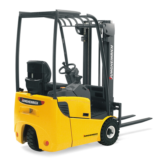
Description of assemblies and functions Item Designation t Steering system t Hoist frame t Drive axle t Batteries t Fork carrier t Counterweight t Driver's seat t Overhead guard... -
Page 14: Description Of Truck
Description of truck Steering (1): Low steering forces of 15 N and an ideal ratio of 5 steering wheel rev- olutions for a steering angle of 180°. A hydraulic steering motor drives the steering axle via a gear wheel pair. Efficient energy usage due to the implemented dynamic load sensing system. -
Page 15: Technical Data Of Standard Version
Technical data of standard version (all dimensions in mm) Designation EFG 110k EFG 110 EFG 113 EFG 115 a/2 Safety distance Height with hoist frame 2,000 2,000 2,000 2,000 retracted Free lift Length of lift 3,000 3,000 3,000 3,000 Height with hoist frame... -
Page 17: Types Of Hoist Frame
Types of hoist frame (all dimensions in mm) Lifting mast table EFG 110k/110/113/115 VDI 3596 Overall height, Overall height, extended Lift Free lift Designation retracted h height 2,300 1,650 2,850 3,000 2,000 3,550 3,100 2,050 3,650 3,300 2,150 3,850 3,600... -
Page 19: Performance Data
Performance data Designation EFG 110k EFG 110 EFG 113 EFG 115 Q Load capacity 1,000 1,000 1,250 1,500 (at c = 500 mm) *) c Load centre distance Driving speed with / 12/12.5 12/12.5 12/12.5 12/12.5 km/h without load Lifting speed 0.28/0.50... -
Page 20: Weights
180 / 70 - 8; Diagonal, 16PR; 10bar 18 x 7-8 Tyre size, rear Rubber 18 x 6 x 12 1/8“ Pneumatic 180 / 70 - 8; Diagonal, 16PR; 10bar Permissible tyres: See chapter F “Forklift Truck Maintenance”. For any queries please contact your Jungheinrich customer adviser. -
Page 21: En Standards
EN standards Continuous sound level: 63 dB(A) according to EN 12053 as stipulated in ISO 4871 The continuous sound level is a value averaged according to standard regulations, taking the sound pressure level into account when driving, lifting and idling. The sound pressure level is measured at the ear. -
Page 22: Location Of Instruction Labels And Identification Plates
Location of instruction labels and identification plates Warning and information labels, such as capacity diagrams, attachment points and identification plates, must be readable at all times or be replaced, if necessary. (mm) Q (kg) D (mm) (mm) Q (kg) D (mm) Item Designation Label Fit locations... -
Page 23: Truck Identification Plate
Truck identification plate Item Designation Item Designation Type Manufacturer Serial No. Min./max. battery weight in kg Rated capacity in kg Drive power in kW Battery: Voltage V Load centre distance in mm Empty weight without battery in kg Year of manufacture Manufacturer logo Option In the event of queries relating to the truck or spare part orders, please state the serial... -
Page 24: Capacity Label Fork Tines (Basic Device)
Capacity label Fork tines (basic device) The fork arm load diagram indicates the carrying capacity Q of the truck in kg. The maximum load capacity at different load centers D is given in a diagram (in mm). Capacity label Attachment The attachment load diagram indicates the carrying capacity Q of the truck in connec- tion with the respective attachment in kg. - Page 25 B 14...
-
Page 26: C Transportation And Commissioning
C Transportation and commissioning Transportation by crane Only use lifting equipment with sufficient carrying capacity (loading weight = own weight + battery weight; see identification plate of the truck). – Park the truck and render it safe (refer to chapter E). –... - Page 27 To transport the fork lift truck without lifting mast perform lashing across the overhead guard front. Lashing and wedging without lifting mast Approximate centre of gravity...
-
Page 28: First Commissioning
First commissioning Commisioning and instruction of the driver must only be carried out by personnel with appropriate training. If several trucks are delivered it must be assured that only load suspension devices, hoist frames and basic trucks with identical series number are assembled. -
Page 30: D Battery - Servicing, Recharging, Replacement
D Battery - Servicing, recharging, replace- ment Safety regulations governing the handling of lead-acid batteries The truck must be parked and rendered safe before any operations on batteries are undertaken (refer to chapter E). Servicing staff: Recharging, servicing and replacing of batteries must only be per- formed by qualified personnel. -
Page 31: Battery Types
In dependence on the application, the truck is equipped with different battery types. The following table shows which standard combinations are possible, similar to DIN 43535/EN 60254 (IEC 254), with indication of the capacity: EFG 110k 24 V - 4PzS - Battery 440L Ah 24 V - 4PzV - Battery 400 Ah... -
Page 32: Exposing The Battery
Exposing the battery Park the truck and render it safe (see chapter E). – Release lock of the steering column (2) push steering column (1) forward and secure it in this position. Danger of burns due to drive motor oper- ating temperature >... -
Page 33: Charging The Battery
Charging the battery – Open the battery hood. The battery and the charger must only be connected or disconnected with the battery charger switched off. The surface of the battery cells must be exposed to provide sufficient ventilation. Met- al objects must not be placed on the battery. Prior to starting the recharging operation, check all cable connections and plugged connections for visible damage. -
Page 34: Removing And Installing The Battery
Removing and installing the battery – Open battery hood (see section 3). Batteries with exposed terminals or connectors must be covered with a rubber mat to prevent short-circuits. When changing the battery with the aid of a lifting gear ensure that the lifting gear is of adequate capacity (the battery weight is indicated on the bat- tery identification plate at the battery trough). -
Page 35: Closing Battery Cover
Closing battery cover With Multi-Pilot (o): – Push the control valve hood beyond the locking point until the hood is auto- matically closed by spring force. With Solo-Pilot (t): – After closing the battery cover, swivel control valve cover to the back until it engages. -
Page 36: Safety Regulations Governing The Operation Of The Fork Lift Truck
E Operation Safety regulations governing the operation of the fork lift truck Driving permission: The fork lift truck must only be operated by persons who have been trained in the operation of trucks, who have demonstrated to the user or his rep- resentative their capability of moving and handling loads, and who have expressly been charged by the user or his representative with the operation of the truck. -
Page 37: Description Of The Operating Controls And Indicators
Description of the operating controls and indicators Item Operating control or Function indicator t Steering the truck with 5 steering wheel turns Steering wheel from left to right. Multi function display Indicates battery capacity, operating hours, error, important warnings, wheel position and drive direction (see section 3). - Page 38 Truck with Multi Pilot (o) Dual-pedal control (o)
- Page 39 Item Operating control or Function indicator Driving direction switch t Selection of the desired drive direction. t Trigger warning signal. Horn t The fork is lifted or lowered. Solo Pilot Lifting - lowering t The fork is inclined to the front or to the back. Control lever Hoist frame - lowering o The fork is moved to the right or left.
-
Page 40: Auxiliary Electrical System O
Auxiliary electrical system o All auxiliary electrical systems are activated regardless of the key switch position. The battery master switch must have been switched on (see section “Provide opatability”). To prevent discharge of the battery after the truck has been parked, always heed sec- tion 6.9, “Safe parking of the truck”. -
Page 41: Multi Function Display T
Multi function display t The multi function display indicates operating data, battery capacity, operating hours, errors and information. To indicate warnings, the display features four LEDs (25) to (28). Item Display LED “over temperature” LED “parking brake” LED “brake fluid” LED “attention”... -
Page 42: Led Warning Indicators
LED warning indicators Four indicator LEDs signal the following states: Item Function LED “over temperature” – Lights up in case of drive or lift motor over temperature – Lights up in case of drive or lift controller over temperature LED “parking brake” –... -
Page 43: Enhanced Multi Function Display O
Enhanced multi function display o The multi function display indicates operating data, battery capacity, operating hours, errors and information. Graphical symbols on the multi function display issue warn- ings. Item Display Push button to toggle between operating hours and time Controller over temperature Pump motor over temperature Drive motor over temperature... -
Page 44: Warning Indicators, Push Buttons, And Switches
Warning indicators, push buttons, and switches Indicate or control the following: Item Display / function Push button to toggle between operating hours and time – Truck operating hours counted while key switch was set to “ON” – “Eff” operating hours can be switched “ON” or “OFF” with a code –... -
Page 45: Displays
Displays Item Function Drive direction and wheel position indicator – Indicates the drive direction selected (forward or reverse) or the wheel position of steered wheels Battery capacity display in % The residual capacity available is indicated. Display 0% = battery discharged by 80%. With a 10% display, the Attention display (42) flashes. -
Page 46: Commissioning The Truck
Commissioning the truck Before starting or operating the truck, or before lifting any loads, the driver has to make sure that nobody is within the danger area. Checks and actions before routine start-up Prior to setting the truck into operation the driver must confirm the operationally reliable condition. -
Page 47: Adjustment Of Driver's Seat
Adjustment of driver's seat The driver`s seat must be adjusted to the driver`s weight in order to achieve an opti- mum damping of the seat. The driver`s seat must be load-free when adjusting to the driver`s weight! Adjusting the driver`s weight: –... -
Page 48: Adjusting The Steering Column
Adjusting the steering column – Release steering column lock (3) and push or pull steering column to the de- sired position. – Tighten steering column lock again. Provide operatability – Unlock master switch (7). To do this: Push rocker (s) in and pull it upward (r) until you notice that the master switch locks in. -
Page 49: Safety Belt
Safety belt Fasten safety belt before using the industrial truck. The belt protects you from serious injuries! Protect safety belt from dirt (e.g. cover during standstill) and clean it in regular inter- vals. Thaw out and dry frozen belt lock or belt winder to prevent them from freezing up again. - Page 50 Safety belt instructions Before starting the industrial truck, pull belt out of the winder slowly, place it over your thighs tight to your body and close the lock. The belt must not be twisted when fas- tening it! When operating the industrial truck (e.g. driving, lifting, lowering, etc.), the driver must be seated with the back at the backrest.
-
Page 51: Operation Of The Fork Lift Truck
Operation of the fork lift truck Safety regulations applicable when operating the truck Driving lanes and work areas: Only such lanes and routes that are specially allo- cated for truck traffic must be used. Unauthorized persons must stay away from work areas. - Page 52 Towing of trailers or other vehicles is only allowed occasionally and on paved, lev- el driveways with a maximum deviation of +/-1% and a maximum speed of 5 km/h. Permanent trailer operation is not permitted. While towing, loads are not allowed on the forks. The maximum trailer load given for the fork lift truck for braked and/or unbraked trail- ers must not be exceeded.
-
Page 53: Driving
Driving During operation in electromagnetic fields beyond the admissible limit values uncon- trolled driving motion can occur. Press EMERGENCY STOP (master switch) immediately, decelerate truck with the service brake and pull the parking brake. Determine the cause of the malfunction and inform the supplier`s service, if neces- sary. - Page 54 Forward motion (single-pedal t) Make sure that the driving area is free from obstacles. – Release parking brake (10). – Push direction switch (52) at the Multi pilot (o) or at the Solo pilot (18) in for- ward direction. – Slowly actuate driving pedal (9). Forward motion (dual-pedal o) Make sure that the driving area is free from obstacles.
- Page 55 Backward motion (single-pedal t) Make sure that the rear driving area is free from obstacles. – Switch driving direction switch (52) on the Multi Pilot (o) or at the Solo pilot (t, 18) backward (R). – Slowly press accelerator pedal (9) un- til the desired speed is reached.
-
Page 56: Steering
Decelerating the truck The braking effect of the truck is mainly dependent on the road surface. This must be taken into account by the driver for his driving behaviour. Decelerate the truck care- fully so that the load does not slip. When driving with trailed loads the resulting longer braking path must be kept in mind. - Page 57 Reverse brake (single-pedal): – Switch driving direction switch (52) or (18) to opposite driving direction while driv- ing. The truck is decelerated generatorically by means of the drive current control system until the truck starts to travel in the opposite direction. Depending on the truck type, the driving direction switch can be locatede –...
-
Page 58: Operating The Lifting Device And Attachments (Control Lever T)
Operating the lifting device and at- tachments (control lever t) The control lever must only be operated while the driver is sitting on his seat. The driver must be instructed in the opera- tion of the lifting device and attach- ments! Lifting/lowering fork carrier –... -
Page 59: Operating The Lifting Device And Attachments (Multi Pilot O)
Operating the lifting device and at- tachments (Multi Pilot o) The Multi Pilot must only be operated while the driver is sitting on his seat. The driver must be instructed in the opera- tion of the lifting device and attach- ments! Push the Multi Pilot to the respective di- rection according to the hydraulic func-... - Page 60 Additional Control I (Integrated side shifting device) – Press key (60) on the Multi Pilot to push fork carrier to the left. – Press key (61) on the Multi Pilot to push fork carrier to the right. Additional control II The Multi Pilot can be turned for the op- eration of a hydraulic attachment.
-
Page 61: Operating The Lifting Device And The Attachments (Operating Pattern N O)
Operating the lifting device and the attachments (operating pattern N o) The Multi Pilot must be operated from the driver seat only. The driver must have been instructed on how to operate the lifting device and the attachments! Depending on the hydraulic function de- sired, push the Multi Pilot into the appro- priate direction. - Page 62 Speed control of the attachments The speed of the hydraulic cylinders is controlled by the excursion of the Multi Pilot. When the control lever is released, it jumps back to neutral position automatically and the attachment remains in the current position. Use control lever very sensitively and do not jerk it.
-
Page 63: Picking Up, Transporting And Setting Down Of Loads
Picking up, transporting and setting down of loads Before a load unit is taken up the driver has to make sure, that it is correctly palettised and that the load capacity of the truck is not exceeded. Observe capacity label! Adjusting fork tines The fork tines must be adjusted so that both tines have the same distance to the... - Page 64 – Drive the truck with the fork tines as far as possible below the load unit. The fork tines must be under the load with at least two third of their lengths. – Pull parking brake (10). Lift fork carrier until the load is lying freely on the fork tines.
- Page 65 Transporting a load If the load is stacked so high that the view in forward direction is impeded, you have to drive backward.. – Accelerate truck carefully with the ac- celerator pedal (9). Decelerate the truck carefully by means of the brake pedal (8).
-
Page 66: Safe Parking Of The Truck
Safe parking of the truck If the truck is left unattended, even for only short periods of time, it must be rendered safe. – Driving the truck on even ground. – Pull parking brake (10). – Lower forks completely and incline hoist frame forward. -
Page 67: Trailer Loads
The driver must make sure not to exceed the maximum permissible trailer load prior to coupling the trailer. Maximum trailer load Dead weight Pulling force Trailer loads Truck (kg) (kg) EFG 110k 2490 4500 7000 EFG 110 2570 4500 7000 EFG 113... -
Page 68: F Maintenance Of The Fork Lift Truck
F Maintenance of the fork lift truck Operational safety and environmental protection The checks and servicing operations contained in this chapter must be performed in accordance with the intervals as indicated in the servicing checklists. Modifications of fork lift truck assemblies, especially of the safety installations, are not permitted. - Page 69 Work on the electric system: Work on the electric system of the truck must only be performed by personnel specially trained for such operations. Before commencing any work on the electric system, all measures required to prevent electric shocks have to be taken. For battery-operated fork lift trucks, the truck must also be depow- ered by removing the battery plug.
-
Page 70: Servicing And Inspection
The application conditions of an industrial truck considerably affect the wear levels of the service components. We recommend an application analysis carried out on site by a Jungheinrich custo- mer adviser to establish specific maintenance intervals in order to restrict damage caused by wear. -
Page 71: Maintenance Check List For Efg 110K/110/113/115
Maintenance check list for EFG 110k/110/113/115 Maintenance intervals Standard = W A B C Chassis/ 1.1 Check all load bearing elements for damage superstruct.: 1.2 Check all bolted connections 1.3 Check tow bar 1.4 Check overhead guard for damages and proper fixing 1.5 Check safety belt for damages and function... - Page 72 Maintenance intervals Standard = W A B C Electr. Check the instrument and indicators for correct function- system: Check all cables for secure connection and damage Check the cable runs for correct functioning and damage Check functioning of warning devices and safety circuits Check the fuses for correct amperage Clean impulse control Electric...
-
Page 73: Lubrication Plan For Efg 110K/110/113/115
Lubrication plan for EFG 110k/110/113/115 0,4l 4,15 l Slide faces Filler neck gear oil Grease nipple Drain plug gear oil Transmission oil inspection screw Filler neck hydraulic oil Filler neck brake fluid... -
Page 74: Fuels, Coolants And Lubricants
Fuels, coolants and lubricants Handling consumption type material: Consumption type material must always be handled properly. Manufacturer's instructions to be observed. Improper handling is injurious to health, life, and environment. Consumption type ma- terials must be stored in adequate containers. They might be inflammable and, there- fore, must not come into contact with hot components or open fire. -
Page 75: Description Of Servicing Operations
Description of servicing operations Preparation of the truck for servicing and maintenance operation All required safety measures must be ta- ken to prevent any accidents in the cour- se of the servicing and maintenance operations. The following preparatory operations must be performed: –... -
Page 76: Check Hydraulic Oil Level
Check hydraulic oil level The load lifting device must be completely lowered. – Prepare truck for maintenance and service operations (see section 6.1). – Unscrew air cleaner with level plunger (3). max. – Visual check of hydraulic oil level on min. -
Page 77: Check The Transmission Oil Level
Check the transmission oil level Gear oil must not run into the ground. To prevent this, put an oilpan underneath the gear box. – Park the truck and render it safe (see chapter E). – Unscrew oil filler screw (4). –... -
Page 78: Top Up Brake Fluid
Top up brake fluid An insufficient brake fluid level is indicat- ed on the display. Brake fluid is poisonous and must only be stored in closed original containers. – Park the truck and render it safe (see chapter E). – Unscrew the fastening screws and re- move the floor plate with the floor mat (1). -
Page 79: Safety Belt Maintenance
Safety belt maintenance Daily inspections of the condition and operatability of the safety belt should be carried out by the driver before using the industrial truck. A malfunction can only be detected at an early stage by regular inspection. – Pull belt out completely and check on unravelling –... -
Page 80: Checking The Electric Fuses
6.10 Checking the electric fuses – Preparation of the truck for servicing and maintenance operation. (see section 6.1). – Unscrew cover. – Check fuses according to table for correct rating and damage. In order to prevent damage to the electric system, only fuses with the respectively specified ratings must be used. - Page 81 Electric fuses o 15 16 17 18 19 20 Item Designation Circuit Rating / type Brake light 10 A Reversing light or 10 A rear working light Beacon lamp Front working light 10 A Windscreen wipers, front, rear and 10 A rear window defroster Seat heater 10 A...
-
Page 82: Recommissioning The Truck
6.11 Recommissioning the truck Recommissioning of the truck following the performance of cleaning or maintenance work is permitted only after the following operations have been performed: – Check the horn for proper functioning. – Check the master switch for correct functioning. –... -
Page 83: Recommissioning The Truck
Recommissioning the truck – Thoroughly clean the fork lift truck. – Lubricate the fork lift truck according to the lubrication chart (refer to chapter F). – Clean the battery. Grease the pole screws using pole grease and reconnect the battery. –... -
Page 84: Safety Checks To Be Performed At Regular Intervals And Following Any Unusual Incidents
Carry out a safety check in accordance with national regulations. Junheinrich recommends checks in accordance with FEM Guideline 4.004. Jungheinrich has a special safety department with trained personnel to carry out such checks. The truck must be inspected at least annually (refer to national regulations) or after any unusual event by a qualified inspector. - Page 85 F 18...
- Page 86 Jungheinrich traction battery Table of contents Jungheinrich traction battery ..........2-6 with positive tubular plates type EPzS and EPzB Type plate Jungheinrich traction battery..........7 Instruction for use ............8-12 Aquamatic/BFS III water refilling system Jungheinrich traction battery Maintenance free traction batteries with positive tubular plates type EPzV ....................13-17...
-
Page 87: Jungheinrich Traction Battery
Jungheinrich traction battery with positive tubular plates type EPzS and EPzB Rating Data 1. Nominal capacity C5: See type plate 2. Nominal voltage: 2,0 V x No of cells 3. Discharge current:: C5/5h 4. Nominal S.G. of electrolyte* Type EPzS:... - Page 88 Ignoring the operation instructions, repair with non-original parts or using additives for the electrolyte will render the warranty void. For batteries in classes I and II the instructions for maintaining the appropriate protection class during operation must be complied with (see relevant certificate). 1.
- Page 89 Battery container lids and the covers of battery compartments must be opened or re- moved. The vent plugs should stay on the cells and remain closed. With the charger switched off connect up the battery, ensuring that the polarity is cor- rect.
- Page 90 3. Maintenance 3.1 Daily Charge the battery after every discharge. Towards the end of charge the electrolyte level should be checked and if necessary topped up to the specified level with purified water. The electrolyte level must not fall below the anti-surge baffle or the top of the separator or the electrolyte „min“...
- Page 91 5. Storage If batteries are taken out of service for a lengthy period they should be stored in the fully charged condition in a dry, frost-free room. To ensure the battery is always ready for use a choice of charging methods can be made: 1.
-
Page 92: 7. Type Plate, Jungheinrich Traction Battery
7. Type plate, Jungheinrich traction battery Baujahr T ype Year of manufacture Serien-Nr. Lieferanten Nr. Serial-Nr. Supplier No. Nennspannung Kapazität Nominal V oltage Capacity Zellenzahl Batteriegewicht min/max Number of Cells Battery mass min/max Hersteller Jungheinrich AG, D-22047 Hamburg, Germany Manufacturer... -
Page 93: Aquamatic/Bfs Iii Water Refilling System
Aquamatic/BFS III water refilling system for Jungheinrich traction battery with EPzS and EPzB cells with tubular positive plates Aquamatic plug arrangement for the Operating Instructions Cell series* Aquamatic plug type (length) EPzS EPzB Frötek (yellow) (black) 2/120 – 10/ 600 2/ 42 –... - Page 94 Diagrammatic view Equipment for the water refilling system 1. Water tank 2. Level switch 3. Discharge point with ball valve 4. Discharge point with sole- noid valve 5. Charger 6. Sealing coupler 7. Closing nipple 8. Ion exchange cartridge with conductance meter and solenoid valve 9.
- Page 95 4. Filling (manual/automatic) The batteries should be filled with battery water as soon as possible before the battery charging comes to an end; this ensures that the refilled water quantity is mixed with the electrolyte. In normal operation it is usually sufficient to fill once a week. 5.
- Page 96 8. Battery hose connections Hose connections for the individual plugs are laid along the existing electric circuit. No changes may be made. 9. Operating temperature The temperature limit for battery operation is set at 55° C. Exceeding this temperature damages the batteries. The battery filling systems may be operated within a tempe- rature range of >...
- Page 97 10.2.1 Clamping ring tool The clamping ring tool is used to push on a clamping ring to increase the contact pres- sure of the hose connection on the plugs' hose couplings and to loosen it again. 10.3 Filter element For safety reasons a filter element (ident no.: 50307282) can be fitted into the batte- ry's main supply pipe for supplying battery water.
-
Page 98: Jungheinrich Traction Battery
Jungheinrich traction batterie Maintenance free Jungheinrich traction batterie with positive tubular plates type EPzV and EPzV-BS Rating Data 1. Nominal capacity C5: See type plate 2. Nominal voltage: 2,0 Volt x No of cells 3. Discharge current: C5/5h 4. Rated temperature: 30°... - Page 99 Ignoring the operation instructions, repair with non-original parts and non authorised interventions will render the warranty void. For batteries in classes I and II the instructions for maintaining the appropriate protection class during operation must be complied with (see relevant certificate). 1.
- Page 100 With the charger switched off connect up the battery, ensuring that the polarity is cor- rect (positive to positive, negative to negative). Now switch on the charger. When charging the temperature of the battery rises by about 15° C, so charging should only begin if the battery temperature is below 35°...
- Page 101 3.2 Weekly Visual inspection after recharging for signs of dirt and mechanical damage. 3.3 Quarterly After the end of the charge and a rest time of 5 h following should be measured and recorded: • the voltages of the battery •...
-
Page 102: 7. Type Plate, Jungheinrich Traction Battery
Batteries with this sign must be recycled. Batteries which are not returned for the recycling process must be disposed of as hazardous waste! We reserve the right make technical modification. 7. Type plate, Jungheinrich traction battery Baujahr T ype Year of manufacture Serien-Nr.
Need help?
Do you have a question about the EFG 110k and is the answer not in the manual?
Questions and answers