Table of Contents
Advertisement
Quick Links
Advertisement
Chapters
Table of Contents
Troubleshooting

Related Manuals for Suzuki QuadRacer LT-R450


Summary of Contents for Suzuki QuadRacer LT-R450
- Page 1 LT-R450 9 9 5 0 0 - 4 4 0 6 2 - 0 3 E...
- Page 2 FOREWORD GROUP INDEX This manual contains an introductory description on the SUZUKI LT-R450 and procedures for its inspec- tion, service and overhaul of its main components. GENERAL INFORMATION Other information considered as generally known is not included. Read the GENERAL INFORMATION section to...
- Page 3 HOW TO USE THIS MANUAL TO LOCATE WHAT YOU ARE LOOKING FOR: 1. The text of this manual is divided into sections. 2. The section titles are listed in the GROUP INDEX. 3. Holding the manual as shown at the right will allow you to find the first page of the section easily.
- Page 4 Apply molybdenum oil solution. (mixture of engine oil and SUZUKl Apply or use brake fluid. MOLY PASTE in a ratio of 1 : 1) Apply SUZUKI SUPER GREASE “A” or equivalent grease. Measure in voltage range. 99000-25010 Apply SUZUKI SILICONE GREASE.
- Page 5 : Engine Coolant Temperature : Read Only Memory Sensor (ECTS), Water Temp. Sensor (WTS) : Society of Automotive Engineers : Suzuki Diagnosis System : Fuel Injection, Fuel Injector : Fuel Pump : Fuel Pressure Regulator TO Sensor : Tip-Over Sensor (TOS)
- Page 6 SAE-TO-FORMER SUZUKI TERM This table lists SAE (Society of Automotive Engineers) J1930 terms and abbreviations which may be used in this manual in compliance with SAE recommendations, as well as their former SUZUKI names. SAE TERM FORMER SUZUKI TERM FULL TERM...
- Page 7 SAE TERM FORMER SUZUKI TERM FULL TERM ABBREVIATION On-Board Diagnostic Self-Diagnosis Function Diagnostic Programmable Read Only Memory PROM –––– Random Access Memory –––– Read Only Memory Throttle Body Throttle Body (TB) Throttle Body Fuel Injection Throttle Body Fuel Injection (TBI)
- Page 8 WIRE COLOR : Black : Orange : Blue : Pink : Brown : Red : Dark brown : White : Dark green : Yellow : Gray B/Bl : Black with Blue tracer B/Br : Black with Brown tracer : Black with Orange tracer : Black with Red tracer : Black with White tracer : Black with Yellow tracer...
-
Page 9: Table Of Contents
GENERAL INFORMATION CONTENTS WARNING/CAUTION/NOTE................. 1- 2 GENERAL PRECAUTIONS ................1- 2 SUZUKI LT-R450K6 (’06-MODEL) ............... 1- 4 SERIAL NUMBER LOCATION ..............1- 4 FUEL, OIL AND ENGINE COOLANT RECOMMENDATION ....... 1- 5 FUEL (FOR USA AND CANADA)............1- 5 FUEL (FOR OTHER COUNTRIES) ............1- 5 ENGINE OIL (FOR USA)................ -
Page 10: Warning/Caution/Note
GENERAL INFORMATION WARNING/CAUTION/NOTE Please read this manual and follow its instructions carefully. To emphasize special information, the symbol and the words WARNING, CAUTION and NOTE have special meanings. Pay special attention to the mes- sages highlighted by these signal words. Indicates a potential hazard that could result in death or injury. - Page 11 GENERAL INFORMATION * If parts replacement is necessary, replace the parts with Suzuki Genuine Parts or their equiva- lent. * When removing parts that are to be reused, keep them arranged in an orderly manner so that they may be reinstalled in the proper order and orientation.
-
Page 12: Suzuki Lt-R450K6 ('06-Model)
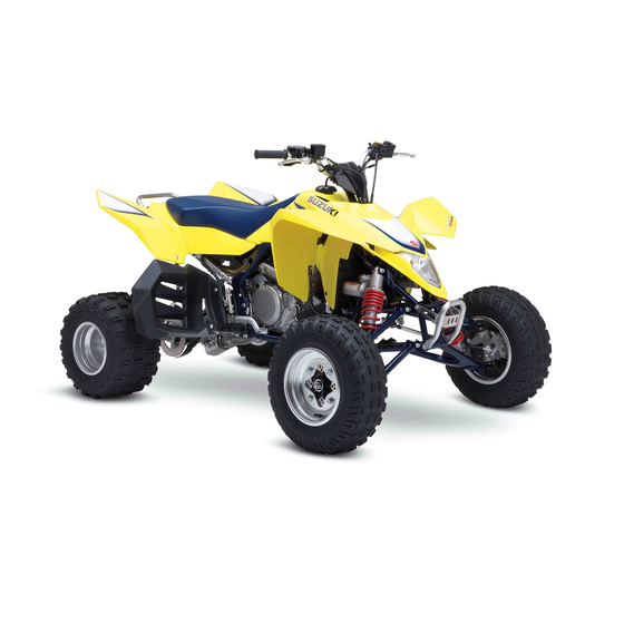
GENERAL INFORMATION SUZUKI LT-R450K6 (’06-MODEL) RIGHT SIDE LEFT SIDE • Difference between photograph and actual vehicle may exist depending on the markets. SERIAL NUMBER LOCATION The frame serial number or V.I.N. (Vehicle Identification Number) 1 is stamped on the right side of the steering head pipe. -
Page 13: Fuel, Oil And Engine Coolant Recommendation
Suzuki recommends the use of SUZUKI PERFORMANCE 4 MOTOR OIL or equivalent engine oil. Use of SF/SG or SH/SJ in API with MA in JASO. Suzuki recommends the use of SAE 10W-40 engine oil. If SAE 10W-40 engine oil is not available, select an alternative according to the following chart. -
Page 14: Engine Coolant
Suzuki recommends the use of SUZUKI COOLANT anti-freeze/engine coolant. If this is not available, use an equivalent which is compatible with an aluminum radiator. -
Page 15: Information Labels
GENERAL INFORMATION INFORMATION LABELS Upper surface of seat Right side of frame Front Left side of frame Swingarm Upper surface of fuel tank cover... -
Page 16: Specifications
GENERAL INFORMATION SPECIFICATIONS DIMENSIONS AND DRY MASS Overall length............1 845 mm (72.6 in) Overall width ............1 245 mm (49.0 in) Overall height............1 085 mm (42.7 in) Wheelbase ............1 285 mm (50.6 in) Front track............1 045 mm (41.1 in) Rear track ............ -
Page 17: Chassis
GENERAL INFORMATION CHASSIS Front suspension..........Independent, double wishbone, coil spring, oil damped Rear suspension ..........Swingarm type, coil spring, oil damped Front wheel travel..........254 mm (10.0 in) Rear wheel travel ..........277 mm (10.9 in) Caster..............8.0° Trail ..............30 mm (1.18 in) Toe-in .............. - Page 18 PERIODIC MAINTENANCE PERIODIC MAINTENANCE CONTENTS PERIODIC MAINTENANCE SCHEDULE ........... 2- 2 PERIODIC MAINTENANCE CHART .......... 2- 2 MAINTENANCE AND TUNE-UP PROCEDURES ......2- 3 AIR CLEANER ................2- 3 EXHAUST PIPE NUTS AND MUFFLER BOLTS ....... 2- 4 VALVE CLEARANCE ..............2- 5 SPARK PLUG ................
-
Page 19: Periodic Maintenance Schedule
PERIODIC MAINTENANCE PERIODIC MAINTENANCE SCHEDULE The chart below lists the recommended intervals for all the required periodic service work necessary to keep the vehicle operating at peak performance and economy. Maintenance intervals are expressed in terms of months. NOTE: More frequent servicing may be performed on vehicles that are use under severe conditions. PERIODIC MAINTENANCE CHART Interval Initial... -
Page 20: Maintenance And Tune-Up Procedures
PERIODIC MAINTENANCE MAINTENANCE AND TUNE-UP PROCEDURES This section describes the servicing procedures for each item mentioned in the Periodic Maintenance chart. AIR CLEANER Clean every 3 months. If the air cleaner is clogged with dust, intake resistance will be increased, with a resultant decrease in power output and an increase in fuel consumption. -
Page 21: Exhaust Pipe Nuts And Muffler Bolts
PERIODIC MAINTENANCE * Inspect the air cleaner element for tears. A torn ele- ment must be replaced. * If driving under dusty conditions, clean the air cleaner element more frequently. The surest way to accelerate engine wear is to operate the engine with- out the element or with torn element. -
Page 22: Valve Clearance
PERIODIC MAINTENANCE VALVE CLEARANCE Inspect initially at 1 month and every 6 months there- after. Excessive valve clearance results in valve noise and insufficient valve clearance results in valve damage and reduced power. Check the intake and exhaust valve clearances at the distances indicated above and adjust the valve clearances to specification, if necessary. - Page 23 PERIODIC MAINTENANCE • Rotate the crankshaft with a box wrench to set the piston at TDC on the compression stroke. (Rotate the crankshaft until the “T” line on the generator rotor is aligned with the triangle mark on the generator cover.) •...
- Page 24 After rotating the crankshaft, check the valve clearance again to make sure that it is within specification. • When installing the cylinder head cover, apply SUZUKI BOND “1216B” to the cam end caps of the cylinder head cover gas- ket.
- Page 25 PERIODIC MAINTENANCE INTAKE SIDE...
- Page 26 PERIODIC MAINTENANCE EXHAUST SIDE...
-
Page 27: Spark Plug
2-10 PERIODIC MAINTENANCE SPARK PLUG Inspect every 6 months. Replace every 18 months. • Remove the fuel tank and fuel tank lower cover. (%5-4) • Disconnect the spark plug cap 1 and remove the spark plug. Hot type Standard Cold type CR7EB CR8EB CR9EB... -
Page 28: Fuel Line
PERIODIC MAINTENANCE 2-11 FUEL LINE Inspect every 3 months. Replace every 4 years. Inspect the fuel hose for damage and fuel leakage. If any defects are found, replace the fuel hoses with new ones. FUEL FILTER Replace every 4 years. Inspect the fuel filter for damage and rust. -
Page 29: Engine Idle Speed
2-12 PERIODIC MAINTENANCE ENGINE IDLE SPEED Inspect initially at 1 month and every 3 months there- after. NOTE: Make this adjustment when the engine is hot. • Connect the tachometer to the high-tension cord. • Start the engine and set the engine idle speed between 1 700 and 1 900 r/min by turning the idle air screw 1. - Page 30 PERIODIC MAINTENANCE 2-13 ENGINE OIL REPLACEMENT Crankcase side • Remove the engine protector cover 1. • Place an oil pan below the drain plug 2 and 3 on the crank- case and drain plug 4 on the oil tank. Then drain out the engine oil by removing the engine oil drain plug 2, 3, 4 and engine oil filler cap 5, 6.
-
Page 31: Engine Oil Hose
2-14 PERIODIC MAINTENANCE • Install the new O-ring 3. • Install the spring 4 and new O-ring 5. Apply engine oil to the O-rings. • Replace the oil filter cap and tighten the bolts securely. NOTE: Face the triangle mark A on the cap rearward. •... -
Page 32: Engine Coolant
PERIODIC MAINTENANCE 2-15 ENGINE COOLANT Replace the engine coolant every 2 years. ENGINE COOLANT LEVEL CHECK • Check the engine coolant level by observing the upper A and lower B lines on the engine coolant reservoir. • If the level is below the lower line, remove the front fender (%7-6), add engine coolant until the level reaches the upper line. -
Page 33: Radiator
2-16 PERIODIC MAINTENANCE • Install the radiator cap securely. • After warming up and cooling down the engine, add engine coolant until the level is between the upper and lower lines on the engine coolant reservoir. Repeat the above procedure several times and make sure the radiator is filled with engine coolant to the upper line of the engine coolant reservoir. -
Page 34: Spark Arrester
PERIODIC MAINTENANCE 2-17 SPARK ARRESTER Clean every 6 months. • Disconnect the brake light/taillight coupler. • Remove the brake light/taillight cover 1 and rear brake light • Remove the spark arrester cover 3. • Remove the spark arrester pipe 4. •... -
Page 35: Clutch Cable Play
2-18 PERIODIC MAINTENANCE CLUTCH CABLE PLAY Inspect initially at 1 month and every 3 months there- after. Adjust the clutch cable play as follows: MAJOR ADJUSTMENT • Loosen the lock-nut 1. • Turn adjuster 2 so the clutch lever has 10 – 15 mm (0.4 – 0.6 in) play at the clutch lever end before pressure is felt. - Page 36 PERIODIC MAINTENANCE 2-19 FRONT BRAKE LEVER ADJUSTMENT Adjust the brake lever position as follows: • Loosen the lock-nut 1. • Turn in or out adjuster 2 to obtain the proper brake lever position. • The standard adjuster length A is 11 – 15 mm (0.4 – 0.6 in). •...
- Page 37 2-20 PERIODIC MAINTENANCE • Loosen the parking brake cable adjuster lock-nut 3. • Turn the cable adjuster 4 so that the cable length A is 49 – 53 mm (1.9 – 2.1 in). • Tighten the adjuster lock-nut 3. • Turn the parking brake adjuster 2 clockwise until it stops. •...
-
Page 38: Brake Fluid
PERIODIC MAINTENANCE 2-21 BRAKE FLUID Inspect every 3 months. Replace every 2 years. BRAKE FLUID LEVEL • Place the handlebar straight. • Check the brake fluid level by observing the lower limit lines on the front and rear brake fluid reservoirs. •... - Page 39 2-22 PERIODIC MAINTENANCE • Fill the front or rear brake reservoir with the specified brake fluid to the top of the inspection window or upper limit line. Replace the reservoir cap to prevent dirt from entering. • Attach a hose to the air bleeder valve, and insert the free end of the hose into a receptacle.
-
Page 40: Brake Hose
PERIODIC MAINTENANCE 2-23 BRAKE HOSE Inspect every 6 months. Replace every 4 years. Inspect the brake hoses for leakage, cracks, wear and damage. If any defects are found, replace the brake hoses with new ones. TIRES Inspect every 3 months. 4.0 mm TIRE TREAD CONDITION Operating the vehicle with excessively worn tires will decrease... -
Page 41: Steering
2-24 PERIODIC MAINTENANCE TIRE PRESSURE If the tire pressure is too high or too low, steering will be adversely affected and tire wear will increase. Therefore, main- tain the correct tire pressure for good roadability and a longer tire life. Cold inflation tire pressure is as follows. ' Cold inflation tire pressure Front: 45 kPa (0.45 kgf/cm , 6.5 psi) -
Page 42: Drive Chain
PERIODIC MAINTENANCE 2-25 • Place the vehicle on level ground. • Make sure the tire pressure for right and left tires is the same and set to the proper specification. • Set the front wheels in the straight position. • Place a load of 75 kg (165 lbs) on the seat. •... - Page 43 2-26 PERIODIC MAINTENANCE • Insert a tool into the rear sprocket hole and adjuster hole. • Tense the drive chain fully by turning rear axle holder 1. • Count out 21 pins (20 pitches) on the chain and measure the distance between the two points.
- Page 44 * Do not use any oil sold commercially as “drive chain oil”. Such oil can damage the O-rings. * The standard drive chain is a RK 520SMOZ10S. Suzuki recommends to use this standard drive chain as a replacement. DRIVE CHAIN BUFFER Inspect each time the vehicle is ridden.
-
Page 45: Suspensions
2-28 PERIODIC MAINTENANCE SUSPENSIONS Inspect every 6 months. • Support the vehicle with a jack or wooden blocks. • Remove the front and rear wheels. (%7-10) • Inspect the suspension arm and bearing for scratches, wear, or damage. If any defects are found, replace the suspension arm or bearing with a new one. -
Page 46: Rear Axle Nut And Lock-Nut
PERIODIC MAINTENANCE 2-29 REAR AXLE NUT AND LOCK-NUT Tighten initially at 1 month and every 3 months there- after. • Loosen the axle lock-nut 1 and axle nut 2 with the special tools. & 09940-92460: Rear axle nut wrench set •... -
Page 47: Chassis Bolts And Nuts
2-30 PERIODIC MAINTENANCE CHASSIS BOLTS AND NUTS Tighten initially at 1 month and every 3 months there- after. Check that all chassis nuts and bolts are tightened to their specified torque. (Refer to page 2-31, -32 for the locations of the following nuts and bolts on the vehicle.) Item N·m kgf-m... - Page 48 PERIODIC MAINTENANCE 2-31...
- Page 49 2-32 PERIODIC MAINTENANCE...
-
Page 50: General Lubrication
PERIODIC MAINTENANCE 2-33 GENERAL LUBRICATION Lubricate initially at 1 month and every 3 months thereafter. Proper lubrication is important for smooth operation and long life of each working part of the vehicle. Major lubrication points are indicated below. 1Brake lever holder 4Brake pedal and rod link Grease 2Throttle lever... -
Page 51: Compression Pressure Check
2-34 PERIODIC MAINTENANCE COMPRESSION PRESSURE CHECK The compression pressure reading of a cylinder is a good indicator of its internal condition. The decision to overhaul the cylinder is often based on the results of a compression test. Periodic mainte- nance records kept at your dealership should include compression readings for each maintenance service. ' Compression pressure: Standard: 800 kPa (8.0 kgf/cm², 114 psi) (Automatic decompression actuated) -
Page 52: Oil Pressure Check
PERIODIC MAINTENANCE 2-35 OIL PRESSURE CHECK Check the engine oil pressure periodically. This will give a good indication of the condition of the moving parts. ' Oil pressure: 10 kPa (0.1 kgf/cm², 1.4 psi) at 3 000 r/min, Oil temp. at 60 °C (140 °F) If the oil pressure is lower or higher than the specification, the following causes may be considered. -
Page 53: Sds Check
2-36 PERIODIC MAINTENANCE SDS CHECK Using SDS, take the sample of data from the new vehicle and at the time of periodic maintenance at your dealership. Save the data in the computer or by printing and filing the hard copies. The saved or filed data are useful for troubleshooting as they can be compared periodically with changes over time or failure conditions of the vehicle. - Page 54 PERIODIC MAINTENANCE 2-37 Data at 3 000 r/min under no load 3 000 r/min Check the manifold absolute pressure. XXX kPa (XXX mmHg) Data at the time of racing Throttle: Slowly open Throttle: Quick wide open...
- Page 55 2-38 PERIODIC MAINTENANCE Data of intake negative pressure during idling (100 °C) Check the manifold absolute pressure. Approx. XXX kPa (XXX mmHg)
- Page 56 ENGINE ENGINE CONTENTS ENGINE COMPONENTS REMOVABLE WITH ENGINE IN PLACE .................... 3- 2 ENGINE LEFT SIDE ..............3- 2 ENGINE RIGHT SIDE ..............3- 2 ENGINE CENTER ............... 3- 2 ENGINE REMOVAL AND REMOUNTING .......... 3- 3 ENGINE REMOVAL ..............3- 3 ENGINE INSTALLATION ............
-
Page 57: Engine Components Removable With Engine In Place
ENGINE ENGINE COMPONENTS REMOVABLE WITH ENGINE IN PLACE The parts listed below can be removed and installed without removing the engine from the frame. Refer to the page listed in each section for removal and installation instructions. ENGINE LEFT SIDE PARTS REMOVAL INSTALLATION... -
Page 58: Engine Removal And Remounting
ENGINE ENGINE REMOVAL AND REMOUNTING ENGINE REMOVAL Before taking the engine out of the frame, wash the engine using a steam cleaner. Engine removal is sequentially explained in the following steps. • Drain engine coolant. (%2-15) • Drain engine oil. (%2-13) •... - Page 59 ENGINE • Disconnect the ECT sensor coupler • Loosen the muffler clamp bolt. • Remove the exhaust pipe 7. • Remove the gasket 8. • Remove the muffler 9. • Disconnect the motor lead wire.
- Page 60 ENGINE • Remove the starter motor lead wire 0 and wiring harness A from the clamp. • Disconnect the ground lead wire coupler B. • Remove the parking brake cable C from the bracket. • Disconnect the generator startor coupler D, CKP sensor E and gear position switch coupler F.
- Page 61 ENGINE • Remove the engine sproket cover J. • Remove the gearshift lever K. • Remove the clutch cable bracket L. • Remove the clutch release arm M along with the clutch cable. • Remove the engine sprocket N with drive chain. •...
- Page 62 ENGINE • Remove the swingarm pivot shaft nut and washer. • Extract three quarters of the swingarm pivot shaft so as to keep the swingarm is position. NOTE: The swingarm will come off when the swingarm pivot shaft is completely removed. •...
-
Page 63: Engine Installation
ENGINE ENGINE INSTALLATION Install the engine in the reverse order of engine removal. Pay attention to the following points: • Tighten the swingarm pivot shaft nut to the specified torque. NOTE: * The engine mounting nuts are self-locking. * Once the nut has been removed, it is no longer of any use. Be sure to use new nuts, and then tighten them to the specified torque. - Page 64 ENGINE • Install the engine sprocket with drive chain. NOTE: The letter F on the engine sprocket should face to the outside. • Apply THREAD LOCK SUPER “1303” to the sprocket bolts. + 99000-32030: THREAD LOCK SUPER “1303” • Tighten the engine sprocket bolts to the specified torque. "...
- Page 65 3-10 ENGINE • Install the muffler 3 and exhaust pipe 4. Use new gaskets to prevent exhaust gas leakage. " Muffler mounting bolt: 23 N·m (2.3 kgf-m, 16.5 lb-ft) Exhaust pipe bolt: 23 N·m (2.3 kgf-m, 16.5 lb-ft) Muffler connecting bolt: 23 N·m (2.3 kgf-m, 16.5 lb-ft) •...
-
Page 66: Engine Disassembly
ENGINE 3-11 ENGINE DISASSEMBLY STARTER MOTOR • Remove the starter motor 1. GEAR POSITION SWITCH • Remove the gear position switch 1. • Remove the O-ring 2, switch contacts 3 and springs 4. • Remove the spark plug. & 09930-10121: Spark plug wrench set CYLINDER HEAD COVER •... - Page 67 3-12 ENGINE CAMSHAFT • Remove the valve timing inspection plug 1 and generator cover cap 2. • Turn the generator rotor until the “T” line on the generator rotor is aligned with the center of the hole in the generator cover.
- Page 68 ENGINE 3-13 • Remove the dowel pins, intake camshaft 8, exhaust cam- shaft 9 and C-rings 0. Do not drop the dowel pins, cam chain and C-rings into the crankcase. CYLINDER HEAD • Remove the cylinder head bolts 1. • Loosen the cylinder hase bolt 2. •...
- Page 69 3-14 ENGINE • Remove the cylinder gasket 3 and dowel pins. PISTON • Place a clean rag over the cylinder base to prevent the piston pin circlip from dropping into the crankcase. • Remove the piston pin circlip. • Draw out the piston pin 1 and remove the piston 2. GENERATOR ROTOR COVER •...
- Page 70 ENGINE 3-15 • Remove the generator rotor cover. • Remove the shaft 4, starter idle gear 5, gasket 6 and dowel pins. OIL FILTER • Remove the oil filter cap 1. • Remove the oil filter 2 and O-ring 3. CLUTCH COVER •...
- Page 71 3-16 ENGINE • Remove the gasket 2. RIGHT CRANKCASE COVER • Remove the right crankcase cover 1. • Remove the gasket 2, dowel pins and oil seal 3. NOTE: If there is no wear or damage at oil seal lip, the oil seal 3 removal is not necessary.
- Page 72 ENGINE 3-17 • Remove the drive plates 2 and driven plates 3. • Remove the spring washer and spring washer seat. • Remove the push piece 4 and push rod 5. • Flatten the lock washer 6. • Hold the clutch sleeve hub using the special tool, and then remove the clutch sleeve hub nut.
- Page 73 3-18 ENGINE • Remove the spacer 0. OIL PUMP (No.1) • Remove the oil pump idle gear 1 and oil pump driven gear & 09900-06107: Snap ring pliers • Remove the pin 3, washer 4 and oil pump assembly 5. •...
- Page 74 ENGINE 3-19 • Remove the gearshift pawl lifter 3 and gearshift cam driven gear 4. NOTE: Be careful not to drop the pins and springs when removing the gearshift cam driven gear. • Remove the gearshift pawls 5, pins 6 and springs 7. •...
- Page 75 3-20 ENGINE • Remove the washer 1, balancer driven gear 2. • Remove the pin 3. • Hold the generator rotor using the special tool, and then remove the primary drive gear nut. The primary drive gear nut has left-hand threads. &...
- Page 76 ENGINE 3-21 • Remove the generator rotor using the special tool. & 09930-31921: Rotor remover NOTE: Temporarily install the generator rotor nut to the crankshaft, and then remove the generator rotor using the special tool. Do not hit the generator rotor with a hammer, otherwise the rotor may be damaged.
- Page 77 3-22 ENGINE BALANCER CRANK • Remove the balancer crank 1. CRANKCASE • Remove the retainer 1. • Remove the spacer 2. • Remove the gearshift fork shaft retainer 3. Do not pull out the gearshift fork shaft 4 at this point because the gearshift fork comes off in the crankcase.
- Page 78 ENGINE 3-23 • Remove the dowel pins. • Remove the oil strainers 4. • Remove the gearshift fork shafts 5, gearshift forks 6 and gearshift cam 7. • Remove the countershaft assembly 8 and driveshaft assem- bly 9. • Remove the crankshaft from the crankcase using the special tool.
-
Page 79: Engine Components Inspection And Service
3-24 ENGINE ENGINE COMPONENTS INSPECTION AND SERVICE CYLINDER HEAD DISASSEMBLY Identify the position of each removed part. Organize the parts in their respective groups (i.e., exhaust or intake) so that they can be installed in their original locations. • Remove the intake pipe 1. •... - Page 80 ENGINE 3-25 • Remove the tappets 4 and shims 5 by fingers or magnetic hand. Identify the position of each removed part. • Using the special tools, compress the valve spring and remove the two cotter halves 6 from the valve stem. &...
- Page 81 3-26 ENGINE • Remove the oil seal 0 and spring seat A. Do not reuse the removed oil seal. • Remove the other valves in the same manner as described previously. CYLINDER HEAD DISTORTION Decarbonize the combustion chambers. Check the gasket surface of the cylinder head for distortion with a straightedge and thickness gauge, taking a clearance reading at several places indicated.
- Page 82 ENGINE 3-27 VALVE STEM AND VALVE FACE WEAR CONDITION Visually inspect each valve stem and valve face for wear and pit- ting. If it is worn or damaged, replace the valve with a new one. VALVE STEM DEFLECTION Lift the valve about 10 mm (0.39 in) from the valve seat. Measure the valve stem deflection in two directions, perpendicu- lar to each other, by positioning the dial gauge as shown.
- Page 83 3-28 ENGINE VALVE GUIDE SERVICING • Using the valve guide remover, drive the valve guide out toward the intake or exhaust camshaft side. & 09916-44910: Valve guide remover/installer NOTE: * Discard the removed valve guide subassemblies. * Only oversized valve guides are available as replacement parts.
- Page 84 ENGINE 3-29 • After installing the valve guides, re-finish their guiding bores using the reamer. • Clean and engine oil the guides after reaming. & 09916-34550: Valve guide reamer (5.5 mm) 09916-34542: Reamer handle NOTE: * Be sure to cool down the cylinder head to ambient air temper- ature.
- Page 85 3-30 ENGINE VALVE SEAT SERVICING • The valve seats 1 for both the intake valve 2 and exhaust valve 3 are machined to three different angles. The seat con- tact surface is cut at 45°. ˚ ˚ ˚ ˚ ˚ INTAKE EXHAUST ˚...
- Page 86 ENGINE 3-31 VALVE SPRING The force of the coil spring keeps the valve seat tight. Weak- ened spring results in reduced engine power output, and often accounts for the chattering noise coming from the valve mecha- nism. Check the valve spring for proper strength by measuring its free length and also by the force required to compress it.
- Page 87 3-32 ENGINE • Install the valve spring with the small-pitch portion A facing cylinder head. B Large-pitch portion C UPWARD D Paint • Put on the valve spring retainer 2, and using the valve lifter, press down the spring, fit the valve cotter halves to the stem end, and release the lifter to allow the valve cotter 3 to wedge in between retainer and stem.
-
Page 88: Automatic Decomp
ENGINE 3-33 • Install the ETC sensor. (%6-11) • Apply SUZUKI SUPER GREASE to the O-ring. - 99000-25010: SUZUKI SUPER GREASE “A” (or equivalent grease) The removed O-ring must be replaced with a new one. • Apply THREAD LOCK SUPER “1303” to the intake pipe bolts. - Page 89 3-34 ENGINE CAMSHAFT BEARING Inspect the bearings for play, discoloration, wear and seizure. Move the outer race by finger and inspect for smooth move- ment. If there is anything unusual, replace the camshaft assem- bly. CAM WEAR • Check the camshaft for wear or damage. •...
- Page 90 ENGINE 3-35 • If the camshaft journal oil clearance measured exceeds the limit, measure the inside diameter of the camshaft journal holder and outside diameter of the camshaft journal. • Replace the camshaft or the cylinder head depending upon which one exceeds the specification. ' Camshaft journal holder I.D.: Standard: (IN &...
-
Page 91: Cam Chain Tension Adjuster And Tensioner
3-36 ENGINE CAM CHAIN TENSION ADJUSTER AND TENSIONER Check that the push rod slides smoothly when unlocking the ratchet mechanism 1. If push rod does not slide smoothly, replace the cam chain ten- sion adjuster with a new one. • Remove the cam chain guide 2 from cylinder head cover. Check the contacting surface of the cam chain tensioner and cam chain guides. -
Page 92: Piston And Piston Ring
ENGINE 3-37 CYLINDER BORE Inspect the cylinder wall for any scratches, nicks or other dam- age. Measure the cylinder bore diameter at six places. If any one of the measurements exceed the limit, replace the cyl- inder. ! Cylinder bore Standard: 95.500 –... - Page 93 3-38 ENGINE PISTON PIN AND PIN BORE Measure the piston pin bore diameter using the small bore gauge. If the measurement is out of specifications replace the piston. Piston pin bore I.D.: Service Limit: 19.030 mm (0.7492 in) 09900-20602: Dial gauge (1/1 000 mm) 09900-22403: Small bore gauge (18 –...
-
Page 94: Conrod
ENGINE 3-39 ' Piston ring thickness Standard: 1st: 0.71 – 0.76 mm (0.0280 – 0.0299 in) 1.08 – 1.10 mm (0.0425 – 0.0433 in) 2nd: 0.77 – 0.79 mm (0.0303 – 0.0311 in) PISTON RING END GAP Fit the piston ring squarely into the cylinder and measure the piston ring end gap using the thickness gauge. -
Page 95: Crankshaft
3-40 ENGINE CONROD DEFLECTION AND BIG END SIDE CLEARANCE Wear on the big end of the conrod can be estimated by checking the movement of the small end of the rod. This method can also be used to check the extent of wear on the parts of the conrod big end. -
Page 96: Balancer Shaft And Balancer Driven And Drive Gear
ENGINE 3-41 BALANCER SHAFT AND BALANCER DRIVEN AND DRIVE GEAR INSPECTION Inspect the balancer shaft and balancer driven and drive gear for wear or damage. If any defects are found, replace the defec- tive part. STARTER CLUTCH INSPECTION Install the starter driven gear onto the starter clutch and turn the starter driven gear by hand to inspect the starter clutch for a smooth movement. - Page 97 3-42 ENGINE • Tighten the bolts while holding the rotor using the special tool. " Starter clutch bolt: 10 N·m (1.0 kgf-m, 7.0 lb-ft) & 09930-44520: Rotor holder STARTER DRIVEN GEAR BEARING INSPECTION Inspect the starter driven gear bearing for any damages. STARTER DRIVEN GEAR BEARING REPLACEMENT •...
-
Page 98: Generator
ENGINE 3-43 GENERATOR INSPECTION (%8-9, -21) • Remove the generator stator 1, CKP sensor 2, bracket 3 and grommet 4. • When replacing the generator stator or CKP sensor, route the wire properly. • Apply a small quantity of THREAD LOCK SUPER “1303” to the generator stator mounting bolts, and tighten them securely. -
Page 99: Oil Pump
3-44 ENGINE OIL PUMP INSPECTION Inspect the outer rotor 1 and inner rotor 2 for any scratches or other damage. If any damages are found, replace them with new ones. Rotate the oil pump by hand and check that it moves smoothly. If it does not move smoothly, replace the oil pump assembly. -
Page 100: Clutch
ENGINE 3-45 CLUTCH CLUTCH DRIVE PLATE NOTE: Wipe off engine oil from the clutch drive plates with a clean rag. Measure the thickness of drive plates using the vernier calipers. If the drive plate thickness is found to have reached the limit, replace it with a new one. - Page 101 3-46 ENGINE PUSH ROD Inspect the push rod for wear and damage. If any defects are found, replace the push rod with a new one. RELEASE BEARING Inspect the release bearing for play, wear and damage. Move the inner race by finger and inspect for smooth movement. If any defects are found, replace the release bearing with a new one.
-
Page 102: Gearshift Fork And Gear
ENGINE 3-47 GEARSHIFT FORK AND GEAR GEARSHIFT FORK-TO-GROOVE CLEARANCE Using a thickness gauge, check the gearshift fork clearance in the groove of its gear. The clearance for each gearshift fork plays an important role in the smoothness and positiveness of the shifting action. ' Shift fork-to-groove clearance: Service Limit: 0.5 mm (0.020 in) &... -
Page 103: Transmission
3-48 ENGINE TRANSMISSION DISASSEMBLY Disassemble the transmission gears as shown in the illustration. 1 Countershaft 5 2nd drive gear 9 3rd driven gear 2 5th drive gear 6 Driveshaft 0 5th driven gear 3 3rd drive gear 7 2nd driven gear A 1st driven gear 4 4th drive gear 8 4th driven gear... - Page 104 ENGINE 3-49 REASSEMBLY Reassemble the countershaft and driveshaft in the reverse order of disassembly. Pay attention to the following points: NOTE: * Before installing the gears, apply engine oil to the inner surface of each gear and bushing. * Apply molybdenum oil solution to the surface of countershaft and inner surface of 5th drive gear 1.
- Page 105 3-50 ENGINE 1 Countershaft 2 Driveshaft...
-
Page 106: Oil Strainer
ENGINE 3-51 OIL STRAINER • Clean the oil strainers using the compressed air. CRANKCASE GEARSHIFT ARM STOPPER • Remove the gearshift arm stopper 1 and washer 2. • Apply a small quantity of THREAD LOCK SUPER “1303” to the gearshift arm stopper. •... - Page 107 The removed oil seals must be replaced with new ones. & 09913-70210: Bearing installer set • Apply SUZUKI SUPER GREASE “A” to the lip of the oil seals. - 99000-25010: SUZUKI SUPER GREASE “A” (or equivalent grease) • Install the crankcase plate.
- Page 108 ENGINE 3-53 Remove the bearings using the special tool. & 09913-70210: Bearing installer set Bearing 4: . 22 Attachment Bearing 3: . 25 Attachment Bearing 6, 8: . 30 Attachment Bearing 1, 5, 7: . 35 Attachment Bearing 2: . 42 Attachment •...
- Page 109 3-54 ENGINE INSTALLATION • Press the bearings using the special tool. Bearing A: . 20 Attachment Bearing 3, 0: . 32 Attachment Bearing 9: . 40 Attachment Bearing 6, 8: . 42 Attachment Bearing 7: . 52 Attachment Bearing 1: . 62 Attachment Bearing 2, 5: .
- Page 110 ENGINE 3-55 CLUTCH RELEASE CAMSHAFT INSPECTION Rotate the clutch release camshaft by finger to inspect for abnormal noise or smooth movement. If any defects are found, replace the clutch release camshaft or bearings with new ones. CLUTCH RELEASE CAMSHAFT AND BEARING REPLACEMENT •...
-
Page 111: Right Crankcase Cover
ENGINE • Apply engine oil to the bearings. • Apply grease to the oil seal lip. - 99000-25010: SUZUKI SUPER GREASE “A” (or equivalent grease) • Install the clutch release camshaft correctly. The removed bearings and oil seal must be replaced with new ones. -
Page 112: Gearshift Shaft
ENGINE 3-57 GEARSHIFT SHAFT DISASSEMBLY • Remove the following parts from the gearshift shaft 1. 2 Shim 3 Snap ring 4 Return spring & 09900-06107: Snap ring pliers INSPECTION Inspect the gearshift shaft for bend or damage. Inspect the return spring for damage or fatigue. Replace the defective parts with a new one if necessary. -
Page 113: Engine Reassembly
3-58 ENGINE ENGINE REASSEMBLY Reassemble the engine in the reverse order of disassembly. The following steps require special attention or precautionary measures should be taken. NOTE: Apply engine oil to each running and sliding part before reassembling. CRANKSHAFT 1 Bearing 4 Bearing 7 Bearing 2 Crankshaft (R) - Page 114 ENGINE 3-59 Never fit the crankshaft into the crankcase by striking it with a plastic hammer. Always use the special tool, otherwise the accuracy of the crankshaft alignment will be affected. COUNTERSHAFT/DRIVESHAFT • Install the countershaft assembly and driveshaft assembly. GEARSHIFT CAM, FORK AND SHAFT •...
- Page 115 3-60 ENGINE • Apply SUZUKI BOND “1215” to the mating surface of the right crankcase as shown. / 99000-31110: SUZUKI BOND “1215” (or equivalent bond) NOTE: Use of SUZUKI BOND “1215” is as follows: * Make surfaces free from moisture, oil, dust and other foreign materials.
- Page 116 ENGINE 3-61 • Tighten the crankcase bolts and engine oil drain plug 2 to the specified torque. " Crankcase bolt: 11 N·m (1.1 kgf-m, 8.0 lb-ft) Engine oil drain plug: 18 N·m (1.8 kgf-m, 13.0 lb-ft) • After the crankcase bolts have been tightened, check if the crankshaft, countershaft, and driveshaft rotate smoothly.
- Page 117 3-62 ENGINE • Apply engine oil to the outer rotor. • Install the outer rotor 4 to the left crankcase. • Apply engine oil to the oil pump shaft and inner rotor. The punch mark B on the outer rotor must face to the crankcase side.
- Page 118 ENGINE 3-63 • Install the generator rotor. • Tighten the generator rotor nut to the specified torque using the special tool. " Generator rotor nut: 120 N·m (12.0 kgf-m, 87.0 lb-ft) & 09930-44520: Rotor holder PRIMARY DRIVE GEAR AND BALANCER GEAR •...
- Page 119 3-64 ENGINE • Hold the generator rotor using the special tool, and then tighten the primary drive gear nut to the specified torque. Primary drive gear nut: 155 N·m (15.5 kgf-m, 112.0 lb-ft) NOTE: This nut has left-hand thread. ...
- Page 120 ENGINE 3-65 • Apply a small quantity of THREAD LOCK SUPER “1303” to the gearshift cam driven gear bolt. • Tighten the gearshift cam driven gear bolt to the specified torque. " Gearshift cam driven gear bolt: 31 N·m (3.1 kgf-m, 22.5 lb-ft) + 99000-32030: THREAD LOCK SUPER “1303”...
- Page 121 3-66 ENGINE • Install the washer 7 and new snap ring 8. & 09900-06107: Snap ring pliers OIL PUMP No.1 • Install the oil pump body 2, inner rotor 3 and pin 4 to oil pump shaft 1. NOTE: Fit the slot A of the inner rotor on the pin 4 . The slit must face to the crankcase side.
- Page 122 ENGINE 3-67 • Install the oil pump idle gear A. & 09900-06107: Snap ring pliers CLUTCH • Apply engine oil to the spacer. • Install the spacer 1. • Install the primary driven gear assembly 2. • Install the washer 3. •...
- Page 123 3-68 ENGINE • Bend the tongue of the washer securely. • Install the push rod 7 and push piece 8. • Install the spring washer seat 9 and spring washer 0 onto the clutch sleeve hub correctly. • Apply engine oil to the drive plates A and driven plates B. •...
- Page 124 ENGINE 3-69 Direction of outside Paint Driven No.1 plate Black Driven No.2 plate Blue Paint Paint • Apply engine oil to the release bearing C. • Install the clutch pressure plate D. • Hold the generator rotor using the special tool. •...
- Page 125 3-70 ENGINE • Tighten the right crankcase cover bolts securely. • Install the gasket G. Use a new gasket to prevent oil leakage. • Tight the clutch cover bolts securely. C: Bolt with clamp OIL FILTER • Apply engine oil to the O-ring. •...
- Page 126 ENGINE 3-71 • Replace the oil filter cap and tighten the bolts securely. NOTE: Face the triangle mark A on the cap rearward. GENERATOR ROTOR COVER • Before installing the starter idle gear, apply molybdenum oil solution to the hole of starter idle gear shaft. , MOLYBDENUM OIL SOLUTION •...
- Page 127 3-72 ENGINE • Apply engine oil to the O-ring 7. • Install the starter torque limiter assembly cover 8. PISTON RING • Install the piston rings in the order of oil ring, 2nd ring and 1st ring. • The first member to go into the oil ring groove is a spacer 1. After placing the spacer, fit the two side rails 2.
- Page 128 End gap of the circlip should not be aligned with the cutaway in the piston pin bore. • Thoroughly wipe off oil from the fitting surface of the crank- case. • Apply SUZUKI BOND “1215” to the crankcase B as shown. / 99000-31110: SUZUKI BOND “1215” (or equivalent bond)
- Page 129 3-74 ENGINE • Apply molybdenum oil solution to the sliding surface of the piston and piston rings. • Install the dowel pins and gasket 1 onto the crankcase. Use a new gasket to prevent oil leakage. , MOLYBDENUM OIL SOLUTION •...
- Page 130 ENGINE 3-75 CYLINDER HEAD • With the head snugly seated on the cylinder, secure it by tightening the bolts in diagonal stages. Tighten the cylinder head bolts diagonally to the specified torque. " Cylinder head bolt Initial: 25 N·m (2.5 kgf-m, 18.0 lb-ft) Final: 47 N·m (4.7 kgf-m, 34.0 lb-ft) NOTE: * Apply engine oil to the threaded parts of the cylinder head...
- Page 131 3-76 ENGINE • Just before installing the camshaft into the cylinder head, apply engine oil to the camshaft journals, cam faces, cam- shaft journal holders and camshaft bearings. • With the “T” line aligned with the center of the hole, hold the camshaft steady and lightly pull up the cam chain to remove any slack between the cam chain drive sprocket and exhaust camshaft sprocket.
- Page 132 ENGINE 3-77 • Install the dowel pins and C-ring 1. • Place each camshaft journal holders into the correct position. NOTE: Camshaft journal holders marked “EX” are for the exhaust side and those marked “IN” are for the intake side. •...
- Page 133 CYLINDER HEAD COVER • Thoroughly wipe off oil from the fitting surfaces of the cylinder head and cover. • Apply SUZUKI BOND “1216B” to the end caps of the cylinder head cover gasket as shown. ( 99000-31230: SUZUKI BOND “1216B”...
- Page 134 • Install the O-ring 1, springs 2 and contacts 3. Use a new O-ring to prevent oil leakage. - 99000-25010: SUZUKI SUPER GREASE “A” (or equivalent grease) • Install the gear position switch 4 and tighten the bolts to the specified torque.
- Page 135 FI SYSTEM DIAGNOSIS FI SYSTEM DIAGNOSIS CONTENTS PRECAUTIONS IN SERVICING ..............4- 3 ELECTRICAL PARTS ................4- 3 FUSE...................... 4- 4 ECM/VARIOUS SENSORS ..............4- 4 ELECTRICAL CIRCUIT INSPECTION PROCEDURE......4- 6 USING THE MULTI-CIRCUIT TESTER..........4- 9 FI SYSTEM TECHNICAL FEATURES............4-10 INJECTION TIME (INJECTION VOLUME) ...........
- Page 136 FI SYSTEM DIAGNOSIS FI SYSTEM DIAGNOSIS CONTENTS SENSORS ....................4-60 CKP SENSOR INSPECTION ..............4-60 CKP SENSOR REMOVAL AND INSTALLATION ........ 4-60 IAP SENSOR INSPECTION ..............4-60 IAP SENSOR REMOVAL AND INSTALLATION........4-60 TP SENSOR INSPECTION ..............4-60 TP SENSOR REMOVAL AND INSTALLATION ........4-60 TPS ADJUSTMENT................
-
Page 137: Precautions In Servicing
FI SYSTEM DIAGNOSIS 4-3 PRECAUTIONS IN SERVICING When handling the component parts or servicing the FI system, observe the following points for the safety of the system. ELECTRICAL PARTS CONNECTOR/COUPLER • Faulty FI system is often related to poor electrical contact of connector/coupler. -
Page 138: Fuse
FI SYSTEM DIAGNOSIS • When connecting meter probe from the terminal side of the coupler (where connection from harness side not being possi- ble), use extra care not to force and cause the male terminal to bend or the female terminal to open. Connect the probe as shown to avoid opening of female ter- minal. - Page 139 FI SYSTEM DIAGNOSIS • When disconnecting and connecting the ECM, make sure to turn OFF the ignition switch 1, or electronic parts may get damaged. INCORRECT • Battery connection in reverse polarity is strictly prohibited. Such a wrong connection will damage the components of the FI system instantly when reverse power is applied.
-
Page 140: Electrical Circuit Inspection Procedure
FI SYSTEM DIAGNOSIS ELECTRICAL CIRCUIT INSPECTION PROCEDURE While there are various methods for electrical circuit inspection, described here is a general method to check for open and short circuit using an ohmmeter and a voltmeter. OPEN CIRCUIT CHECK Possible causes for the open circuits are as follows. As the cause can exist in the connector/coupler or terminal, they need to be checked carefully. - Page 141 FI SYSTEM DIAGNOSIS Continuity check • Measure resistance across coupler B (between A and C in the figure). If no continuity is indicated (infinity or over limit), the circuit is open between terminals A and C. 1 ECM • Disconnect the coupler B and measure resistance between couplers A and B.
- Page 142 FI SYSTEM DIAGNOSIS SHORT CIRCUIT CHECK (WIRE HARNESS TO GROUND) • Disconnect the negative cable from the battery. • Disconnect the connectors/couplers at both ends of the circuit to be checked. NOTE: If the circuit to be checked branches to other parts as shown, disconnect all connectors/couplers of those parts.
-
Page 143: Using The Multi-Circuit Tester
FI SYSTEM DIAGNOSIS USING THE MULTI-CIRCUIT TESTER • Use the Suzuki multi-circuit tester set (09900-25008). • Use well-charged batteries in the tester. • Be sure to set the tester to the correct testing range. USING THE TESTER • Incorrectly connecting the + and - probes may cause the inside of the tester to burnout. -
Page 144: Fi System Technical Features
4-10 FI SYSTEM DIAGNOSIS FI SYSTEM TECHNICAL FEATURES INJECTION TIME (INJECTION VOLUME) The factors to determine the injection time include the basic fuel injection time, which is calculated on the basis of intake air pressure, engine speed and throttle opening angle, and various compensations. These compensations are determined according to the signals from various sensors that detect the engine and driving conditions. -
Page 145: Compensation Of Injection Time (Volume)
FI SYSTEM DIAGNOSIS 4-11 COMPENSATION OF INJECTION TIME (VOLUME) The following different signals are output from the respective sensors for compensation of the fuel injection time (volume). SIGNAL DESCRIPTION ENGINE COOLANT TEMPERATURE SEN- When engine coolant temperature is low, injection time (vol- SOR SIGNAL ume) is increased. -
Page 146: Fi System Parts Location
4-12 FI SYSTEM DIAGNOSIS FI SYSTEM PARTS LOCATION A Intake air temperature sensor (IATS) B Ignition coil (IG COIL) C Engine coolant temperature sensor (ECTS) D Cooling fan relay E Cooling fan... - Page 147 FI SYSTEM DIAGNOSIS 4-13 F Fuel pump relay (FP RERAY) G Tip-over sensor (TOS) H Intake air pressure sensor (IAPS) I Fuel injector J Throttle position sensor (TPS) K Fuel pump (FP) L Crankshaft position sensor (CKPS) M Gear position switch...
-
Page 148: Fi System Wiring Diagram
4-14 FI SYSTEM DIAGNOSIS FI SYSTEM WIRING DIAGRAM... -
Page 149: Ecm Terminal
FI SYSTEM DIAGNOSIS 4-15 ECM TERMINAL TERMINAL TERMINAL CIRCUIT CIRCUIT Power source — TO sensor signal (TOS) Blank CKP sensor signal (CKP+) FI/ECT indicator GP switch signal (GP) ECT sensor signal (ECT) TP sensor signal (TP) Blank IAP sensor signal (IAP) Sensors ground (E2) Blank IAT sensor signal (IAT) -
Page 150: Self-Diagnosis Function
4-16 FI SYSTEM DIAGNOSIS SELF-DIAGNOSIS FUNCTION The self-diagnosis function is incorporated in the ECM. The function has two modes, “User mode” and “Dealer mode”. The user can only be notified by the FI light. To check the function of the individual FI system devices, the dealer mode is provided. -
Page 151: Dealer Mode
FI SYSTEM DIAGNOSIS 4-17 DEALER MODE The defective function is memorized in the computer. Use the special tool’s coupler to connect to the dealer mode coupler. The memorized malfunction code is displayed on FI light. Malfunction means that the ECM does not receive signal from the devices. -
Page 152: Diagnostic Trouble Code Table
4-18 FI SYSTEM DIAGNOSIS DIAGNOSTIC TROUBLE CODE TABLE EXAMPLE: When intake air pressure sensor and intake air tempreture sensor defective (Code No.13 and 21) FI light Code No.13 Code No.21 Code No.13 Code No.21 0.3 0.3 Time (sec.) FI LIGHT DTC NO. -
Page 153: Tps Adjustment
FI SYSTEM DIAGNOSIS 4-19 TPS ADJUSTMENT 1. Adjust the engine rpm to 1 800 r/min. (%2-12) 2. If the throttle position sensor adjustment is necessary, remove the fuel tank cover (%7-6), fuel pump (%5-6) and follow the procedure below. 3. Loosen the screw and turn the throttle position sensor 1 and connect the TP sensor coupler 2 to the test harness. -
Page 154: Fail-Safe Function
4-20 FI SYSTEM DIAGNOSIS FAIL-SAFE FUNCTION FI system is provided with fail-safe function to allow the engine to start and the vehicle to run in a minimum performance necessary even under malfunction condition. STARTING RUNNING ITEM FAIL-SAFE MODE ABILITY ABILITY IAP sensor Intake air pressure is fixed to 101 “YES”... -
Page 155: Fi System Troubleshooting
FI SYSTEM DIAGNOSIS 4-21 FI SYSTEM TROUBLESHOOTING CUSTOMER COMPLAINT ANALYSIS Record details of the problem (failure, complaint) and how it occurred as described by the customer. For this purpose, use of such an inspection form such as below will facilitate collecting information required for proper analysis and diagnosis. -
Page 156: Visual Inspection
4-22 FI SYSTEM DIAGNOSIS VEHICLE/ENVIRONMENTAL CONDITION WHEN PROBLEM OCCURS Environmental condition Weather Fair Cloudy Rain Snow Always Other Temperature Warm Cool Cold ( °C / °F ) Always Frequency Always Sometimes ( times/ day, month) Only once Under certain condition Road Urban Suburb... -
Page 157: Self-Diagnostic Procedures
FI SYSTEM DIAGNOSIS 4-23 SELF-DIAGNOSTIC PROCEDURES NOTE: * Do not disconnect couplers from the ECM, the battery cable from the battery, ECM ground wire harness from the engine or main fuse before confirming the malfunction code (self-diag- nostic trouble code) stored in memory. Such disconnection will erase the memorized information in ECM memory. -
Page 158: Use Of Sds Diagnostic Procedures
4-24 FI SYSTEM DIAGNOSIS USE OF SDS DIAGNOSTIC PROCEDURES * Do not disconnect couplers from ECM, the battery cable from the battery, ECM ground wire harness from the engine or main fuse before confirming the malfunction code (self-diagnostic trouble code) stored in memory. Such disconnection will erase the memorized information in ECM memory. -
Page 159: Use Of Sds Diagnosis Reset Procedure
FI SYSTEM DIAGNOSIS 4-25 USE OF SDS DIAGNOSIS RESET PROCEDURE • After repairing the trouble, turn OFF the ignition switch and turn ON again. • Click the DTC inspection button 1. • Check the DTC. • The previous malfunction history code (Past DTC) still remains stored in the ECM. -
Page 160: Show Data When Trouble (Displaing Data At The Time Of Dtc)
4-26 FI SYSTEM DIAGNOSIS SHOW DATA WHEN TROUBLE (DISPLAING DATA AT THE TIME OF DTC) ECM stores the engine and driving conditions (in the form of data as shown in the figure) at the moment of the detection of a malfunction in its memory. This data is called “Show data when trouble”. Therefore, it is possible to know engine and driving conditions (e.g., whether the engine was warm or not, where the vehicle was running or stopped) when a malfunction was detected by checking the show data when trouble. -
Page 161: Malfunction Code And Defective Condition
FI SYSTEM DIAGNOSIS 4-27 MALFUNCTION CODE AND DEFECTIVE CONDITION DETECTED DTC No. DETECTED FAILURE CONDITION CHECK FOR ITEM CKP sensor The signal does not reach ECM for 1 CKP sensor wiring and mechan- sec. or more, after receiving the IAP ical parts sensor input signal. - Page 162 4-28 FI SYSTEM DIAGNOSIS DETECTED DTC No. DETECTED FAILURE CONDITION CHECK FOR ITEM TO sensor The sensor voltage should be the fol- TO sensor, lead wire/coupler lowing for 1 sec. and more, after igni- connection tion switch is turned ON. 0.3 V sensor voltage <...
-
Page 163: C12" (P0335) Ckp Sensor Circuit Malfunction
FI SYSTEM DIAGNOSIS 4-29 “C12” (P0335) CKP SENSOR CIRCUIT MALFUNCTION DETECTED CONDITION POSSIBLE CAUSE The signal does not reach ECM for 1 sec. or more, • Metal particles or foreign material being stuck on after receiving the IAP sensor input signal. the CKP sensor and rotor tip •... - Page 164 4-30 FI SYSTEM DIAGNOSIS 4) If OK, then check the continuity between each terminal and ground. ' CKP sensor resistance: ∞ Ω (Infinity) (White – Ground) (Blue – Ground) & 09900-25008: Multi-circuit tester set 0 Tester knob indication: Resistance (Ω) Are the resistance and continuity OK? Go to step 2.
-
Page 165: C13" (P0105-H/L) Iap Sensor Circuit Malfunction
FI SYSTEM DIAGNOSIS 4-31 “C13” (P0105-H/L) IAP SENSOR CIRCUIT MALFUNCTION DETECTED CONDITION POSSIBLE CAUSE IAP sensor voltage is not within the fol- • Clogged vacuum passage between throttle body lowing range. and IAP sensor. 0.5 V Sensor voltage < 4.4 V •... - Page 166 4-32 FI SYSTEM DIAGNOSIS 4) Disconnect the IAP sensor coupler. 5) Turn the ignition switch ON. 6) Measure the voltage at the Red wire and ground. 7) If OK, then measure the voltage at the Red wire and B/Br wire. ' IAP sensor input voltage: 4.5 –...
- Page 167 FI SYSTEM DIAGNOSIS 4-33 6) Remove the headlight assembly 1 and disconnect the head- light coupler 2. 7) Disconnect the ECM coupler. 8) Check the continuity between G/B wire B and terminal 6. 9) If OK, then check the continuity between B/Br wire C and ter- minal N.
- Page 168 4-34 FI SYSTEM DIAGNOSIS 7) Remove the headlight assembly. (%4-33) 8) Disconnect the ECM coupler. 9) Check the continuity between Red wire A and terminal C. 10)Also, check the continuity between G/B wire B and terminal ' IAPS lead wire continuity: Continuity (3) &...
- Page 169 FI SYSTEM DIAGNOSIS 4-35 Step 3 1) Turn the ignition switch OFF. 2) Remove the IAP sensor. 3) Connect the vacuum pump gauge to the vacuum port of the IAP sensor. Arrange 3 new 1.5 V batteries in series 1 (check that total - voltage is 4.5 –...
- Page 170 4-36 FI SYSTEM DIAGNOSIS Output voltage (VCC voltage 4.5 – 5.0 V, ambient temp. 20 – 30 °C, 68 – 86 °F) ALTITUDE ATMOSPHERIC OUTPUT (Reference) PRESSURE VOLTAGE (ft) (mmHg) 3.1 – 3.6 2 000 2 001 2.8 – 3.4 5 000 1 524 5 001...
-
Page 171: C14" (P0120-H/L) Tp Sensor Circuit Malfunction
FI SYSTEM DIAGNOSIS 4-37 “C14” (P0120-H/L) TP SENSOR CIRCUIT MALFUNCTION DETECTED CONDITION POSSIBLE CAUSE Output voltage is not within the following • TP sensor maladjusted range. • TP sensor circuit open or short Difference between actual throttle open- • TP sensor malfunction ing and opening calculated by ECM is •... - Page 172 4-38 FI SYSTEM DIAGNOSIS Step 1 (When indicating P0120-H:) 1) Turn the ignition switch OFF. 2) Remove the fuel tank cover. (%7-6) 3) Check the TP sensor coupler for loose or poor contacts. If OK, then check the TP sensor lead wire continuity. 4) Disconnect the TP sensor coupler.
- Page 173 FI SYSTEM DIAGNOSIS 4-39 Step 1 (When indicating P0120-L:) 1) Turn the ignition switch OFF. 2) Remove the fuel tank cover. (%7-6) 3) Check the TP sensor coupler for loose or poor contacts. If OK, then check the TP sensor lead wire continuity. 4) Disconnect the TP sensor coupler.
- Page 174 4-40 FI SYSTEM DIAGNOSIS Step 2 1) Turn the ignition switch OFF. 2) Disconnect the TP sensor coupler and ECM coupler. 3) Check the continuity between terminal A (Yellow wire) and ground. ' TP sensor resistance: ∞ Ω (Infinity) (Terminal A – Ground) 4) If OK, then measure the TP sensor resistance at the termi- nals [between terminal A (Yellow wire) and terminal B (B/Br wire)].
- Page 175 FI SYSTEM DIAGNOSIS 4-41 Step 3 1) Connect the TP sensor coupler 1 to the test harness. 2) Turn the ignition switch ON. 3) Measure the TP sensor output voltage at the coupler (between + Yellow and - B/Br) by pushing the throttle lever. ' TP sensor output voltage Throttle valve is closed: Approx.
-
Page 176: C15" (P0115-H/L) Ect Sensor Circuit Malfunction
4-42 FI SYSTEM DIAGNOSIS “C15” (P0115-H/L) ECT SENSOR CIRCUIT MALFUNCTION DETECTED CONDITION POSSIBLE CAUSE Output voltage is not within the following • ECT sensor circuit open or short range. • ECT sensor malfunction 0.1 V Sensor voltage < 4.8 V •... - Page 177 FI SYSTEM DIAGNOSIS 4-43 Step 1 (When indicating P0115-H:) 1) Turn the ignition switch OFF. 2) Check the ECT sensor coupler for loose or poor contacts. If OK, then check the ECT sensor lead wire continuity. 3) Remove the headlight assembly. (%4-33) 4) Disconnect the ECT sensor coupler and ECM coupler.
- Page 178 4-44 FI SYSTEM DIAGNOSIS Step 1 (When indicating P0115-L:) 1) Turn the ignition switch OFF. 2) Check the ECT sensor coupler for loose or poor contacts. If OK, then measure the output voltage. 3) Disconnect the ECT sensor coupler. 4) Check the continuity between B/Bl wire A and ground. If the sound is not heard from the tester, the circuit condition is OK.
- Page 179 FI SYSTEM DIAGNOSIS 4-45 Step 2 1) Turn the ignition switch OFF. 2) Remove the fuel tank and fuel tank lower cover. (%5-4) 3) Disconnect the ECT sensor coupler. 4) Measure the ECT sensor resistance. ' ECT sensor resistance: Approx. 2.6 kΩ at 20 °C (68 °F) (Terminal –...
-
Page 180: C21" (P0110-H/L) Iat Sensor Circuit Malfunction
4-46 FI SYSTEM DIAGNOSIS “C21” (P0110-H/L) IAT SENSOR CIRCUIT MALFUNCTION DETECTED CONDITION POSSIBLE CAUSE Output voltage is not within the following • IAT sensor circuit open or short range. • IAT sensor malfunction 0.2 V Sensor voltage < 4.8 V •... - Page 181 FI SYSTEM DIAGNOSIS 4-47 Step 1 (When indicating P0110-H:) 1) Turn the ignition switch OFF. 2) Remove the seat. (%7-6) 3) Check the IAT sensor coupler for loose or poor contacts. If OK, then check the IAT sensor lead wire continuity. 4) Remove the headlight assembly.
- Page 182 4-48 FI SYSTEM DIAGNOSIS Step 1 (When indicating P0110-L:) 1) Turn the ignition switch OFF. 2) Remove the seat. (%7-6) 3) Check the IAT sensor coupler for loose or poor contacts. If OK, then check the IAT sensor lead wire continuity. 4) Disconnect the IAT sensor coupler.
- Page 183 FI SYSTEM DIAGNOSIS 4-49 Step 2 1) Turn the ignition switch OFF. 2) Measure the IAT sensor resistance. ' IAT sensor resistance: Approx. 2.6 kΩ at 20 °C (68 °F) (Terminal – Terminal) & 09900-25008: Multi-circuit tester set 0 Tester knob indication: Resistance (Ω) Is the resistance OK? ECM coupler (Harness side) •...
-
Page 184: C23" (P1651-H/L) To Sensor Circuit Malfunction
4-50 FI SYSTEM DIAGNOSIS “C23” (P1651-H/L) TO SENSOR CIRCUIT MALFUNCTION DETECTED CONDITION POSSIBLE CAUSE The sensor voltage should be the follow- • TO sensor circuit open or short ing for 1 sec. and more, after ignition • TO sensor malfunction switch is turned ON. - Page 185 FI SYSTEM DIAGNOSIS 4-51 Step 1 (When indicating P1651-H:) 1) Turn the ignition switch OFF. 2) Remove the front fender. (%7-6) 3) Check the TO sensor coupler for loose or poor contacts. If OK, then check the TO sensor lead wire continuity. 4) Disconnect the TO sensor coupler.
- Page 186 4-52 FI SYSTEM DIAGNOSIS Step 1 (When indicating P1651-L:) 1) Turn the ignition switch OFF. 2) Remove the front fender. (%7-6) 3) Check the TO sensor coupler for loose or poor contacts. If OK, then check the TO sensor lead wire continuity. 4) Disconnect the TO sensor coupler.
-
Page 187: C24" (P0351) Ignition System Malfunction
FI SYSTEM DIAGNOSIS 4-53 Step 2 1) Connect the TO sensor coupler and ECM coupler. 2) Insert the needle pointed probes to the lead wire coupler. 3) Turn the ignition switch ON. 4) Measure the voltage at the wire side coupler between Br/W and B/Br wires. -
Page 188: C31" (P0705) Gp Switch Circuit Malfunction
4-54 FI SYSTEM DIAGNOSIS “C31” (P0705) GP SWITCH CIRCUIT MALFUNCTION DETECTED CONDITION POSSIBLE CAUSE No Gear Position switch voltage • Gear Position switch circuit open or short Switch voltage is not within the following range. • Gear Position switch malfunction Switch voltage >... - Page 189 FI SYSTEM DIAGNOSIS 4-55 Is the voltage OK? ECM coupler (Harness side) • Pink wire open or shorted to ground • If wire and connection are OK, intermittent trou- ble or faulty ECM. • Recheck each terminal and wire harness for open circuit and poor connection.
-
Page 190: C32" (P0201) Fuel Injector Circuit Malfunction
4-56 FI SYSTEM DIAGNOSIS “C32” (P0201) FUEL INJECTOR CIRCUIT MALFUNCTION DETECTED CONDITION POSSIBLE CAUSE CKP signal is produced but fuel injector signal is • Injector circuit open or short interrupted by 8 times or more continuously. • Injector malfunction • ECM malfunction Fuel pump relay Engine Ignition... - Page 191 FI SYSTEM DIAGNOSIS 4-57 5) If OK, then check the continuity between each terminal and ground. ' Injector resistance: ∞ Ω (Infinity) & 09900-25008: Multi-circuit tester set 0 Tester knob indication: Resistance (Ω) Are the resistance and continuity OK? Go to Step 2. Replace the injector with a new one.
-
Page 192: C41" (P0230) Fp Relay Circuit Malfunction
4-58 FI SYSTEM DIAGNOSIS “C41” (P0230) FP RELAY CIRCUIT MALFUNCTION DETECTED CONDITION POSSIBLE CAUSE Fuel pump relay signal is not input to ECM. • Fuel pump relay circuit open or short • ECM malfunction Fuel pump Engine stop switch Ignition switch FP Relay Y/Bl... -
Page 193: C60" (P0480) Cooling Fan Relay Circuit Malfunction
FI SYSTEM DIAGNOSIS 4-59 “C60” (P0480) COOLING FAN RELAY CIRCUIT MALFUNCTION DETECTED CONDITION POSSIBLE CAUSE Cooling fan relay signal is not input to ECM. • Cooling fan relay circuit open or short • ECM malfunction Ignition Cooling fan switch relay Cooling fan motor INSPECTION... -
Page 194: Sensors
4-60 FI SYSTEM DIAGNOSIS SENSORS CKP SENSOR INSPECTION The crankshaft position sensor is installed at the inside of the generator cover. (%4-29) CKP SENSOR REMOVAL AND INSTALLATION • Remove the generator cover. (%3-15) • Remove the CKP sensor. (%3-43) • Install the CKP sensor in the reverse order of removal. IAP SENSOR INSPECTION The intake air pressure sensor is installed at the left side of the seat rail. -
Page 195: Iat Sensor Inspection
FI SYSTEM DIAGNOSIS 4-61 IAT SENSOR INSPECTION The intake air temperature sensor is installed at the right side of the air cleaner box. (%4-46) IAT SENSOR REMOVAL AND INSTALLATION • Remove the seat. (%7-6) • Remove the IAT sensor 1 from the air cleaner box. •... - Page 196 FUEL SYSTEM AND THROTTLE BODY FUEL SYSTEM AND THROTTLE BODY CONTENTS FUEL DELIVERY SYSTEM................5- 2 FUEL SYSTEM..................... 5- 3 FUEL TANK REMOVAL ................ 5- 3 FUEL TANK INSTALLATION ............... 5- 4 FUEL PRESSURE INSPECTION ............5- 5 FUEL PUMP REMOVAL ............... 5- 6 FUEL PUMP INSTALLATION ...............
-
Page 197: Fuel Delivery System
FUEL SYSTEM AND THROTTLE BODY FUEL DELIVERY SYSTEM The fuel delivery system consists of the fuel tank, fuel pump, fuel filters, fuel feed hoses, fuel delivery pipe (including fuel injector) and fuel pressure regulator. There is fuel return hose. The fuel in the fuel tank is pumped up by the fuel pump and pressurized fuel flows into the injector installed in the fuel delivery pipe. -
Page 198: Fuel System
FUEL SYSTEM AND THROTTLE BODY FUEL SYSTEM FUEL TANK REMOVAL • Remove the front fender. (%7-6) • Remove the fuel valve screw cap 1. • Close the fuel valve screw 2 by turning the fuel valve screw 2 clockwise. • Remove the fuel pipe cap 3. •... -
Page 199: Fuel Tank Installation
FUEL SYSTEM AND THROTTLE BODY • Disconnect the fuel feed hose 8 and 9 from the fuel pres- sure regulator. • Remove the fuel tank 0. • Remove the fuel tank lower cover A. FUEL TANK INSTALLATION Install the fuel tank in the reverse order of removal. Pay attention to the following points: * Check that dust does not adhere to the fuel pressure regulator. -
Page 200: Fuel Pressure Inspection
FUEL SYSTEM AND THROTTLE BODY FUEL PRESSURE INSPECTION • Remove the fuel tank cover. (%7-6) • Place a rag under the fuel feed hose and remove the fuel feed hose 1. • Install the special tools between the fuel pressure regulator and fuel delivery pipe. -
Page 201: Fuel Pump Removal
FUEL SYSTEM AND THROTTLE BODY FUEL PUMP REMOVAL • Close the fuel cock by turning the fuel cock clockwise. (%5-3) • Remove the fuel pump mounting bolts. • Disconnect the fuel pump lead wire coupler 1, fuel vapor return hose 2, fuel feed hose 3 and fuel hose 4 from the fuel pump and remove the fuel pump 5. -
Page 202: Fuel Discharge Amount Inspection
FUEL SYSTEM AND THROTTLE BODY FUEL DISCHARGE AMOUNT INSPECTION Gasoline is highly flammable and explosive. Keep heat, spark and flame away. • Remove the fuel tank cover. (%7-6) • Place a rag under the fuel feed hose and disconnect the fuel feed hose 1 from the fuel pressure regulator. -
Page 203: Fuel Pump Relay Inspection
FUEL SYSTEM AND THROTTLE BODY • Connect a proper lead wire into the fuel pump lead wire cou- pler (fuel pump side) and apply 12 volts to the fuel pump (between terminal A and terminal B) for 10 seconds and measure the amount of fuel discharged. -
Page 204: Fuel Valve/Fuel Filter
FUEL SYSTEM AND THROTTLE BODY FUEL VALVE/FUEL FILTER FUEL VALVE REMOVAL AND DISASSEMBLY • Remove the front fender. (%7-6) • Drain the fuel completely. • Remove the fuel tank. (%5-4) • Disconnect the fuel vapor return hose 1 and fuel inlet hose 2 and remove the fuel valve 3. - Page 205 5-10 FUEL SYSTEM AND THROTTLE BODY FUEL FILTER INSPECTION AND CLEANING If the fuel filter is clogged with sediment or rust, fuel will not flow smoothly and loss in engine power may result. Blow the fuel filter with compressed air. NOTE: If the fuel filter is clogged with many sediment or rust, replace the fuel filter, O-ring and fuel filter cap with a new one.
-
Page 206: Fuel Pressure Regulator
FUEL SYSTEM AND THROTTLE BODY 5-11 FUEL PRESSURE REGULATOR REMOVAL • Remove the front fender. (%7-6) • Drain the fuel completely. • Remove the fuel tank. (%5-4) • Disconnect the fuel return hose 1. • Remove the fuel pressure regulator 2. Gasoline is highly flammable and explosive. -
Page 207: Throttle Body
5-12 FUEL SYSTEM AND THROTTLE BODY THROTTLE BODY CONSTRUCTION 1 TP sensor 7 Vacuum hose " 2 Throttle body 8 Starter valve 3 Fuel delivery pipe 9 Throttle cable cover ITEM N·m kgf-m lb-ft 4 O-ring A Fuel delivery pipe mounting screw 0.35 5 Fuel injector B Fuel injector mounting screw... -
Page 208: Removal
FUEL SYSTEM AND THROTTLE BODY 5-13 REMOVAL • Remove the front fender. (%7-6) • Remove the fuel tank and fuel tank lower cover. (%5-4) • Disconnect the fuel injector coupler 1 and TP sensor coupler • Disconnect the IAP hose 3. •... -
Page 209: Disassembly
5-14 FUEL SYSTEM AND THROTTLE BODY • Disconnect the starter cable from the throttle body assembly. • Remove the starter valve 5 and spring 6 from the starter cable. DISASSEMBLY • Remove the fuel feed hose 1. • Remove the TP sensor 2 with the special tool. &... - Page 210 FUEL SYSTEM AND THROTTLE BODY 5-15 • Remove the fuel injector 4. NOTE: Avoid removing the idle air screw 5. Never remove the throttle valve 6. NOTE: Avoid removing the throttle lever stopper screw 7.
-
Page 211: Cleaning
5-16 FUEL SYSTEM AND THROTTLE BODY CLEANING Some carburetor cleaning chemicals, especially dip-type soaking solutions, are very corrosive and must be handled carefully. Always follow the chemical manufacturer’s instructions on proper use, handling and storage. • Clean all passageways with a spray-type carburetor cleaner and blow dry with compressed air. - Page 212 * Align the throttle shaft end A with the groove B of TP sensor. * Apply grease to the throttle shaft end A if necessary. " TP sensor mounting screw: 3.5 N·m (0.35 kgf-m, 2.5 lb-ft) - 99000-25010: SUZUKI SUPER GREASE “A” (or equivalent grease) & 09930-11950: Torx wrench NOTE: * Make sure the throttle valve open or close smoothly.
-
Page 213: Installation
5-18 FUEL SYSTEM AND THROTTLE BODY INSTALLATION Install the throttle body assembly in the reverse order of removal. Pay attention to the following points: • Align the groove of starter valve with the starter cable end. • Align the lug on the throttle body with the intake pipe’s cutout. •... - Page 214 COOLING AND LUBRICATION SYSTEM COOLING AND LUBRICATION SYSTEM CONTENTS ENGINE COOLANT ..................6- 2 COOLING CIRCUIT ..................6- 3 COOLING CIRCUIT INSPECTION ............6- 3 RADIATOR AND WATER HOSE ..............6- 4 RADIATOR REMOVAL ................. 6- 4 RADIATOR CAP INSPECTION ............6- 6 RADIATOR INSPECTION AND CLEANING ........
-
Page 215: Engine Coolant
COOLING AND LUBRICATION SYSTEM ENGINE COOLANT At the time of manufacture, the cooling system is filled with a 50:50 mixture of distilled water and ethylene glycol anti-freeze. This 50:50 mixture will provide the optimum corrosion protection and excellent heat pro- tection, and will protect the cooling system from freezing at temperatures above –31 °C (–24 °F). -
Page 216: Cooling Circuit
COOLING AND LUBRICATION SYSTEM COOLING CIRCUIT RESERVOIR ENGINE COOLANT THERMOSTAT TEMPERATURE TANK CYLINDER HEAD SENSOR CYLINDER RADIATOR WATER PUMP COOLING CIRCUIT INSPECTION Before removing the radiator and draining the engine coolant, inspect the cooling circuit for tightness. • Remove the side cover (R). (%7-6) •... -
Page 217: Radiator And Water Hose
COOLING AND LUBRICATION SYSTEM RADIATOR AND WATER HOSE RADIATOR REMOVAL • Remove the front fender. (%7-6) • Drain engine coolant. (%2-15) • Remove the oil return tank. (%6-23) • Remove the fuel tank and fuel tank lower cover. (%5-4) • Remove the cooling fan. (%6-8) •... - Page 218 COOLING AND LUBRICATION SYSTEM • Remove the radiator mounting bolts, and then radiator 6 from the body of a vehicle. • Remove the radiator cover 7 from the body of a vehicle. • Disconnect the siphon hose 8.
-
Page 219: Radiator Cap Inspection
COOLING AND LUBRICATION SYSTEM RADIATOR CAP INSPECTION • Remove the radiator cap 1 from the radiator. • Fit the cap 1 to the radiator cap tester 2. • Build up pressure slowly by operating the tester. Make sure that the pressure build-up stops at 108 – 137 kPa (1.08 – 1.37 kgf/cm , 15.4 –... -
Page 220: Water Hose Inspection
COOLING AND LUBRICATION SYSTEM WATER HOSE INSPECTION • Remove the side covers (R & L). (%7-6) • Any water hose found in a cracked condition or flattened must be replaced. • Any leakage from the connecting section should be corrected by proper tightening. -
Page 221: Cooling Fan
COOLING AND LUBRICATION SYSTEM COOLING FAN REMOVAL • Remove the front fender. (!7-6) • Remove the fuel tank and fuel tank lower cover. (!5-4) • Disconnect the cooling fan motor lead wire coupler 1. • Remove the rear brake switch wire harness 2 from the clamp. -
Page 222: Installation
COOLING AND LUBRICATION SYSTEM 6-9 • Remove the cooling fan motor 6. INSTALLATION Install the cooling fan unit in the reverse order of removal. Pay attention to the following points: • Apply a small quantity of the THREAD LOCK SUPER “1303” on the cooling fan motor shaft. -
Page 223: Cooling Fan Relay Inspection
6-10 COOLING AND LUBRICATION SYSTEM COOLING FAN RELAY INSPECTION Cooling fan relay is located in rear of the headlight assembly. • Remove the front fender. (%7-6) • Remove the cooling fan relay 1. First check the insulation between A and B terminals with tester. -
Page 224: Installation
COOLING AND LUBRICATION SYSTEM 6-11 • If the ECT sensor ohmic value does not change in the propor- tion indicated, replace it with a new one. ' Temperature sensor specification Temperature Standard resistance 20 °C (68 °F) Approx. 2.6 kΩ 50 °C (122 °F) Approx. -
Page 225: Thermostat
6-12 COOLING AND LUBRICATION SYSTEM THERMOSTAT REMOVAL • Drain the engine coolant. (%2-15) • Place a rag under the thermostat case. • Remove the thermostat case 1. • Remove the thermostat 2. INSPECTION Inspect the thermostat pellet for signs of cracking. Test the thermostat at the bench for control action, in the follow- ing manner. -
Page 226: Installation
COOLING AND LUBRICATION SYSTEM 6-13 • Keep on heating the water to raise its temperature. • Just when the water temperature reaches specified value, the thermostat valve should have lifted by at least 4.5 mm (0.18 in). ' Thermostat valve lift A Standard: 4.5 mm and over at 90 °C (0.18 in and over at 194 °F) •... -
Page 227: Water Pump
6-14 COOLING AND LUBRICATION SYSTEM WATER PUMP REMOVAL AND DISASSEMBLY NOTE: Before draining engine oil and engine coolant, inspect engine oil and coolant leakage between the water pump and crankcase. If engine oil is leaking, visually inspect the oil seal and O-ring. If engine coolant is leaking, visually inspect the mechanical seal and seal washer. - Page 228 COOLING AND LUBRICATION SYSTEM 6-15 • Remove the clutch cover 5. • Remove the right crankcase cover 6. • Remove the water pump cover 7. • Remove the snap ring 8, water pump driven gear 9, pin 0 and washer A. &...
-
Page 229: Inspection
6-16 COOLING AND LUBRICATION SYSTEM • Remove the mechanical seal using the special tool. & 09921-20240: Bearing remover set NOTE: If there is no abnormal condition, the mechanical seal removal is not necessary. • Place a rag over the water pump. •... -
Page 230: Reassembly And Installation
The stamped mark on the oil seal faces outside. The removed oil seal must be replaced with a new one. • Apply a small quantity of the SUZUKI SUPER GREASE “A” to the oil seal lip. - 99000-25010: SUZUKI SUPER GREASE “A”... - Page 231 The paint marked side B of the mechanical seal ring faces the impeller. • Apply grease to the impeller shaft. - 99000-25010: SUZUKI SUPER GREASE “A” (or equivalent grease) • Apply grease to the O-rings. • Install the O-rings 2 and 3.
- Page 232 COOLING AND LUBRICATION SYSTEM 6-19 • Install the impeller shaft to the water pump body. • Install the water pump body with the impeller to the clutch cover. • Install the washer 4, pin 5, water pump driven gear 6 and snap ring 7.
-
Page 233: Oil Tank, Oil Return Tank And Hoses
6-20 COOLING AND LUBRICATION SYSTEM OIL TANK, OIL RETURN TANK AND HOSES CONSTRUCTION 1 Oil tank hose (R) 6 Oil level gauge " 2 Oil tank hose (L) 7 Oil return tank 3 O-ring 8 Breather hose ITEM N·m kgf-m lb-ft 4 Oil tank over-flow hose A Oil tank hose mounting bolt... -
Page 234: Oil Tank
COOLING AND LUBRICATION SYSTEM 6-21 OIL TANK REMOVAL • Remove the front fender. (%7-6) • Drain engine oil. (%2-13) • Remove the oil return tank. (%6-23) • Remove the fuel tank and fuel tank lower cover. (%5-4) • Remove the battery. (%8-3) •... - Page 235 6-22 COOLING AND LUBRICATION SYSTEM • Remove the oil tank hose mounting bolts, and then remove the oil tank and right and left oil tank hoses from the body of a vehicle. REMOUNTING Remount the oil tank and oil tank hoses in the reverse order of removal.
-
Page 236: Oil Return Tank
COOLING AND LUBRICATION SYSTEM 6-23 • Tighten the oil tank hose mounting bolts to the specified torque. " Oil tank hose mounting bolt: 10 N·m (1.0 kgf-m, 7.0 lb-ft) • Install the oil tank. • Pour engine oil. (%2-13) OIL RETURN TANK REMOVAL AND DISASSEMBLY •... -
Page 237: Lubrication System
6-24 COOLING AND LUBRICATION SYSTEM LUBRICATION SYSTEM OIL PRESSURE %2-35 OIL FILTER %2-13 OIL STRAINER %3-51 OIL PUMP %3-44... -
Page 238: Engine Lubrication System Chart
COOLING AND LUBRICATION SYSTEM 6-25 ENGINE LUBRICATION SYSTEM CHART CONROD BIG CAM FACE (IN & EX) END BEARING CAMSHAFT JOURNAL CAM CHAIN CRANK PIN (IN & EX) ORIFICE CYLINDER HEAD RIGHT CRANKSHAFT PISTON PIN PISTON LEFT CRANKSHAFT CYLINDER CRANKSHAFT CYLINDER WALL RIGHT END STARTER CLUTCH OIL NOZZLE... - Page 239 CHASSIS CHASSIS CONTENTS EXTERIOR PARTS ....................7- 3 CONSTRUCTION ..................7- 3 FASTENER REMOVAL AND REINSTALLATION ........7- 5 REMOVAL ....................7- 6 INSTALLATION ..................7- 8 FRONT AND REAR WHEELS ................7- 9 CONSTRUCTION ..................7- 9 REMOVAL ....................7-10 INSPECTION AND DISASSEMBLY ............
- Page 240 CHASSIS CHASSIS CONTENTS BRAKE CALIPER REMOVAL AND DISASSEMBLY ........ 7-57 BRAKE CALIPER INSPECTION ..............7-59 BRAKE CALIPER REASSEMBLY AND INSTALLATION ......7-60 BRAKE DISC REMOVAL AND INSTALLATION ........7-63 BRAKE DISC INSPECTION ............... 7-63 MASTER CYLINDER REMOVAL AND DISASSEMBLY ......7-64 MASTER CYLINDER INSPECTION ............
-
Page 241: Exterior Parts
CHASSIS EXTERIOR PARTS CONSTRUCTION " 1 Fuel tank cover A Front fender mounting screw 2 Side cover a To front fender ITEM N·m kgf-m lb-ft 3 Front fender b To frame 4 Headlight cover... - Page 242 CHASSIS " 1 Rear fender A Rear fender mounting screw 2 Cushion (Rear) B Mud guard mounting screw ITEM N·m kgf-m lb-ft 3 Cushion (Front) a To fuel tank cover 4 Mud guard reinforcement b To seat rail 5 Footrest mud guard...
-
Page 243: Fastener Removal And Reinstallation
CHASSIS FASTENER REMOVAL AND REINSTALLATION REMOVAL • Depress the head of fastener center piece 1. • Pull out the fastener. INSTALLATION • Let the center piece stick out toward the head so that the pawls 2 close. • Insert the fastener into the installation hole. NOTE: To prevent the pawl 2 from damage, insert the fastener all the way into the installation hole. -
Page 244: Removal
CHASSIS REMOVAL SEAT • Remove the seat 1 by pulling the lock release cable which is located behind the rear fender. SIDE COVER, FRONT FENDER AND FUEL TANK COVER • Remove the seat. (%above) • Remove the side covers 1, left and right. •... - Page 245 CHASSIS • Remove the brackets 7 from the front fender 6. FRONT GRIP • Remove the front grip 1. FOOTREST MUD GUARD AND MUD GUARD REINFORCEMENT • Remove the footrest mud guards 1, left and right. • Remove the mud guard reinforcements 2, left and right. FOOTREST •...
-
Page 246: Installation
CHASSIS REAR FENDER • Remove the seat. (%7-6) • Remove the fuel tank cover. (%7-6) • Remove the rear fender 1 by removing the mounting screws. INSTALLATION Install the exterior parts in the reverse order of removal. Pay attention to the following points: FOOTREST •... -
Page 247: Front And Rear Wheels
CHASSIS FRONT AND REAR WHEELS CONSTRUCTION 1 Front wheel 0 Front wheel hub I Rear wheel " 2 Washer A Spacer J Rear tire 3 Cotter pin B Hub bearing K Washer ITEM N·m kgf-m lb-ft 4 Air valve C Dust seal A Wheel set nut 47.5 5 Front tire... -
Page 248: Removal
7-10 CHASSIS REMOVAL FRONT AND REAR WHEELS • Place the vehicle on level ground. • Support the vehicle with a jack or wooden block. • Remove the wheels by removing the wheel set nuts. • Remove the front hub plate 1. FRONT WHEEL HUB •... -
Page 249: Inspection And Disassembly
CHASSIS 7-11 INSPECTION AND DISASSEMBLY DUST SEAL Inspect the dust seal lips for wear or damage. If any defects are found, replace the dust seals with new ones. • Remove the dust seals with the special tool. & 09913-50121: Oil seal remover The removed dust seals must be replaced with new ones. -
Page 250: Reassembly And Installation
CHASSIS REASSEMBLY AND INSTALLATION FRONT WHEEL HUB • Apply grease to the hub bearings. - 99000-25010: SUZUKI SUPER GREASE “A” (or equivalent grease) • Install the hub bearings and spacer into the front wheel hub with the special tool. & 09913-70210: Bearing installer set... - Page 251 CHASSIS 7-13 • Apply grease to the dust seal lips, collar and spacer. - 99000-25010: SUZUKI SUPER GREASE “A” (or equivalent grease) • Install the collar and spacer to the wheel hub. • Install the front disc to the front wheel hub. (%7-25) •...
- Page 252 7-14 CHASSIS NOTE: Install the washer 2 as shown in the illustration. Rear wheel Rear wheel side hub side FRONT WHEEL • Install the hub plate 1. • Install the front wheel. • Tighten the wheel set nuts to the specified torque. "...
-
Page 253: Tires
CHASSIS 7-15 TIRES TIRE REPLACEMENT • Remove the front and rear wheels. (%7-10) • After removing the air valve cap, release the tire pressure by depressing the valve. • Dismount the bead from the rim completely as shown. • Separate the tire from the rim by using a set of tire levers and rim protectors. - Page 254 7-16 CHASSIS standard tire fitted this vehicle AT20×7R10$$$ for the front and AT18×10R8$$$ for the rear. The use of tires other than the standard may cause instability. It is highly recommended to use the speci- fied tire. • Mount the tire on the rim. NOTE: * For inspecting the tire, refer to page 2-23.
- Page 255 CHASSIS 7-17 NOTE: Check the “rim line” 1 cast on the tire side walls. It must be equidistant from the wheel rim all the way around. If the distance between the rim line and the wheel rim varies this indicates that the bead is not properly seated.
-
Page 256: Front Brake
7-18 CHASSIS FRONT BRAKE CONSTRUCTION 1 Master cylinder reservoir cap E Brake pad 2 Diaphragm F Pad spring " 3 Master cylinder clamp G Disc cover 4 Boot H Front brake disc ITEM N·m kgf-m lb-ft 5 Piston assembly A Master cylinder mounting bolt 6 Master cylinder B Brake hose union bolt 16.5... -
Page 257: Brake Pad Replacement
CHASSIS 7-19 * This brake system is filled with an ethylene glycol-based DOT 4 brake fluid. Do not use mix different types of fluid, such as silicone-based or petroleum-based. * Do not use any brake fluid taken from old, used or unsealed containers. Never reuse brake fluid left over from the last servicing or which has been stored for a long periods of time. -
Page 258: Brake Fluid Replacement
7-20 CHASSIS BRAKE FLUID REPLACEMENT • Place the vehicle on a level surface and keep the handlebar straight. • Remove the master cylinder reservoir cap and diaphragm. • Suck up the old brake fluid as much as possible. • Fill the reservoir with new brake fluid. ) Specification and classification: DOT 4 •... - Page 259 CHASSIS 7-21 • Remove the spring 3. • Remove the brake caliper holder 4. • Remove the rubber parts. • Place a rag over the brake caliper piston to prevent the piston from popping out and then force out the piston using com- pressed air.
-
Page 260: Brake Caliper Inspection
7-22 CHASSIS BRAKE CALIPER INSPECTION BRAKE CALIPER Inspect the brake caliper cylinder wall for nicks, scratches or other damage. If any defects are found, replace the brake cali- per with a new one. BRAKE CALIPER PISTON Inspect the brake caliper pistons for any scratches or other dam- age. -
Page 261: Brake Caliper Reassembly And Installation
* Apply brake fluid to all of the seals, brake caliper bores and pistons before reassembly. PISTON SEAL • Install the piston seals 1 and dust seals 2 as shown. BRAKE CALIPER HOLDER • Apply SUZUKI SILICONE GREASE to the brake caliper holder pins. 7 99000-25100: SUZUKI SILICONE GREASE... -
Page 262: Brake Disc Removal And Disassembly
7-24 CHASSIS • Apply THREAD LOCK SUPER “1360” to the brake caliper mounting bolts 2. 6 99000-32130: THREAD LOCK SUPER “1360” • Tighten the brake pad mounting pins 1, brake caliper mount- ing bolts 2 and brake hose union bolt 3 to the specified torque. -
Page 263: Brake Disc Reassembly And Installation
CHASSIS 7-25 Measure the runout using the dial gauge. If the runout exceeds the service limit, replace the brake disc with a new one. & 09900-20607: Dial gauge (1/100 mm) 09900-20701: Magnetic stand ' Brake disc runout Service Limit: 0.3 mm (0.012 in) •... -
Page 264: Master Cylinder Inspection
7-26 CHASSIS • Remove the brake lever 1 and brake switch 2. • Remove the reservoir cap 3 and diaphragm 4. • Pull the dust boot 5 out and remove the snap ring 6. & 09900-06108: Snap ring pliers • Remove the piston assembly 7. MASTER CYLINDER INSPECTION MASTER CYLINDER Inspect the master cylinder bore for any scratches or damage. -
Page 265: Master Cylinder Reassembly And Installation
• Align the convex part A of brake switch with the hole B of master cylinder when installing the brake switch. • Apply SUZUKI SILICONE GREASE to the brake lever bolt. • Apply SUZUKI SILICONE GREASE to the contact point between piston and brake lever. - Page 266 7-28 CHASSIS • Tighten the brake lever pivot bolt 1 and lock-nut 2. " Brake lever pivot bolt: 6.0N·m (0.6 kgf-m, 4.5 lb-ft) Brake lever pivot bolt lock-nut: 6.0N·m (0.6 kgf-m, 4.5 lb-ft) • Align the master cylinder holder mating surface C with the punch mark D on the handlebars and tighten the upper clamp bolt first.
-
Page 267: Front Suspension
CHASSIS 7-29 FRONT SUSPENSION CONSTRUCTION 1 Front shock absorber B Lower wishbone arm 2 Collar C Steering knuckle 3 Dust seal D Spring washer 4 Bearing E Cotter pin " 5 Collar F Tie rod 6 Upper wishbone arm G Tie rod end ITEM N·m kgf-m... -
Page 268: Removal
7-30 CHASSIS REMOVAL • Remove the front wheel. (%7-10) • Remove the front wheel hub. (%7-10) • Remove the brake caliper. (%7-20) • Remove the brake hose clamp 1. • Disconnect the brake hose at the hose clamp. • Remove the front disc cover 2. •... -
Page 269: Inspection And Disassembly
CHASSIS 7-31 • Remove the front shock absorber 8 by removing the upper mounting bolt. • Remove the cotter pins, nuts 9, spring washer 0 and washer • Remove the steering knuckle B with a commercially available ball bearing joint remover C. INSPECTION AND DISASSEMBLY FRONT SHOCK ABSORBER Inspect the shock absorber body for oil leakage or damage. - Page 270 7-32 CHASSIS Inspect the dust seal lips and collars for wear or damage. If any defects are found, replace the dust seals and collars with new ones. • Remove the dust seals. The removed dust seals must be replaced with new ones.
- Page 271 CHASSIS 7-33 STEERING KNUCKLE Inspect the steering knuckle for damage. If any defects are found, replace the steering knuckle with a new one. KNUCKLE END Inspect the knuckle end boot for wear or damage. If any defects are found, replace the knuckle end with a new one. Inspect the knuckle end for smooth movement.
- Page 272 7-34 CHASSIS Inspect the dust seal lips and collars for wear and damage. If any defects are found, replace them with new ones. • Remove the dust seals. WISHBONE ARM PIVOT BEARING Inspect the bearings for abnormal noise and smooth movement. •...
-
Page 273: Reassembly And Installation
NOTE: Position the bearings by referring to the illustration of page 7-53. • Apply grease to the needle roller bearings. - 99000-25010: SUZUKI SUPER GREASE “A” (or equivalent grease) • Apply grease to the dust seal lips and collars. - 99000-25010: SUZUKI SUPER GREASE “A”... - Page 274 7-36 CHASSIS • Apply grease to the needle roller bearings. - 99000-25010: SUZUKI SUPER GREASE “A” (or equivalent grease) • Apply grease to the dust seal lips and collars. - 99000-25010: SUZUKI SUPER GREASE “A” (or equivalent grease) • Install the dust seals and collars into the front shock absorber.
- Page 275 CHASSIS 7-37 • Tighten the wishbone arm pivot nuts to the specified torque. " Wishbone arm pivot nut: 65 N·m (6.5 kgf-m, 47.0 lb-ft) • Install the washer 1. • Tighten the tie rod end nut 2 to the specified torque. "...
-
Page 276: Front Shock Absorber Disposal
7-38 CHASSIS FRONT SHOCK ABSORBER DISPOSAL * The front shock absorber unit contains high-pres- sure nitrogen gas. * Mishandling can cause explosion. * Keep away from fire and heat. High gas pressure caused by heat can cause an explosion. * Release gas pressure before disposing. GAS PRESSURE RELEASE The front cushion damper unit contains high-pressure nitrogen gas. - Page 277 CHASSIS 7-39 • Loosen the lock-nut 1 with the special tool. • Adjust the spring set length by turning the adjuster 2. • Tighten the lock-nut 1 to the specified torque. " Front shock absorber lock-nut: 30 N·m (3.0 kgf-m, 21.5 lb-ft) &...
-
Page 278: Handlebars
7-40 CHASSIS HANDLEBARS CONSTRUCTION " 1 Steering head cover A Handlebar clamp bolt ITEM N·m kgf-m lb-ft 2 Handlebars B Handlebar holder nut 19.0 3 Handlebar upper holder C Clutch lever bolt 43.5 4 Handlebar Lower holder D Clutch lever bolt lock-nut 5 Steering shaft E Clutch lever holder clamp bolt 6 Grip... -
Page 279: Removal
CHASSIS 7-41 REMOVAL • Remove the master cylinder 1 from the handlebars. (%7-25) • Remove the throttle lever case 2. • Remove the right grip 3. • Remove the clutch lever holder 4. • Remove the left handlebar switch box 5. •... -
Page 280: Installation
C of holder is in back of the handlebars. • Apply the grease to the end of starter cable. - 99000-25010: SUZUKI SUPER GREASE “A” (or equivalent grease) • When remounting the left handle switch, engage the stopper... - Page 281 CHASSIS 7-43 • Align the punch mark F on the handlebars with the mating surface G of clutch lever holder. • Tighten the clutch lever holder clamp bolts to the specified torque. " Clutch lever holder clamp bolt: 10 N·m (1.0 kgf-m, 7.5 lb-ft) H Clearance •...
-
Page 282: Steering
7-44 CHASSIS STEERING CONSTRUCTION 1 Steering head cover B Steering arm plate 2 Handlebars C Tie rod end " 3 Handlebar upper holder D Tie rod 4 Handlebar Lower holder E Steering knuckle ITEM N·m kgf-m lb-ft 5 Steering shaft A Handlebar clamp bolt 19.0 6 Steering shaft holder... -
Page 283: Removal
CHASSIS 7-45 REMOVAL • Remove the front wheel. (%7-10) • Remove the side covers, fuel tank cover and front fender. (%7-6) • Remove the handlebars. (%7-41) • Remove the handlebar holder nuts, washers and handlebar holder 1. • Remove the cotter pins, tie rod end nuts and spring washers. •... - Page 284 7-46 CHASSIS • Remove the steering arm plate 7 with a commercially avail- able ball bearing joint remover 3. • Remove the brake pipe joint mounting bolt 9. • Remove the cable guide 0. • Remove the steering shaft holder bolts. •...
-
Page 285: Inspection And Disassembly
CHASSIS 7-47 INSPECTION AND DISASSEMBLY STEERING SHAFT HOLDER BUSHING Inspect the bushing for wear or damage. If any defects are found, replace the bushing with a new one. TIE ROD Inspect the tie rod for distortion or damage. If any defects are found, replace the tie rod with a new one. - Page 286 7-48 CHASSIS STEERING SHAFT HOLDER Inspect the steering shaft holders for wear or damage. If any defects are found, replace the steering shaft holders with new ones. STEERING SHAFT BUSHING AND DAST SEAL Inspect the steering shaft bushing 1 and dust seals 2 for wear and damage.
-
Page 287: Reassembly And Installation
Pay attention to the following points: STEERING SHAFT • Apply grease to the steering shaft holder bushing. - 99000-25010: SUZUKI SUPER GREASE “A” (or equivalent grease) • Install the steering shaft holder bushing to the steering shaft. - Page 288 7-50 CHASSIS • Tighten the steering shaft holder bolts to the specified torque. " Steering shaft holder bolt: 23 N·m (2.3 kgf-m, 16.5 lb-ft) NOTE: Make sure that the wiring harness, cables and brake hose rout- ing are properly. (%9-15, 18 and 22) •...
- Page 289 CHASSIS 7-51 TIE ROD • Tighten the tie rod end nuts to the specified torque. " Tie rod end nut: 23 N·m (2.3 kgf-m, 16.5 lb-ft) • Install the cotter pins. Replace the removed cotter pins with new ones. NOTE: When installing the tie rod, make sure the narrow end 1 of the tie rod comes out.
-
Page 290: Toe Adjustment
7-52 CHASSIS TOE ADJUSTMENT Adjust the toe-in as follows: • Place the vehicle on level ground and set the handlebars straight. Make sure all the tires are inflated to the standard pressure. (%2-24) Forward • Place 75 kg (165 lbs) of weight on the seat. •... - Page 291 CHASSIS 7-53 FRONT WHEEL, FRONT BRAKE, FRONT SUSPENSION AND STEERING REASSEMBLING INFORMATION " ITEM N·m kgf-m lb-ft ITEM N·m kgf-m lb-ft ITEM N·m kgf-m lb-ft 19.0 12.0 87.0 16.5 43.5 21.0 47.5 16.5 43.5 47.0 16.5 43.5 16.5 21.0 47.0...
-
Page 292: Rear Brake
7-54 CHASSIS REAR BRAKE CONSTRUCTION 1 Reservoir tank H Parking brake 2 Reservoir tank hose I Parking brake lever 3 Brake hose J Adjuster 4 Snap ring K O-ring " 5 Connector L Gasket 6 O-ring M Boot ITEM N·m kgf-m lb-ft 7 Piston assembly... -
Page 293: Brake Pad Replacement
CHASSIS 7-55 * This brake system is filled with an ethylene glycol-based DOT 4 brake fluid. Do not use mix different types of fluid such as silicone-based or petroleum-based. * Do not use any brake fluid taken from old, used or unsealed containers. Never reuse brake fluid left over from the last servicing or stored for long periods. -
Page 294: Brake Fluid Replacement
7-56 CHASSIS • Apply THREAD LOCK SUPER“1360” to the caliper mounting bolts. 6 99000-32130: THREAD LOCK SUPER “1360” • Tighten the caliper mounting bolts to the specified torque. " Brake caliper mounting bolt: 26 N·m (2.6 kgf-m, 19.0 lb-ft) • Tighten the pad mounting pins 5 to the specified torque, and then bend the lock washer. -
Page 295: Brake Caliper Removal And Disassembly
CHASSIS 7-57 BRAKE CALIPER REMOVAL AND DISASSEMBLY • Loosen the lock-nut 1 and remove the parking brake adjuster 2. • Remove the spring 3 and disconnect the parking brake cable 4. • Remove the parking brake lever 5. • Disconnect the brake hose by removing the brake hose union bolt 6 and allow the brake fluid to drain into a suitable recep- tacle. - Page 296 7-58 CHASSIS • Remove the rubber parts. • Place a rag over the brake caliper piston to prevent the piston from popping out. • Force out the piston by pushing the piston pin D. • Remove the dust seal E, piston seal F and O-ring G. * Do not reuse the dust seal, piston seal and O-ring to prevent leakage of brake fluid.
-
Page 297: Brake Caliper Inspection
CHASSIS 7-59 BRAKE CALIPER INSPECTION BRAKE CALIPER Inspect the brake caliper cylinder wall for nicks, scratches or other damage. If any defects are found, replace the brake cali- per with a new one. BRAKE CALIPER PISTON Inspect the brake caliper piston for any scratches or other dam- age. -
Page 298: Brake Caliper Reassembly And Installation
• Install the piston seal 1, dust seal 2 and O-ring 3 as shown in illustration. BRAKE CALIPER HOLDER • Apply SUZUKI SILICONE GREASE to the brake caliper holder pin and caliper holder slide pin. 7 99000-25100: SUZUKI SILICONE GREASE... - Page 299 * Bleed air from the system after reassembling the brake caliper. (%2-21) • When replacing the boot with a new one, apply SUZUKI SILI- CONE GREASE to the groove of parking brake axle. 7 99000-25100: SUZUKI SILICONE GREASE...
- Page 300 7-62 CHASSIS • Loosen the lock-nut 5 and turn the adjuster 6 in completely, so that the cable play is maximum. • Set the parking brake shaft 7 in neutral position by rotating the shaft. • Install the parking lever 8 onto the parking brake shaft 7 with the punch mark A aligned with corner of hexagon on the approx.
-
Page 301: Brake Disc Removal And Installation
CHASSIS 7-63 BRAKE DISC REMOVAL AND INSTALLATION REMOVAL • Remove the rear wheel. (%7-10) • Remove the rear axle. (%7-92) • Remove the brake disc. INSTALLATION • Install the brake disc to the rear axle. NOTE: Make sure that the disc is free of any greasy matter. •... -
Page 302: Master Cylinder Removal And Disassembly
7-64 CHASSIS MASTER CYLINDER REMOVAL AND DISASSEMBLY • Drain the brake fluid. (%7-56) • Place a rag underneath the brake hose union bolt and reser- voir tank hose connector on the master cylinder to catch any split brake fluid. Remove the brake hose union bolt and dis- connect the brake hose and reservoir tank hose. -
Page 303: Master Cylinder Inspection
CHASSIS 7-65 • Remove the push rod 7, piston assembly 8. MASTER CYLINDER INSPECTION MASTER CYLINDER Inspect the master cylinder bore for any scratches or damage. If any defects are found, replace the master cylinder with a new one. PISTON AND RUBBER PARTS Inspect the piston surface, primary/secondary cup and dust boot for any scratches, wear or damage. - Page 304 7-66 CHASSIS • Apply SUZUKI MOLY PASTE to the push rod. 8 99000-25140: SUZUKI MOLY PASTE • Install the master cylinder rod pin. (%7-67) • Tighten the master cylinder mounting bolts 1. " Master cylinder mounting bolt: 10 N·m (1.0 kgf-m, 7.0 lb-ft) •...
-
Page 305: Brake Pedal
• Remove the return spring 6 and rear brake switch spring 7 from the brake pedal 8. INSTALLATION • Apply grease to the oil seal and brake pedal pivot bolt. - 99000-25010: SUZUKI SUPER GREASE “A” (or equivalent grease) • Install the return spring and rear brake switch spring properly. (%9-26) •... -
Page 306: Rear Shock Absorber
7-68 CHASSIS REAR SHOCK ABSORBER CONSTRUCTION " 1 Rear shock absorber 5 Collar 2 Collar ITEM N·m kgf-m lb-ft Rear shock absorber mount- 3 Dust seal ing nut 43.5 4 Bearing REMOVAL • Raise the rear wheel off the ground and support the vehicle with jack or wooden block. -
Page 307: Inspection And Disassembly
CHASSIS 7-69 • Remove the rear shock absorber mounting bolts/nuts. • Remove the rear shock absorber. INSPECTION AND DISASSEMBLY REAR SHOCK ABSORBER Inspect the shock absorber body for oil leakage or damage. If any defects are found, replace the shock absorber with a new one. - Page 308 7-70 CHASSIS • Remove the dust seals. The removed dust seals must be replaced with new ones. REAR SHOCK ABSORBER BEARING Inspect the bearings for abnormal noise and smooth movement. • Remove the needle roller bearings. • Remove the bearing cage with the special tool. &...
-
Page 309: Reassembly And Installation
NOTE: Position the bearings by referring to the illustration of page 7-82. • Apply grease to the needle roller bearings. - 99000-25010: SUZUKI SUPER GREASE “A” (or equivalent grease) • Apply grease to the dust seal lips and collars. - 99000-25010: SUZUKI SUPER GREASE “A”... -
Page 310: Rear Shock Absorber Disposal
7-72 CHASSIS REAR SHOCK ABSORBER DISPOSAL * The rear shock absorber unit contains high-pressure nitrogen gas. * Mishandling can cause explosion. * Keep away from fire and heat. High gas pressure caused by heat can cause an explosion. * Release gas pressure before disposing. GAS PRESSURE RELEASE The rear cushion damper unit contains high-pressure nitrogen gas. -
Page 311: Suspension Setting
CHASSIS 7-73 SUSPENSION SETTING After installing the rear suspension, adjust the spring pre-load and damping force as follows. SPRING PRE-LOAD ADJUSTMENT The set length 222 mm (8.7 in) provides the maximum spring pre-load. The set length 236 mm (9.3 in) provides the minimum spring pre-load. - Page 312 7-74 CHASSIS Compression side (Low-side) Fully turn the damping force adjuster 2 clockwise. It is at stiffest position and turn it out to standard setting position. STD position (Low speed compression): 8 clicks out from stiffest position (High-side) Fully turn the damping force adjuster 3 clockwise. It is at stiffest position and turn it out to standard setting position.
-
Page 313: Cushion Rod And Cushion Lever
CHASSIS 7-75 CUSHION ROD AND CUSHION LEVER CONSTRUCTION 1 Rear shock absorber 7 Washer " 2 Cushion rod 8 Collar 3 Cushion lever Rear shock absorber mount- ITEM N·m kgf-m lb-ft 4 Bearing ing nut 43.5 5 Spacer B Cushion rod nut 56.5 6 Dust seal C Cushion lever nut... -
Page 314: Removal
7-76 CHASSIS REMOVAL • Place the vehicle on the level ground and support the vehicle with a jack or wooden block. • Remove the drive chain control roller 1. • Remove the cushion rod 2. • Remove the cushion lever 3. INSPECTION AND DISASSEMBLY SPACER •... - Page 315 CHASSIS 7-77 DUST SEAL Inspect the dust seal lips for wear or damage. If any defects are found, replace them with new ones. • Remove the dust seals. The removed dust seals must be replaced with new ones.
- Page 316 7-78 CHASSIS BEARING Inspect the bearings for abnormal noise and smooth movement. • Remove the needle roller bearings.
- Page 317 CHASSIS 7-79 • Remove the needle bearing cages with the special tools. & 09921-20240: Bearing remover set 09923-73210: Bearing puller 09930-30104: Sliding hammer The removed bearing cages must be replaced with new ones. CUSHION ROD AND CUSHION LEVER Inspect the cushion rod and cushion lever for damage and dis- tortion.
-
Page 318: Reassembly And Installation
Position the bearings by referring to the illustration of page 7-82. • Apply grease to the dust seal lips, spacers, collars and needle roller bearings. - 99000-25010: SUZUKI SUPER GREASE “A” (or equivalent grease) NOTE: The stamped mark on the dust seals must face outside. - Page 319 CHASSIS 7-81 • Tighten the rear shock absorber mounting bolt/nut and cush- ion lever bolt/nut to the specified torque. " Rear shock absorber nut (Lower) 1: 60 N·m (6.0 kgf-m, 43.5 lb-ft) Cushion lever nut 2: 78 N·m (7.8 kgf-m, 56.5 lb-ft) •...
-
Page 320: Cushion Rod, Cushion Lever And Rear Shock Absorber Information
7-82 CHASSIS CUSHION ROD, CUSHION LEVER AND REAR SHOCK ABSORBER INFORMATION 60 N . m 6.0 kgf . m 43.5 lb-ft Washer Dust seal Spacer 60 N . m 6.0 kgf . m 43.5 lb-ft 4 mm (0.16 in) 78 N . m 7.8 kgf . -
Page 321: Swingarm
CHASSIS 7-83 SWINGARM CONSTRUCTION 1 Swingarm 9 Inner dust seal 2 Rear brake disc cover 0 Bearing 3 Chain guide A Outer spacer 4 Chain guide plate B Thrust bearing " 5 Sprocket guard C Thrust washer 6 Chain adjuster rubber seal D Outer dust seal ITEM N·m... -
Page 322: Removal
7-84 CHASSIS REMOVAL • Place the vehicle on the level ground and support the vehicle with a jack or wooden block. • Remove the rear wheels. (%7-10) • Remove the rear wheel hubs. (%7-10) • Remove the rear axle. (%7-92) •... - Page 323 CHASSIS 7-85 • Remove the chain buffer 3 and chain slider 4. • Remove the rear axle housing set bolts/nuts and chain adjuster rubber seal 5. • Remove the E-ring 6 and rear brake caliper bracket bushing • Remove the rear brake caliper bracket stopper 8.
-
Page 324: Inspection And Disassembly
7-86 CHASSIS INSPECTION AND DISASSEMBLY • Remove the following items from the swingarm: Outer dust seals 1 Thrust washers 2 Thrust bearings 3 Outer spacers 4 Inner spacers 5 SPACER Inspect the spacers for damage. If any defects are found, replace the spacers with new ones. - Page 325 CHASSIS 7-87 • Remove the bearings (outer) with special tools. & 09921-20240: Bearing remover set The removed bearings must be replaced with new ones. • Remove the dust seals (inner). • Remove the bearings (inner) with special tool. & 09913-70210: Bearing installer set The removed bearings must be replaced with new ones.
- Page 326 7-88 CHASSIS REAR BRAKE DISC COVER Inspect the rear brake disc cover for damage. SPROCKET GUARD Inspect the sprocket guard for damage. CHAIN SLIDER Inspect the chain slider for wear and damage. If any defects are found, replace the chain slider with a new one. CHAIN GUIDE AND CHAIN GUIDE PLATE •...
-
Page 327: Reassembly
* The stamped mark on the bearings must face outside. * Position the bearings by referring to the illustration of page 7-102. • Apply grease to the bearings. 99000-25010: SUZUKI SUPER GREASE “A” (or equivalent grease) DUST SEAL • Apply grease to the dust seal lips. -
Page 328: Installation
7-90 CHASSIS INSTALLATION Install the swingarm in reverse order of removal. Pay attention to the following points: CALIPER BRACKET STOPPER • Apply THREAD LOCK SUPER “1303” to the caliper bracket stopper and tighten it. + 99000-32030: THREAD LOCK SUPER “1303” •... -
Page 329: Rear Axle
CHASSIS 7-91 REAR AXLE CONSTRUCTION 1 Rear wheel hub (Right) F Washer 2 Snap ring G Snap ring 3 Rear brake caliper bracket H Rear sprocket 4 O-ring I O-ring 5 C-ring J Sprocket flange 6 Rear brake disc plate housing K Washer (Thick) 7 O-ring L Washer (Thin) 8 Rear brake disc... -
Page 330: Removal
7-92 CHASSIS REMOVAL • Place the vehicle on the level ground and support the vehicle with a jack or wooden block. • Remove the rear wheels. (%7-10) • Remove the rear wheel hubs. (%7-10) • Remove the bracket 1, chain guide plate 2 and chain guide 3. •... - Page 331 CHASSIS 7-93 • Disengage the drive chain 7 from the rear sprocket. • Remove the sprocket flange 8 (along with the rear sprocket). • Remove the rear sprocket 9 from the sprocket flange 8. • Remove the brake caliper. (%7-57) •...
-
Page 332: Inspection And Disassembly
7-94 CHASSIS REAR AXLE HOUSING • Remove the snap rings 1. & 09900-06107: Snap ring pliers • Remove the rear brake caliper bracket 2. • Remove the axle housing 3 and washer 4. INSPECTION AND DISASSEMBLY SPROCKET Inspect the sprocket teeth for wear. If they are worn as shown, replace the engine sprocket, rear sprocket and drive chain as a set. - Page 333 CHASSIS 7-95 REAR BRAKE DISC PLATE HOUSING AND SPROKET FLANGE Inspect the rear brake disc plate housing and sprocket flange for damage and wear of spline. If any defects are found, replace the rear brake disc plate housing or sprocket flange with a new one. REAR BRAKE CALIPER BRACKET Inspect the rear brake caliper bracket for distortion or damage.
-
Page 334: Reassembly And Installation
Reassemble and install the rear axle and rear axle housing in the reverse order of removal and disassembly. Pay attention to the following points: AXLE HOUSING • Apply grease to the bearings. - 99000-25010: SUZUKI SUPER GREASE “A” (or equivalent grease) - Page 335 CHASSIS 7-97 • Install the bearings to the axle housing with the special tool. & 09913-70210: Bearing installer set 09924-84510: Bearing installer set 09941-34513: Bearing installer set * First install the right bearings 1 to the bottom, and then install the spacer and left bearings 2. * When installing the hub bearings to the axle hous- ing, the sealed cover of inner bearing must face inside, and the sealed cover of outer bearing must...
- Page 336 7-98 CHASSIS • Apply grease to the dust seal lips. - 99000-25010: SUZUKI SUPER GREASE “A” (or equivalent grease) • Apply engine oil to the O-rings. Replace the O-rings with new ones. • Install the O-rings to the axle housing and .
- Page 337 • Apply grease to the O-ring and spline of rear brake disc plate housing. Replace O-ring with a new one. - 99000-25010: SUZUKI SUPER GREASE “A” (or equivalent grease) • Apply grease to the spline of rear axle. - 99000-25010: SUZUKI SUPER GREASE “A”...
- Page 338 The stamped mark A must face to right side of the vehicle. • Apply grease to the spline of rear axle. - 99000-25010: SUZUKI SUPER GREASE “A” (or equivalent grease) • Install the sprocket flange 1 to the axle shaft.
- Page 339 CHASSIS 7-101 • Apply THREAD LOCK SUPER “1322” to the thread portion of the axle nut holder. * 99000-32110: THREAD LOCK SUPER “1322” (or equivalent thread lock) • Tighten the axle lock-nut 6 to the specified torque with spe- cial tool. "...
-
Page 340: Rear Wheel, Rear Brake, Rear Suspension, Rear Swingarm And Rear Axle Reassembling Information
7-102 CHASSIS REAR WHEEL, REAR BRAKE, REAR SUSPENSION, REAR SWINGARM AND REAR AXLE REASSEMBLING INFORMATION 4.5 mm 4.5 mm (0.18 in) (0.18 in) OUT SIDE A Swingarm pivot nut B Brake caliper mounting bolt " C Disc bolt D Rear axle nut ITEM N·m kgf-m... -
Page 341: Drive Chain
CHASSIS 7-103 DRIVE CHAIN Use the special tool in the following procedures, to cut and rejoin the drive chain. & 09922-22711: Drive chain cutting and joining tool set NOTE: When using the special tool, apply a small quantity of grease to the threaded parts of the special tool. -
Page 342: Drive Chain Connecting
7-104 CHASSIS • Place the drive chain link being disjointed on the holder part 8 of the tool. • Turn in both the adjuster bolt 6 and pressure bolt “A” 3 so that each of their end hole fits over the chain joint pin properly. •... - Page 343 CHASSIS 7-105 • Apply grease on the recessed portion of the joint plate holder 3 and set the joint plate 0. NOTE: When positioning the joint plate 0 on the tool, its stamp mark must face the joint plate holder 3 side. •...
- Page 344 7-106 CHASSIS • Stake the joint pin by turning (approximately 7/8 turn) the pressure bolt “A” 3 with the bar until the pin end diameter becomes the specified dimension. ' Pin end diameter specification D 5.4 – 5.8 mm (0.213 – 0.228 in) * After joining of the chain has been completed, check to make sure that the link is smooth and no abnormal condition is found.
-
Page 345: Drive Chain Control Roller
CHASSIS 7-107 DRIVE CHAIN CONTROL ROLLER CONSTRUCTION 1 Washer Drive chain control roller " (Lower) Drive chain control roller (Upper) Drive chain control mounting ITEM N·m kgf-m lb-ft 3 Spacer bolt 22.5 REMOVAL • Remove the drive chain control roller, upper and lower. INSPECTION •... -
Page 346: Installation
7-108 CHASSIS INSTALLATION • Tighten the drive chain control mounting bolts. " Drive chain control mounting bolt: 31 N·m (3.1 kgf-m, 22.5 lb-ft) NOTE: The concave side of chain control roller (upper) faces inside. - Page 347 ELECTRICAL SYSTEM ELECTRICAL SYSTEM CONTENTS CAUTIONS IN SERVICING ................8- 2 CONNECTOR ..................8- 2 COUPLER....................8- 2 CLAMP ....................8- 2 FUSE....................... 8- 2 SEMI-CONDUCTOR EQUIPPED PART ..........8- 3 BATTERY ....................8- 3 CONNECTING THE BATTERY.............. 8- 3 WIRING PROCEDURE................
-
Page 348: Cautions In Servicing
8-2 ELECTRICAL SYSTEM CAUTIONS IN SERVICING CONNECTOR • When connecting a connector, be sure to push it in until a click is felt. Click • Inspect the connector for corrosion, contamination and break- age in its cover. • Avoid applying grease or other similar material to connec- tor/coupler terminals to prevent electric trouble. -
Page 349: Semi-Conductor Equipped Part
ELECTRICAL SYSTEM SEMI-CONDUCTOR EQUIPPED PART • Be careful not to drop the part with a semi-conductor built in INCORRECT such as a ECM. • When inspecting this part, follow inspection instruction strictly. Neglecting proper procedure may cause damage to this part. BATTERY •... -
Page 350: Using The Multi-Circuit Tester
ELECTRICAL SYSTEM USING THE MULTI-CIRCUIT TESTER • Properly use the multi-circuit tester + and - probes. Improper use can cause damage to the motorcycle and tester. • If the voltage and current values are not known, begin mea- suring in the highest range. •... -
Page 351: Location Of Electrical Components
ELECTRICAL SYSTEM LOCATION OF ELECTRICAL COMPONENTS 1 Fuel level switch (%8-25) 8 Fuel pump relay (%5-6) 2 Cooling fan (%6-8) 9 Cooling fan relay (%6-10) 3 Fuse (Fan) 0 IAT sensor (%4-46) 4 Regulator/Rectifier A IAP sensor (%4-31) 5 ECM (Engine Control Module) B Ignition coil 6 TO sensor (%4-50) C ECT sensor (%4-42) - Page 352 ELECTRICAL SYSTEM D Fuel injector (%4-56) I Starter relay (%8-15) E TP sensor (%4-37) J Generator F Fuel pump (%5-6) K CKP sensor (%4-29) G Battery L GP switch (%8-24) H Fuse (Main, Ignition) M Starter motor...
-
Page 353: Charging System
ELECTRICAL SYSTEM CHARGING SYSTEM Regulator/Rectifier IG. switch Generator TROUBLESHOOTING Battery runs down quickly Step 1 1) Check accessories which use excessive amounts of electricity. Are accessories being installed? Remove accessories. Go to Step 2. Step 2 1) Check the battery for current leaks. (%8-8) Is the battery for current leaks OK? Go to Step 3. -
Page 354: Inspection
ELECTRICAL SYSTEM Step 5 1) Measure the generator no-load performance. (%8-10) Is the generator no-load performance OK? Go to Step 6. Faulty generator Step 6 1) Inspect the regulator/rectifier. (%8-10) Is the regulator/rectifier OK? Go to Step 7. Faulty regulator/rectifier Step 7 1) Inspect wirings. - Page 355 ELECTRICAL SYSTEM REGULATED VOLTAGE • Remove the battery holder cover. • Start the engine, turn the ignition switch to LIGHT (:) and the dimmer switch to HI and run the engine at 5 000 r/min. • Measure the DC voltage between the + and - battery termi- nals using the multi-circuit tester.
- Page 356 8-10 ELECTRICAL SYSTEM GENERATOR NO-LOAD PERFORMANCE • Disconnect the generator coupler. • Start the engine and keep it running at 5 000 r/min. • Using the multi-circuit tester, measure the voltage between three lead wires. If the tester reads under the specified value, replace the gen- erator with a new one.
-
Page 357: Starter System And Side-Stand/Ignition Interlock System
ELECTRICAL SYSTEM 8-11 STARTER SYSTEM AND SIDE-STAND/IGNITION INTERLOCK SYSTEM Engine stop Ignition Starter switch switch relay Fuse (10A) Fuse (20A) Starter motor Starter button Clutch switch TROUBLESHOOTING Make sure that the fuses are not blown and the battery is fully-charged before diagnosing. Starter motor will not run Step 1 1) Shift the transmission to neutral. -
Page 358: Starter Motor Removal
8-12 ELECTRICAL SYSTEM Step 3 1) Measure the starter relay voltage at the starter relay connectors (between O/W + and Y/B -) when the starter button is pushed. Is a voltage OK? Go to Step 4. • Faulty engine stop switch •... -
Page 359: Starter Motor Disassembly
ELECTRICAL SYSTEM 8-13 STARTER MOTOR DISASSEMBLY • Disassemble the starter motor as shown in the illustration. " 1 O-ring 4 Armature 2 Housing end (inside) 5 Housing end (outside) ITEM N·m kgf-m lb-ft 3 Starter motor case A Lead wire mounting bolt STARTER MOTOR INSPECTION CARBON BRUSH •... -
Page 360: Starter Motor Reassembly
STARTER MOTOR REASSEMBLY Reassemble the starter motor in the reverse order of disassem- bly. Pay attention to the following points: • Apply SUZUKI SUPER GREASE to the lip of the oil seal. - 99000-25010: SUZUKI SUPER GREASE “A” (or equivalent grease) •... -
Page 361: Starter Relay Inspection
ELECTRICAL SYSTEM 8-15 • Apply SUZUKI SUPER GREASE to the O-ring. - 99000-25010: SUZUKI SUPER GREASE “A” (or equivalent grease) • Tighten the starter motor lead wire mounting bolt to the speci- fied torque. " Lead wire mounting bolt: 3 N·m (0.3 kgf-m, 2.0 lb-ft) STARTER RELAY INSPECTION •... - Page 362 8-16 ELECTRICAL SYSTEM • Apply 12 V to A and B terminals and check for continuity between the positive and negative terminals using the multi-circuit tester. If the starter relay clicks and continuity is found, the relay is ok. & 09900-25008: Multi-circuit tester set 4 Tester knob indication: Continuity test (3) Do not apply battery voltage to the starter relay for more than five seconds, since the relay coil may over-...
-
Page 363: Ignition System
ELECTRICAL SYSTEM 8-17 IGNITION SYSTEM Engine Ignition stop Fuse Fuse switch Ignition coil switch (20A) (10A) W/BI Regulator /rectifier Generator switch sensor NOTE: The fuel cut-off circuit is incorporated in this ECM in order to prevent over-running of engine. When engine speed reaches 16 000 r/min, this circuit cuts off fuel at the fuel injector. - Page 364 8-18 ELECTRICAL SYSTEM Step 3 1) Measure the ignition coil primary peak voltage. (%8-19) NOTE: This inspection method is applicable only with the multi-circuit tester and the peak volt adaptor. Is the peak voltage OK? Go to Step 4. Go to Step 5. Step 4 1) Inspect the spark plug.
-
Page 365: Inspection
ELECTRICAL SYSTEM 8-19 INSPECTION IGNITION COIL PRIMARY PEAK VOLTAGE • Remove the front fender, side covers and fuel tank. (%5-3 and 7-6) • Disconnect the fuel pump coupler 1. • Remove the spark plug cap. • Connect a new spark plug to spark plug cap and ground it to the cylinder. - Page 366 8-20 ELECTRICAL SYSTEM W/BI spark When using the multi-circuit tester and peak volt plug adaptor, refer to the appropriate instruction manual. • Shift the transfer to the neutral position and turn the ignition switch to the “ON” position. Battery • Push the starter button and allow the engine to crank for a few seconds, and then measure the ignition coil primary peak volt- Peak volt adaptor age.
- Page 367 ELECTRICAL SYSTEM 8-21 CKP SENSOR PEAK VOLTAGE • Disconnect the CKP sensor coupler 1. • Connect the multi-circuit tester with the peak volt adaptor as follows. + probe: White - probe: Blue & 09900-25008: multi-circuit tester set When using the multi-circuit tester and peak volt adaptor, refer to the appropriate instruction manual.
-
Page 368: Indicator Light
8-22 ELECTRICAL SYSTEM INDICATOR LIGHT 1 Steering head cover 2 Bulb (12 V 3.4 W) -
Page 369: Inspection
ELECTRICAL SYSTEM 8-23 INSPECTION Measure the continuity between the lead wires in the diagram using a tester. 1 Fuel indicator A B/Y: Ground (Fuel indicator) C B/R: Ground (FI/Engine cool- 2 Neutral indicator ant temperature indicator) BI/B: Ground (Neutral indica- D B: Power source (Indicators) tor) FI/Engine coolant tempera-... - Page 370 8-24 ELECTRICAL SYSTEM GEAR POSITION SWITCH INSPECTION • Disconnect the gear position switch coupler and check the continuity between Blue and Black/White with the transmis- sion in “NEUTRAL”. & 09900-25008: Multi-circuit tester set 4 Tester knob indication: Continuity test (3) Blue Black/White ON (Neutral)
- Page 371 ELECTRICAL SYSTEM 8-25 FUEL LEVEL SWITCH INSPECTION • Remove the fuel tank cover. (%7-6) • Disconnect the fuel level coupler 1 and remove the fuel level switch cap 2. • Remove the fuel level switch 3. • Connect 12 V battery and test bulb (12 V, 3.4 W) to the fuel level indicator switch as shown in the right illustrations.
-
Page 372: Lamps
8-26 ELECTRICAL SYSTEM LAMPS HEADLIGHT, BRAKE LIGHT/TAILLIGHT HEADLIGHT 12 V 40/40 W 1 BRAKE LIGHT/TAILLIGHT: LED If you have touched and the bulb with your bare hands, clean it with a cloth moistened with alcohol or soapy water to maintain lens clarity. -
Page 373: Relays
ELECTRICAL SYSTEM 8-27 HEADLIGHT BEAM ADJUSTMENT (Vertical) • Loosen the headlight adjusting bolt 1 and Adjust the head- light beam. • Tighten the headlight adjusting bolt 1. RELAYS STARTER RELAY %8-15 FUEL PUMP RELAY %5-8 COOLING FAN RELAY %6-10... -
Page 374: Switches Inspection
8-28 ELECTRICAL SYSTEM SWITCHES INSPECTION CLUTCH SWITCH Inspect each switch for continuity with a tester. If any Color abnormality is found, replace the respective switch Position assemblies with new ones. DIMMER SWITCH FRONT BRAKE SWITCH Color µ Position Color ¶ HI ( Position LO (... -
Page 375: Battery
ELECTRICAL SYSTEM 8-29 BATTERY SPECIFICATIONS Type designation FTX7A-BS Capacity 12 V, 21.6 kC (6 Ah)/10 HR 1 Upper cover breather 5 Terminal 2 Cathode plates 6 Safety valve 3 Stopper 7 Anode plates 4 Filter 8 Separator (Fiberglass plate) INITIAL CHARGING Filling electrolyte •... - Page 376 8-30 ELECTRICAL SYSTEM NOTE: If no air bubbles are coming up from a filler port, tap the bottom of the electrolyte container two or three times. Never remove the container from the battery. • After confirming that the electrolyte has entered the battery completely, remove the electrolyte containers from the bat- tery.
-
Page 377: Servicing
ELECTRICAL SYSTEM 8-31 Measure the battery voltage using multi circuit tester. The tester (at 25˚C) should indicate more than 12.5 – 12.6 V (DC) as shown in the 30 second Fig. If the battery voltage is lower than the specification, charge the battery with a battery charger. - Page 378 SERVICING INFORMATION SERVICING INFORMATION CONTENTS TROUBLESHOOTING .................. 9- 2 FI SYSTEM MALFUNCTION CODE AND DEFECTIVE CONDITION ... 9- 2 ENGINE ....................9- 4 RADIATOR (COOLING SYSTEM) ............9-10 CHASSIS ....................9-10 BRAKES ....................9-12 ELECTRICAL ..................9-13 BATTERY ....................9-14 WIRING HARNESS, CABLE AND HOSE ROUTING........
-
Page 379: Troubleshooting
SERVICING INFORMATION TROUBLESHOOTING FI SYSTEM MALFUNCTION CODE AND DEFECTIVE CONDITION DETECTED DTC No. DETECTED FAILURE CONDITION CHECK FOR ITEM CKP sensor The signal does not reach ECM for 1 CKP sensor wiring and mechan- sec. or more, after receiving the IAP ical parts sensor input signal. - Page 380 SERVICING INFORMATION DETECTED DTC No. DETECTED FAILURE CONDITION CHECK FOR ITEM TO sensor The sensor voltage should be the fol- TO sensor, lead wire/coupler lowing for 1 sec. and more, after igni- connection tion switch is turned ON. 0.3 V sensor voltage <...
-
Page 381: Engine
SERVICING INFORMATION ENGINE Complaint Symptom and possible causes Remedy Engine will not start Compression too low or is hard to start. 1. Valve clearance out of adjustment Adjust. 2. Worn valve guides or poor seating of valves Repair or replace. 3. - Page 382 SERVICING INFORMATION Complaint Symptom and possible causes Remedy Engine idles poorly. 1. Valve clearance out of adjustment Adjust. 2. Poor seating of valves Replace or repair. 3. Defective valve guides Replace. 4. Worn down camshafts Replace. 5. Too wide spark plug gap Adjust or replace.
- Page 383 SERVICING INFORMATION Complaint Symptom and possible causes Remedy Noisy engine Excessive valve chatter 1. Too large tappet clearance Adjust. 2. Weakened or broken valve springs Replace. 3. Worn tappet or cam surface Replace. 4. Worn and burnt camshaft journal Replace. Noise seems to come from piston 1.
- Page 384 SERVICING INFORMATION Complaint Symptom and possible causes Remedy Engine runs poorly Defective engine internal/electrical parts in high speed range. 1. Weakened valve springs Replace. 2. Worn camshafts Replace. 3. Valve timing out of adjustment Adjust. 4. Too narrow spark plug gap Adjust.
- Page 385 SERVICING INFORMATION Complaint Symptom and possible causes Remedy Engine lacks power. Defective engine internal/electrical parts 1. Loss of tappet clearance Adjust. 2. Weakened valve springs Replace. 3. Valve timing out of adjustment Adjust. 4. Worn piston rings or cylinder Replace. 5.
- Page 386 SERVICING INFORMATION Complaint Symptom and possible causes Remedy Engine overheats Defective engine internal parts 1. Heavy carbon deposit on piston crowns Clean. 2. Not enough oil in the engine Add oil. 3. Defective oil pump or clogged oil circuit Replace or clean. 4.
-
Page 387: Radiator (Cooling System)
9-10 SERVICING INFORMATION RADIATOR (COOLING SYSTEM) Complaint Symptom and possible causes Remedy Engine overheats 1. Not enough engine coolant Add coolant. 2. Radiator core clogged with dirt or scale Clean. 3. Faulty cooling fan Repair or replace. 4. Defective cooling fan relay, or open- or short- Repair or replace. - Page 388 SERVICING INFORMATION 9-11 Complaint Symptom and possible causes Remedy Tires rapidly or 1. Worn or loose front wheel hub bearings Replace. unevenly wear. 2. Improper front wheel alignment Adjust. Steering too noisy. 1. Loose nuts and bolts Tighten. 2. Damaged or worn front wheel hub bearings Replace.
-
Page 389: Brakes
9-12 SERVICING INFORMATION BRAKES Complaint Symptom and possible causes Remedy Insufficient brake 1. Leakage of brake fluid from hydraulic system Repair or replace. power 2. Worn pads Replace. 3. Oil adhesion of engaging surface of pads/shoe Clean disc and pads. 4. -
Page 390: Electrical
SERVICING INFORMATION 9-13 ELECTRICAL Complaint Symptom and possible causes Remedy No sparking or poor 1. Defective ignition coils Replace. sparking 2. Defective spark plugs Replace. 3. Defective CKP sensor Replace. 4. Defective ECM Replace. 5. Defective TO sensor Replace. 6. Open-circuited wiring connections Check and repair. -
Page 391: Battery
9-14 SERVICING INFORMATION BATTERY Complaint Symptom and possible causes Remedy “Sulfation”, acidic 1. Cracked battery case Replace the battery. white powdery sub- 2. Battery has been left in a run-down condition for Replace the battery. stance or spots on a long time. surface of cell plates Battery runs down... -
Page 392: Wiring Harness, Cable And Hose Routing
SERVICING INFORMATION 9-15 WIRING HARNESS, CABLE AND HOSE ROUTING WIRING HARNESS ROUTING Handlebar switch wiring harness(L) Clutch lever position switch Clamp Clamp Handlebar switch wiring harness (L) Meter panel indicator light Clamp Headlight Wiring harness Clamp Clamp Brake light/Taillight Clamp Wiring harness Wiring harness Clamp... - Page 393 9-16 SERVICING INFORMATION Wiring harness Set the ignition coil coupler to the downside of the hose. Clamp Hose Fuel level switch Clamp Wiring harness Clamp Clamp Clamp Clamp Clamp Install the spark plug cap firmly. Clamp Engine mounting upper bracket Install the wiring harness to the clamp.
- Page 394 SERVICING INFORMATION 9-17 45˚ 6.5 N . m (0.65 kgf . m, 4.7 lb-ft) 26.6 mm (1.05 in) 1.4 mm 2.1 mm (0.06 in) (0.08 in) 5 N . m 0.5 kgf . m Starter motor lead wire 3.5 lb-ft 11 N .
-
Page 395: Cable Routing
9-18 SERVICING INFORMATION CABLE ROUTING Throttle cable Guide Clutch cable Parking brake cable Parking brake cable Starter cable Throttle cable Parking brake cable Clutch cable Parking brake cable Wiring harness Frame Starter cable Clamp Starter cable Starter cable Max 15 mm (0.6 in) Wiring harness Siphon hose Fuel hose... -
Page 396: Fuel System Hose Routing
SERVICING INFORMATION 9-19 FUEL SYSTEM HOSE ROUTING Fuel tank Fuel pressure regulator Fuel pump 1 Fuel hose 5 Fuel pump 2 Fuel return hose 6 Fuel pressure regulator 3 Fuel hose 7 Fuel feed hose 4 Fuel vapor return hose... -
Page 397: Cooling System Hose Routing
9-20 SERVICING INFORMATION COOLING SYSTEM HOSE ROUTING 4.5 N·m (0.45 kgf-m, 3.3 lb-ft) : The ends of the clamp should face..4.5 N·m (0.45 kgf-m, 3.3 lb-ft) Rearward Marking Downside Marking (Yellow) (White) 4.5 N·m (0.45 kgf-m, 3.3 lb-ft) Marking (White) Marking (Yellow) Pass the siphon hose through the upside of the 5 Thermostat... -
Page 398: Oil Hose Routing
SERVICING INFORMATION 9-21 OIL HOSE ROUTING OIL HOSE (4 places) Install the oil tank cushion to the both sides of the 6 Breather hose oil tank. 1 Oil level gauge 7 Breather hose 2 Oil return tank 8 Oil hose (R) 3 Oil tank 9 Oil hose (L) 4 Breather hose... -
Page 399: Front Brake Hose Routing
9-22 SERVICING INFORMATION FRONT BRAKE HOSE ROUTING FRONT RIGHT BRAKE HOSE LEFT BRAKE HOSE After the brake hose union has contacted the *1 The brack paint is forward. under surface of master cylinder, tighten the union bolt. After the under surface of brake pipe joint has After the brake hose union has contacted the contacted the end face of hose braket of frame, stopper, tighten the union bolt. -
Page 400: Rear Brake Hose Routing
SERVICING INFORMATION 9-23 REAR BRAKE HOSE ROUTING FRONT LOWER OUTSIDE REAR OUTSIDE 1 Brake hose *1 Face the white mark on the reservoir hose to the outside. 2 Parking brake cable *2 Fit the reservoir hose to the union all the way to the end. 3 Guide *3 Clamp the reservoir hose firmly. -
Page 401: Throttle Body Installation
9-24 SERVICING INFORMATION THROTTLE BODY INSTALLATION UPPER UPPER LOWER LOWER OUTLET TUBE INTAKE PIPE 12 N·m (1.2 kgf-m, 8.5 lb-ft) 1.8 N·m (0.18 kgf-m, 1.3 lb-ft) 1.8 N·m (0.18 kgf-m, 1.3 lb-ft) 4.5 N·m (0.45 kgf-m, 3.3 lb-ft) 4 Fuel feed hose No.2 *1 Face the clamp ends left side. -
Page 402: Fuel Tank Installation
SERVICING INFORMATION 9-25 FUEL TANK INSTALLATION 1 Fuel tank breather hose 7 Fuel valve 2 Fuel tank cap 8 Fuel valve cushion 3 Fuel tank cushion 9 Fuel pressure regulator 4 Fuel tank 0 Fuel return hose 5 Fuel vapor return hose A Fuel tank lower cover 6 Fuel hose... -
Page 403: Brake Pedal Installation
9-26 SERVICING INFORMATION BRAKE PEDAL INSTALLATION 58.5 mm (2.3 in) 0–10 mm (0–0.4 in) 1 Cotter pin 4 Rear brake switch spring 2 Brake pedal pivot bolt 5 Brake pedal spring 3 Rear brake switch 6 Brake pedal... -
Page 404: Front Side Reflex Reflector Installation (For E-28)
SERVICING INFORMATION 9-27 FRONT SIDE REFLEX REFLECTOR INSTALLATION (For E-28) 1.8 N·m (0.18 kgf-m, 1.3 lb-ft) 1 Front grip 3 Reflex reflector bracket 2 Reflex reflector 4 Stopper... -
Page 405: Brake Light/Taillight Installation (For Others)
9-28 SERVICING INFORMATION BRAKE LIGHT/TAILLIGHT INSTALLATION (For others) 6 N·m (0.6 kgf-m, 4.5 lb-ft) 25 N·m (2.5 kgf-m, 18 lb-ft) 5 N·m (0.5 kgf-m, 3.51 lb-ft) 1 Brake light/Taillight 2 Brake light/Taillight cover... -
Page 406: Brake Light/Taillight Installation (For E-28)
SERVICING INFORMATION 9-29 BRAKE LIGHT/TAILLIGHT INSTALLATION (For E-28) 5 N·m (0.5 kgf-m, 3.51 lb-ft) 6 N·m (0.6 kgf-m, 4.5 lb-ft) 1.8 N·m (0.18 kgf-m, 1.3 lb-ft) 25 N·m (2.5 kgf-m, 18 lb-ft) 5 N·m (0.5 kgf-m, 3.51 lb-ft) 1.8 N·m (0.18 kgf-m, 1.3 lb-ft) 1 Brake light/Taillight 3 Reflex reflector 2 Brake light/Taillight cover... -
Page 407: Drive Chain Roller Installation
9-30 SERVICING INFORMATION DRIVE CHAIN ROLLER INSTALLATION 31 N·m (3.1 kgf-m, 22.5 lb-ft) UPPER 31 N·m (3.1 kgf-m, 22.5 lb-ft) LOWER 1 Chain roller 2 Frame... -
Page 408: Special Tools
SERVICING INFORMATION 9-31 SPECIAL TOOLS 09900-20101 09900-20202 09900-06107 09900-06108 09900-09004 09900-20102 Micrometer Snap ring pliers Snap ring pliers Impact driver set Vernier calipers (25 – 50 mm) 09900-20204 09900-20205 09900-20602 Micrometer Micrometer 09900-20513 09900-20530 Dial gauge (75 – 100 mm) (0 –... - Page 409 9-32 SERVICING INFORMATION 09915-64512 09915-74511 09915-74521 09915-77331 09913-70210 Compression Oil pressure gauge Oil pressure gauge Meter (for high pres- Bearing installer set gauge set hose sure) 09916-14521 09916-34550 09916-10911 09916-14510 09916-14910 09916-34542 Valve guide reamer Valve lapper set Valve lifter Attachment Reamer handle (5.5 mm)
- Page 410 SERVICING INFORMATION 9-33 09930-73120 09930-30104 09930-30721 09930-31921 09930-44520 Starter torque Sliding hammer Rotor remover Rotor remover Rotor holder limiter socket 09930-73170 09930-82720 09940-40220 09940-92460 Starter torque Mode selection 09940-40211 Fuel pressure gauge Rear axle nut limiter holder switch Adaptor hose attachment wrench set 09941-34513 09904-41010...
-
Page 411: Tightening Torque
9-34 SERVICING INFORMATION TIGHTENING TORQUE ENGINE ITEM N·m kgf-m lb-ft Cylinder head cover bolt 10.0 Spark plug Cylinder head bolt (M10) 18.0 (M6) Cylinder bolt Camshaft journal holder bolt Balancer driven gear nut 36.0 Primary drive gear nut 15.5 112.0 Generator rotor nut 12.0 87.0... -
Page 412: Fi System And Intake Air System
SERVICING INFORMATION 9-35 FI SYSTEM AND INTAKE AIR SYSTEM N·m kgf-m lb-ft ITEM CKP sensor mounting bolt 0.65 IAT sensor mounting screw 0.18 Fuel delivery pipe mounting screw 0.35 Fuel pump mounting bolt TP sensor mounting screw 0.35 COOLING SYSTEM N·m kgf-m lb-ft... -
Page 413: Chassis
9-36 SERVICING INFORMATION CHASSIS ITEM N·m kgf-m lb-ft Handlebar clamp bolt 19.0 Handlebar holder nut 43.5 Steering shaft holder bolt 16.5 Steering shaft lower nut 12.0 87.0 Steering arm plate bolt 21.0 Steering knuckle end nut (Upper & Lower) 16.5 Tie rod end nut 16.5 Tie rod lock-nut... -
Page 414: Tightening Torque Chart
SERVICING INFORMATION 9-37 TIGHTENING TORQUE CHART For other nuts and bolts not listed in the preceding page, refer to this chart: Bolt Diameter Conventional or “4” marked bolt “7” marked bolt A (mm) N·m kgf-m lb-ft N·m kgf-m lb-ft 0.15 0.23 0.45 0.55... -
Page 415: Service Data
9-38 SERVICING INFORMATION SERVICE DATA VALVE + GUIDE Unit: mm (in) ITEM STANDARD LIMIT Valve diam. — (1.42) — (1.14) Tappet clearance (when cold) 0.10 – 0.20 — (0.0039 – 0.0078) 0.20 – 0.30 — (0.0078 – 0.0118) Valve guide to valve stem 0.010 –... - Page 416 SERVICING INFORMATION 9-39 CAMSHAFT + CYLINDER HEAD Unit: mm (in) ITEM STANDARD LIMIT Cam height 32.564 – 32.604 32.264 (1.2820 – 1.2836) (1.2702) 33.451 – 33.491 33.151 (1.3170 – 1.3185) (1.3052) Camshaft journal oil clearance 0.032 – 0.066 0.150 IN. & EX. (0.0013 –...
- Page 417 9-40 SERVICING INFORMATION ITEM STANDARD LIMIT Piston ring thickness 0.71 – 0.76 — (0.0280 – 0.0299) 1.08 – 1.10 — (0.0425 – 0.0433) 0.77 – 0.79 — (0.0303 – 0.0311) Piston pin bore 19.002 – 19.008 19.030 (0.7481 – 0.7483) (0.7492) Piston pin O.D.
- Page 418 SERVICING INFORMATION 9-41 DRIVE TRAIN + DRIVE CHAIN Unit: mm (in) Except ratio ITEM STANDARD LIMIT Primary reduction ratio 2.851 (77/27) — Final reduction ratio 2.571 (36/14) — Gear ratios 2.076 (27/13) — 1.647 (28/17) — 1.333 (28/21) — 1.095 (23/21) —...
- Page 419 9-42 SERVICING INFORMATION INJECTOR + FUEL PUMP + FUEL PRESSURE REGULATOR ITEM SPECIFICATION NOTE 9 – 17 Ω at 20 °C (68 °F) Injector resistance Fuel pump discharge amount Approx. 83 ml (2.8/ 2.9 US/lmp oz) and more /10 sec. Fuel pressure regulator operating Approx.
- Page 420 SERVICING INFORMATION 9-43 ELECTRICAL Unit: mm (in) ITEM SPECIFICATION NOTE Spark plug Type NGK: CR8EB 0.7 – 0.8 (0.028 – 0.031) Spark performance Over 8 (0.3) at 1 atm. 155 – 232 Ω CKP sensor resistance CKP sensor peak voltage 0.5 V and more When cranking Ignition coil resistance...
- Page 421 9-44 SERVICING INFORMATION BRAKE + WHEEL Unit: mm (in) ITEM STANDARD/SPECIFICATION LIMIT Rear brake pedal height 0 – 10 — (0 – 0.4) Brake caliper cylinder bore 25.40 – 25.45 Front — (1.0000 – 1.0020) 33.96 – 34.01 Rear — (1.3370 –...
- Page 422 SERVICING INFORMATION 9-45 TIRE PRESSURE COLD INFLATION kgf/cm TIRE PRESSURE FRONT 0.45 REAR 0.45 VEHICLE LOAD CAPACITY LIMIT: 110 kg (243 lbs) SUSPENSION ITEM STANDARD/SPECIFICATION LIMIT Front shock absorber spring 274.5 — pre-set length (10.8) Front shock absorber damping Rebound 1-1/2 turns out from stiffest position —...
- Page 423 EMISSION CONTROL INFORMATION 10-1 EMISSION CONTROL INFORMATION CONTENTS EMISSION CONTROL SYSTEMS ...............10- 2 FUEL INJECTION SYSTEM..............10- 2 CRANKCASE EMISSION CONTROL SYSTEM ........10- 3...
- Page 424 10-2 EMISSION CONTROL INFORMATION EMISSION CONTROL SYSTEMS FUEL INJECTION SYSTEM LT-R450 vehicles are equipped with a fuel injection system for emission level control. This fuel injection system is precision designed, manufactured and adjusted to comply with the applicable emission limits. With a view to reducing CO, NOX and HC, all of the fuel injection volumes are stringently controlled with the programmed injection maps in the ECM by varying engine conditions.
- Page 425 EMISSION CONTROL INFORMATION 10-3 CRANKCASE EMISSION CONTROL SYSTEM The engine is equipped with a PCV system. Blow-by gas in the engine is constantly drawn into the crank- case, which is returned to the combustion chamber through the PCV (breather) hose, air cleaner and throttle body.
- Page 426 LT-R450K7 (’07-MODEL) 11-1 LT-R450K7 (’07-MODEL) This chapter describes specifications, service data and servicing procedures which differ from those of the LT-R450K6 (’06-MODEL). NOTE: Please refer to the chapters 1 through 10 for details which are not given in this chapter. CONTENTS CUSHION ROD, CUSHION LEVER AND REAR SHOCK ABSORBER INFORMATION ....................
- Page 427 11-2 LT-R450K7 (’07-MODEL) CUSHION ROD, CUSHION LEVER AND REAR SHOCK ABSORBER INFORMATION 5.75 (0.23 in) K7 MODEL...
- Page 428 LT-R450K8 (’08-MODEL) 12-1 LT-R450K8 (’08-MODEL) This chapter describes specifications, service data and servicing procedures which differ from those of the LT-R450K7 (’07-MODEL). NOTE: * Any differences between the LT-R450K7 (’07-MODEL) and LT-R450K8 (’08-MODEL) in specifications and service data are indicated with an asterisk mark (*). * Please refer to the chapter 1 through 11 for details which are not given in this chapter.
-
Page 429: Specifications
12-2 LT-R450K8 (’08-MODEL) SPECIFICATIONS DIMENSIONS AND DRY MASS Overall length ..................1 845 mm (72.6 in) Overall width ..................1 245 mm (49.0 in) Overall height ..................1 085 mm (42.7 in) Wheelbase ..................1 285 mm (50.6 in) Front track ................... 1 045 mm (41.1 in) Rear track ................... -
Page 430: Service Data
LT-R450K8 (’08-MODEL) 12-3 SERVICE DATA VALVE + GUIDE Unit: mm (in) ITEM STANDARD LIMIT Valve diam. — (1.42) — (1.14) Tappet clearance (when cold) 0.10 – 0.20 — (0.0039 – 0.0078) 0.20 – 0.30 — (0.0078 – 0.0118) Valve guide to valve stem 0.010 –... - Page 431 12-4 LT-R450K8 (’08-MODEL) CAMSHAFT + CYLINDER HEAD Unit: mm (in) ITEM STANDARD LIMIT Cam height * 32.890 – 32.930 * 32.590 (1.2949 – 1.2965) (1.2831) 33.451 – 33.491 33.151 (1.3170 – 1.3185) (1.3052) Camshaft journal oil clearance 0.032 – 0.066 0.150 IN.
- Page 432 LT-R450K8 (’08-MODEL) 12-5 ITEM STANDARD LIMIT Piston ring thickness 0.71 – 0.76 — (0.0280 – 0.0299) 1.08 – 1.10 — (0.0425 – 0.0433) * 0.97 – 0.99 — (0.0382 – 0.0390) Piston pin bore 19.002 – 19.008 19.030 (0.7481 – 0.7483) (0.7492) Piston pin O.D.
- Page 433 12-6 LT-R450K8 (’08-MODEL) DRIVE TRAIN + DRIVE CHAIN Unit: mm (in) Except ratio ITEM STANDARD LIMIT Primary reduction ratio 2.851 (77/27) — Final reduction ratio 2.571 (36/14) — Gear ratios 2.076 (27/13) — 1.647 (28/17) — 1.333 (28/21) — 1.095 (23/21) —...
- Page 434 LT-R450K8 (’08-MODEL) 12-7 INJECTOR + FUEL PUMP + FUEL PRESSURE REGULATOR ITEM SPECIFICATION NOTE 9 – 17 Ω at 20 °C (68 °F) Injector resistance Fuel pump discharge amount Approx. 83 ml (2.8/ 2.9 US/lmp oz) and more /10 sec. Fuel pressure regulator operating Approx.
- Page 435 12-8 LT-R450K8 (’08-MODEL) ELECTRICAL Unit: mm (in) ITEM SPECIFICATION NOTE Spark plug Type NGK: CR8EB 0.7 – 0.8 (0.028 – 0.031) Spark performance Over 8 (0.3) at 1 atm. 155 – 232 Ω CKP sensor resistance CKP sensor peak voltage 0.5 V and more When cranking Ignition coil resistance...
- Page 436 LT-R450K8 (’08-MODEL) 12-9 BRAKE + WHEEL Unit: mm (in) ITEM STANDARD/SPECIFICATION LIMIT Rear brake pedal height 0 – 10 — (0 – 0.4) Brake caliper cylinder bore 25.40 – 25.45 Front — (1.0000 – 1.0020) 33.96 – 34.01 Rear — (1.3370 –...
- Page 437 12-10 LT-R450K8 (’08-MODEL) TIRE PRESSURE COLD INFLATION kgf/cm TIRE PRESSURE FRONT 0.45 REAR 0.45 VEHICLE LOAD CAPACITY LIMIT: 110 kg (243 lbs) SUSPENSION ITEM STANDARD/SPECIFICATION LIMIT Front shock absorber spring pre- * 274 — set length (9.7) Front shock absorber damping Rebound * 2 turns out from stiffest position —...
-
Page 438: Front Brake
LT-R450K8 (’08-MODEL) 12-11 FRONT BRAKE CONSTRUCTION Front brake disc cover bolt tightening torque 12 N . m 1.2 kgf-m 8.5 lb-ft ITEM N·m kgf-m lb-ft G Brake disc bolt 16.5 J Disc cover bolt... -
Page 439: Front Wheel, Front Brake, Front Suspension And Steering
12-12 LT-R450K8 (’08-MODEL) FRONT WHEEL, FRONT BRAKE, FRONT SUSPENSION AND STEERING REASSEMBLING INFORMATION ITEM N·m kgf-m lb-ft ITEM N·m kgf-m lb-ft ITEM N·m kgf-m lb-ft 19.0 12.0 87.0 16.5 43.5 21.0 47.5 16.5 43.5 47.0 16.5 43.5 16.5 21.0 47.0... -
Page 440: Cushion Rod, Cushion Lever And Rear Shock Absorber Information
LT-R450K8 (’08-MODEL) 12-13 CUSHION ROD, CUSHION LEVER AND REAR SHOCK ABSORBER INFORMATION 60 N . m 6.0 kgf . m 43.5 lb-ft Washer Dust seal Spacer 60 N . m 6.0 kgf . m 43.5 lb-ft 4 mm (0.16 in) 78 N . -
Page 441: Rear Wheel, Rear Brake, Rear Suspension, Rear Swingarm
12-14 LT-R450K8 (’08-MODEL) REAR WHEEL, REAR BRAKE, REAR SUSPENSION, REAR SWINGARM AND REAR AXLE REASSEMBLING INFORMATION 4.5 mm 4.5 mm (0.18 in) (0.18 in) OUTSIDE A Swingarm pivot nut B Brake caliper mounting bolt C Disc bolt D Rear axle nut ITEM N·m kgf-m... - Page 442 WIRING DIAGRAM Wiring diagram wire color, refer to section “WIRE COLOR”.
- Page 443 Prepared by 3rd Ed. April, 2008 1st Ed. December, 2005 Part No. 99500-44062-03E Printed in U.S.A.
- Page 444 Printed in U.S.A. K6 K7 K8...
Need help?
Do you have a question about the QuadRacer LT-R450 and is the answer not in the manual?
Questions and answers
is there any information about engine bearings numbers ?
The engine bearing numbers for the Suzuki LT-R450 are: 0, 1, 2, 3, 5, 6, 7, 8, and 9.
This answer is automatically generated