Advertisement
Table of Contents
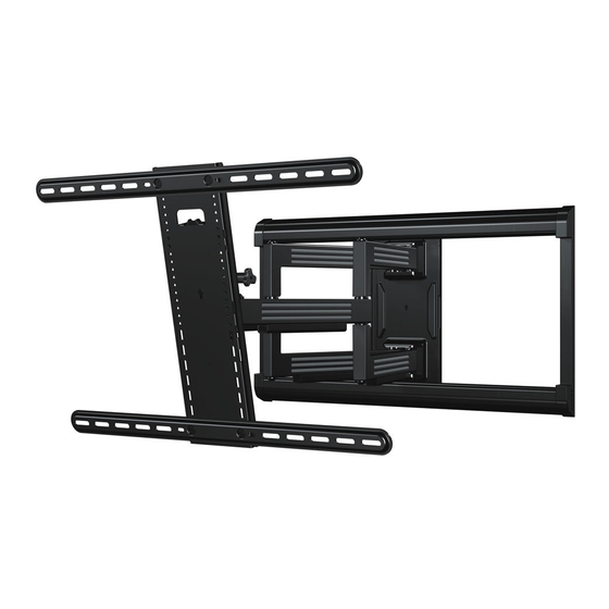
SLF 226
INSTRUCTION MANUAL
Want to watch
a video that
shows how
easy this DIY
project will be?
Watch it now at:
SANUS.com/2685
WE'RE HERE TO HELP
Recommended placement
Check it out at:
SANUS.com/1173
Get it right the
first time.
HeightFinder™
shows you
where to drill.
Call us at:
1-888-333-1376
Our US-based
install experts
are standing
by to help.
Or, chat at:
SANUS.com/chatSS
Advertisement
Table of Contents

Related Manuals for Sanus Simplicity SLF226


Summary of Contents for Sanus Simplicity SLF226
- Page 1 first time. install experts shows how HeightFinder™ are standing easy this DIY shows you by to help. project will be? where to drill. Watch it now at: Check it out at: Call us at: Or, chat at: SANUS.com/2685 SANUS.com/1173 1-888-333-1376 SANUS.com/chatSS...
-
Page 2: Important Safety Instructions
● Manufacturer is not responsible for damage or injury caused by incorrect assembly or use. If your TV (plus accessories) weighs MORE, TV Weight Limit this mount is NOT compatible. 135 lbs. (including accessories) Visit Simplicity.SANUS.com or call customer (61.2 kg) DO NOT EXCEED service to find a compatible mount. -
Page 3: Wall Construction
Wall wood studs Solid concrete or CAUTION: concrete block Construction DO NOT install ONLY install on in drywall alone these acceptable wall types. Drywall alone will hold the weight of Unsure your TV. ACCEPTABLE ACCEPTABLE Call Customer Service 888-333-1376 Tools Needed 1/2 in. - Page 4 Dimensions TV INTERFACE 23.6 [mm] 15.7 WALL PLATE TOP VIEW - EXTENDED SIDE VIEW - EXTENDED 24.0 23.6 17.7 16.0 4° UP 15° DOWN 25.8 15.2 11.5 40° - 85° 0.33 27.6 SIDE VIEW - RETRACTED FULLY ASSEMBLED MOUNT TOP VIEW - RETRACTED 27.6 17.7 15.1...
-
Page 5: Supplied Parts And Hardware
Supplied Parts and Hardware WARNING: This product contains small items that could be a choking hazard if swallowed. Before starting assembly, verify all parts are included and undamaged. If any parts are missing or damaged, do not return the damaged item to your dealer;... - Page 6 STEP 2 Parts and Hardware Lag Bolt 5/16 in. x 3 ½ in. For concrete installations ONLY (qty. 5) CAUTION Do not use in drywall or wood Concrete Anchor Washer Drilling Template (qty. 1) (qty. 5) Wall Plate (qty. 5) 5/16 in.
-
Page 7: Step 1 Attach Brackets To Tv
STEP 1 Attach Brackets to TV 1.1 Select TV Screw Diameter 1.2 Select TV Screw Length and Spacers Only one screw size fits your TV. NO SPACER SPACER NEEDED • Flat Back TV • Flat Back TV • Rounded or with Irregular Back TV Extra Space Needed... - Page 8 1. 3 Attach TV Brackets to Your TV NO SPACER SPACER NEEDED TYPICAL INSTALLATION ILLUSTRATED. Center Horizontal TV brackets over your TV's hole pattern and attach using screw combination If your TV included you selected for your TV. inset spacers or wall CAUTION: Avoid potential personal injuries and property damage! DO NOT use power tools for mount adapters, see...
- Page 9 Position the vertical TV bracket over the horizontal TV Secure the assembly with the four screws brackets and center with your TV.
-
Page 10: Wood Stud Installation
STEP 2A Attach Wall Plate Wood Stud Installation CAUTION: Avoid potential personal injury or property damage! ● Drywall covering the wall must not exceed 5/8 in. (16 mm) ● Minimum wood stud size: nominal 2 x 4 in. (51 x 102 mm) actual 1 ½ x 3 ½ in. (38 x 89 mm) ●... - Page 11 3 ½ in. (89 mm) 7/32 in. (5.5 mm) Drill pilot holes then remove the drilling template Install the wall plate using four lag bolts and washers Tighten all lag bolts only until they are pulled firmly against the wall plate. IMPORTANT: Be sure to drill into the center of the stud.
- Page 12 STEP 2B Attach Wall Plate Solid Concrete or Concrete Block Installation CAUTION: Avoid potential personal injury or property damage! ● Mount wall plate directly onto concrete surface (no wall covering) ● Minimum solid concrete thickness: 8 in. (203 mm) ● Minimum concrete block size: 8 x 8 x 16 in.
- Page 13 Remove drilling template and insert five concrete anchors Install the wall plate using five lag bolts and washers Tighten all lag bolts only until they are pulled firmly against the wall plate. CAUTION: Be sure the anchors are seated flush with the CAUTION: concrete surface.
-
Page 14: Step 3 Attach Tv To Wall Plate
STEP 3 Attach TV to Wall Plate 3.1 Attach Arm Assembly to Wall Plate Position the arm assembly on the wall plate by tilting the top Secure with four wall plate screws and washers using into the wall plate channel, then rotating the bottom toward the wall. hex key... - Page 15 3.2 Attach TV to Arm Assembly HEAVY! You may need assistance with this step. Hang your TV onto the arm assembly by first hooking the top Lock your TV to the arm assembly with locking screw CAUTION: support of vertical TV bracket , then resting the TV into place.
- Page 16 3.3 Install Cover Plates Store hex key in wall plate , for future use. NOTE: Before installing the cover plates, use the hex key to make any necessary adjustments as shown on pages 18 - 20. Bow the middle of each cover plate to slip the ends into the channels of the wall plate...
-
Page 17: Manage Cables
Manage Cables Remove the four cable covers NOTE: fully extend arms to ensure enough slack in cables. Route your cables through the arms shown — to avoid pinching. Reattach the cable covers over the cables. -
Page 18: Tilt Adjustment
TV Adjustments TILT ADJUSTMENT LEVEL ADJUSTMENT Your TV should adjust easily when moved, then stay in place. Adjust the leveling of your TV by turning the level screw If your TV is too loose or too tight, adjust the side tension knob by hand or use hex key NOTE: Once your TV is in place, tighten the tension knob prevent unwanted movement. - Page 19 LATERAL SHIFT Disconnect cables and remove your TV (PAGE 20). Reattach the four screws /washers (STEP 3.1) and Remove the cover plates and the four screws /washers replace the cover plates (STEP 3.3). from wall plate Hang your TV onto the arm assembly following STEP 3.2.
-
Page 20: Removing The Tv
REMOVING THE TV HEAVY! You may need assistance with this step. Disconnect cables. Remove screw Lift TV up and off the arm assembly... -
Page 21: Troubleshooting
Troubleshooting If you are uncertain about your hardware selection, TV Supplied Spacers contact Customer Service at 1-888-333-1376. TV SUPPLIED SPACERS Use your TV supplied spacer for: Use your TV supplied spacer and spacer for: • Flat Back TV • Rounded or Irregular Back TV with Extra Space Needed •... - Page 22 ● El fabricante no se responsabiliza de ningún daño o lesión resultante del montaje incorrecto o el uso indebido Peso máximo Si su TV (incluidos los accesorios) pesa MÁS, esta montura NO es compatible. 61,2 kg (incluidos los accesorios) Visite vuepoint.sanus.com o llame al número 1-888-333-1376 (135 lbs.) NO EXCEDAS para encontrar una montura compatible. La construcción PRECAUCIÓN: Montantes de madera Hormigón macizo o...
- Page 23 herramientas 13 mm (1/2 in.) necesarias Cinta Lápiz Nivel Cinta Destornillador Taladro Llave de métrica Adhesiva eléctrico vaso 5,5 mm 10 mm (7/32'') Localizador (3/8'') Madera Hormigón Martillo montantes Punzón Broca Broca Dimensiones VER PÁGINA 4 Piezas y accesorios suministrados VER PÁGINAS 5-6 ADVERTENCIA: Este producto contiene piezas pequeñas que, si fuesen tragadas, podrían producir asfixia.
- Page 24 ESPAÑOL 1,2 Seleccione la longitud de los tornillos para el televisor VER PÁGINA 7 SIN ESPACIADOR CON ESPACIADOR • Televisor con dorso plano • Televisor con dorso plano • Televisores con dorso plano o irregular con necesidad de espacio adicional [Los soportes del televisor se apoyan de [Los soportes del televisor...
- Page 25 ESPAÑOL PASO 2A Fijar la placa mural para montantes de madera VER PÁGINA 10 PRECAUCIÓN: Evite lesiones personales y daños materiales. ● El yeso que recubre la pared no debe exceder los 16 mm (5/8'') ● Tamaño mínimo del montante de madera: común 51 mm x 102 mm (2'' x 4'') nominal 38 mm x 89 mm (1 ½'' x 3 ½'') ●...
- Page 26 ESPAÑOL Retire la plantilla de placa mural e introduzca los anclajes para cemento PRECAUCIÓN: Cerciórese de que los anclajes queden nivelados respecto de la superficie de hormigón. Instale la placa mural usando cinco tornillos tirafondo y arandelas . Ajuste los tornillos tirafondo solamente hasta que queden firmes contra la placa mural.
- Page 27 ESPAÑOL Organizar los cables VER PÁGINA 17 1. Retire la cubierta de los cables NOTA: Extienda el brazo por completo antes de pasar los cables. 2. Pase los cables por el brazo 3. Vuelva a colocar la cubierta de los cables por sobre los cables.
- Page 28 SANUS will not be liable for any damages whatsoever arising out of the use or inability to use its products, even if SANUS has been advised of the possibility of such damages. To the maximum extent permitted by applicable law, SANUS disclaims any responsibility for incidental or consequential damages (such as the cost of repairing or replacing other property which damaged when the device does not work properly).
Need help?
Do you have a question about the Simplicity SLF226 and is the answer not in the manual?
Questions and answers
MAXIMUM WEIGHT SLF 226 CAN HOLD