Table of Contents
Advertisement
Advertisement
Table of Contents

Related Manuals for Siemens Simatic S7-1500 CPU 1512C-1 PN


Summary of Contents for Siemens Simatic S7-1500 CPU 1512C-1 PN
- Page 2 ___________________ Preface ___________________ Documentation guide ___________________ SIMATIC Product overview ___________________ Technology functions S7-1500 CPU 1512C-1 PN ___________________ (6ES7512-1CK01-0AB0) Wiring ___________________ Parameters/address space Manual ___________________ Interrupts/diagnostics alarms ___________________ Technical specifications ___________________ Dimension drawings ___________________ Parameter data records ___________________ Analog value processing 12/2017 A5E40898741-AA...
- Page 3 Note the following: WARNING Siemens products may only be used for the applications described in the catalog and in the relevant technical documentation. If products and components from other manufacturers are used, these must be recommended or approved by Siemens. Proper transport, storage, installation, assembly, commissioning, operation and maintenance are required to ensure that the products operate safely and without any problems.
-
Page 4: Preface
In order to protect plants, systems, machines and networks against cyber threats, it is necessary to implement – and continuously maintain – a holistic, state-of-the-art industrial security concept. Siemens’ products and solutions only form one element of such a concept. Customer is responsible to prevent unauthorized access to its plants, systems, machines and networks. - Page 5 This information is provided by the Siemens Industry Online Support in the Internet (https://support.industry.siemens.com). Industry Mall The Industry Mall is the catalog and order system of Siemens AG for automation and drive solutions on the basis of Totally Integrated Automation (TIA) and Totally Integrated Power (TIP).
-
Page 6: Table Of Contents
Table of contents Preface ..............................4 Documentation guide ..........................9 Product overview ..........................13 Applications of the S7-1500 CPUs..................13 Hardware properties and firmware functions ................. 20 2.2.1 Hardware properties of the CPU part ..................21 2.2.2 Firmware functions of the CPU part ..................23 2.2.3 Hardware properties of the analog on-board I/O module ............ - Page 7 Table of contents Wiring ..............................77 Supply voltage ........................77 PROFINET interfaces ......................78 Terminal and block diagrams ....................80 4.3.1 Block diagram of the CPU part ....................80 4.3.2 Terminal and block diagram of the analog on-board I/O ............81 4.3.3 Terminal and block diagram of the digital on-board I/O ............
- Page 8 Table of contents Parameter data records ........................166 Parameter assignment and structure of the parameter data records of the analog on- board I/O ..........................166 Structure of a data record for input channels of the analog on-board I/O ......166 Structure of a data record for output channels of the analog on-board I/O ......
-
Page 9: Documentation Guide
Documentation guide The documentation for the SIMATIC S7-1500 automation system and the SIMATIC ET 200MP distributed I/O system is arranged into three areas. This arrangement enables you to access the specific content you require. Basic information The System Manual and Getting Started describe in detail the configuration, installation, wiring and commissioning of the SIMATIC S7-1500 and ET 200MP systems. - Page 10 You must register once to use the full functionality of "mySupport". You can find "mySupport" on the Internet (https://support.industry.siemens.com/My/ww/en). "mySupport" - Documentation In the Documentation area in "mySupport" you can combine entire manuals or only parts of these to your own manual.
- Page 11 ● Manuals, characteristics, operating manuals, certificates ● Product master data You can find "mySupport" - CAx data on the Internet (http://support.industry.siemens.com/my/ww/en/CAxOnline). Application examples The application examples support you with various tools and examples for solving your automation tasks. Solutions are shown in interplay with multiple components in the system - separated from the focus on individual products.
- Page 12 You can find the SIMATIC Automation Tool on the Internet (https://support.industry.siemens.com/cs/ww/en/view/98161300). PRONETA With SIEMENS PRONETA (PROFINET network analysis), you analyze the PROFINET network during commissioning. PRONETA features two core functions: ● The topology overview independently scans PROFINET network and all connected components.
-
Page 13: Product Overview
Product overview Applications of the S7-1500 CPUs Application area The SIMATIC S7-1500 is the modular control system for numerous automation applications in discrete automation. The modular and fanless design, the simple implementation of distributed structures and the user-friendly handling transform the SIMATIC S7-1500 into a cost-effective and convenient solution for various tasks. - Page 14 Product overview 2.1 Applications of the S7-1500 CPUs Performance segments of the standard, compact, fail-safe and technology CPUs The CPUs can be used for smaller and medium-sized applications, as well as for the high- end range of machine and plant automation. Table 2- 1 Standard CPUs Performance segment...
- Page 15 Product overview 2.1 Applications of the S7-1500 CPUs Performance segment PROFIBUS PROFINET PROFINET PROFINET Work memory Pro- interfaces IO RT/IRT IO RT basic func- cessing interfaces interface tionality time for bit operations CPU 1513F-1 PN Fail-safe CPU for medium- 1.95 MB 40 ns sized applications CPU 1515F-2 PN...
- Page 16 Product overview 2.1 Applications of the S7-1500 CPUs Performance segments of compact CPUs The compact CPUs can be used for smaller to medium-sized applications and have an integrated analog and digital on-board I/O as well as integrated technology functions. The following table shows the differences in performance between the two compact CPUs.
- Page 17 Product overview 2.1 Applications of the S7-1500 CPUs Integrated Motion Control technology functions All CPUs of SIMATIC S7-1500 support Motion Control technology functions. STEP 7 offers Motion Control instructions standardized according to PLCopen for configuring and connecting a drive to the CPU. S7-1500 Motion Control supports the following technology objects: ●...
- Page 18 Product overview 2.1 Applications of the S7-1500 CPUs Other technology functions Technology modules also implement functions such as high-speed counting, position detection, measuring functions and pulse generators (PTO, PWM and frequency output). For compact CPU 1511C-1 PN and CPU 1512C-1 PN CPUs, these functions are already integrated and can be implemented without additional technology modules.
- Page 19 Detailed information about this and a multitude of other display functions is available in the SIMATIC S7-1500 Display Simulator (http://www.automation.siemens.com/salesmaterial-as/interactive-manuals/getting- started_simatic-s7-1500/disp_tool/start_en.html). Uniform front connectors for all modules and integrated potential jumpers for flexible formation of potential groups simplifies storage.
-
Page 20: Hardware Properties And Firmware Functions
● 3 x shield terminal ● 3 x infeed element (push-in terminals) ● 3 x labeling strip ● 3 x universal front cover For more information on accessories, refer to the S7-1500, ET 200MP system manual (http://support.automation.siemens.com/WW/view/en/59191792). CPU 1512C-1 PN (6ES7512-1CK01-0AB0) Manual, 12/2017, A5E40898741-AA... -
Page 21: Hardware Properties Of The Cpu Part
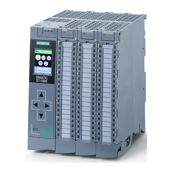
Product overview 2.2 Hardware properties and firmware functions 2.2.1 Hardware properties of the CPU part View of the CPU The figure below shows the CPU part of the CPU 1512C-1 PN. Figure 2-1 CPU 1512C-1 PN Note Protective film Note that a protective film is attached to the display of the CPU when shipped from the factory. - Page 22 SIMATIC S7-1500 Display Simu- • carry out further network settings. The display shows lator occurring error messages directly in plain text. (http://www.automation.siemens. In addition to the functions listed here, a multitude of com/salesmaterial-as/interactive- other functions that are described in the SIMATIC S7- manuals/getting-started_simatic- 1500 Display Simulator are shown on the display.
-
Page 23: Firmware Functions Of The Cpu Part
The system automatically generates the messages for Diagnostics function manual nostics the system diagnostics and outputs these messages (http://support.automation.siemens.c via a programming device/PC, HMI device, the Web om/WW/view/en/59192926) server or the integrated display. System diagnostics information is also available when the CPU is in STOP mode. - Page 24 PROFINET IO RT (real time) RT prioritizes PROFINET IO telegrams over standard PROFINET function manual telegrams. This ensures the required determinism in (http://support.automation.siemens.c the automation technology. In this process the data is om/WW/view/en/49948856) transferred via prioritized Ethernet telegrams. IRT (isochronous real...
- Page 25 Integrated closed-loop PID control function manual PID Compact (continuous PID controller) • control functionality (https://support.industry.siemens.co PID 3Step (step controller for integrating actuators) • m/cs/ww/en/view/108210036) PID Temp (temperature controller for heating and • cooling with two separate actuators)
- Page 26 Know-how protection The know-how protection protects user blocks against S7-1500, ET 200MP system manual unauthorized access and modifications. (http://support.automation.siemens.c om/WW/view/en/59191792) Copy protection Copy protection links user blocks to the serial number of the SIMATIC memory card or to the serial number of the CPU.
-
Page 27: Hardware Properties Of The Analog On-Board I/O Module
Product overview 2.2 Hardware properties and firmware functions 2.2.3 Hardware properties of the analog on-board I/O module View The following figure shows the analog on-board I/O (X10) of the CPU 1512C-1 PN. Figure 2-2 Analog on-board I/O CPU 1512C-1 PN (6ES7512-1CK01-0AB0) Manual, 12/2017, A5E40898741-AA... - Page 28 Product overview 2.2 Hardware properties and firmware functions Properties of the analog inputs The 5 inputs of the analog on-board I/O module have the following properties: Property Description Additional information Resolution: 16 bits includ- A CPU processes information exclusively in digital Chapter Analog value pro- •...
- Page 29 Product overview 2.2 Hardware properties and firmware functions Properties of the analog outputs The 2 outputs of the analog on-board I/O module have the following properties: Property Description Additional information Resolution: 16 bits includ- Once the CPU has processed the digital signal, a DAC Chapter Analog value pro- •...
-
Page 30: Firmware Functions Of The Analog On-Board I/O Module
Product overview 2.2 Hardware properties and firmware functions 2.2.4 Firmware functions of the analog on-board I/O module Functions of the analog inputs The 5 inputs of the analog on-board I/O module have the following functions: Function Description Additional information Reconfiguration in RUN You have the option of reassigning parameters for the Chapter Parameters of the ana- •... -
Page 31: Hardware Properties Of The Digital On-Board I/O Module
Product overview 2.2 Hardware properties and firmware functions 2.2.5 Hardware properties of the digital on-board I/O module View The following figure shows the digital on-board I/O (X11 and X12) of the CPU 1512C-1 PN. Figure 2-3 Digital on-board I/O CPU 1512C-1 PN (6ES7512-1CK01-0AB0) Manual, 12/2017, A5E40898741-AA... - Page 32 Product overview 2.2 Hardware properties and firmware functions Properties of the digital inputs The digital inputs of the digital on-board I/O module have the following properties: Property Description Additional information Standard and high-speed The digital on-board I/O module has 32 high-speed Section Wiring (Page 77) inputs inputs for signals up to a max.
- Page 33 Product overview 2.2 Hardware properties and firmware functions Property Description Additional information Application The outputs are suitable for, e.g. solenoid valves, DC contactors and indicator lights, or also for signal trans- mission or proportional valves. Driver blocks X11 The digital outputs of the digital onboard I/O X11 have Section Terminal and block diagram driver blocks with parasitic diodes.
-
Page 34: Firmware Functions Of The Digital On-Board I/O Module
Product overview 2.2 Hardware properties and firmware functions 2.2.6 Firmware functions of the digital on-board I/O module Functions of the digital inputs The digital inputs of the digital on-board I/O module have the following functions: Function Description Additional information Technology functions The high-speed digital inputs of the digital on-board Chapter Technology functions I/O module support technology functions such as fast... - Page 35 Product overview 2.2 Hardware properties and firmware functions Functions of the digital outputs The digital outputs of the digital on-board I/O module have the following functions: Function Description Additional information Technology functions The high-speed digital outputs of the digital on-board Chapter Technology functions I/O module support technology functions such as fast (Page 42)
-
Page 36: Operator Controls And Display Elements
Product overview 2.3 Operator controls and display elements Operator controls and display elements 2.3.1 Front view with closed front panel The following figure shows the front view of the CPU 1512C-1 PN. ① LEDs for the current operating mode and diagnostics status of the CPU ②... - Page 37 (local lock) and assign a password for the display. For more information on the display, the configurable protection levels and the local lock, refer to the S7-1500, ET 200MP (http://support.automation.siemens.com/WW/view/en/59191792) system manual. Reference You will find detailed information on the individual display options, a training course and a simulation of the available menu commands in the SIMATIC S7-1500 Display Simulator (http://www.automation.siemens.com/salesmaterial-as/interactive-manuals/getting-...
-
Page 38: Front View Of The Cpu Without Front Panel And View From Below
Product overview 2.3 Operator controls and display elements 2.3.2 Front view of the CPU without front panel and view from below The following figure shows the operator control and connection elements of the CPU 1512C-1 PN with the front cover of the CPU open. ①... - Page 39 Product overview 2.3 Operator controls and display elements ① Slot for the SIMATIC memory card ② PROFINET IO interface (X1) with 2 ports ③ Connection for supply voltage ④ Fastening screw Figure 2-7 View of the CPU 1512C-1 PN – bottom CPU 1512C-1 PN (6ES7512-1CK01-0AB0) Manual, 12/2017, A5E40898741-AA...
-
Page 40: Rear View
Product overview 2.3 Operator controls and display elements 2.3.3 Rear view The following figure shows the connection elements on the rear of the CPU 1512C-1 PN. ① Shield contact surfaces ② Plug-in connection for power supply ③ Plug-in connection for backplane bus ④... -
Page 41: Operating Mode Buttons
You can find additional information in the up yellow. memory card): S7-1500/ET 200MP system manual 2. Press the operating mode button (https://support.industry.siemens.com/cs/ww/en/vi STOP until the RUN/STOP LED ew/59191792). lights up for the 2nd time and re- mains continuously lit (this takes three seconds). -
Page 42: Technology Functions
Technology functions High-speed counters Properties The technology functions of the compact CPU have the following technical properties: ● 32 high-speed digital inputs (up to 100 kHz), isolated – 6 high-speed counters (High Speed Counter/HSC), which can all be used as A/B/N ●... -
Page 43: Functions
Technology functions 3.1 High-speed counters 3.1.1 Functions 3.1.1.1 Counting Counting refers to the detection and adding up of events. The counters acquire and evaluate encoder signals and pulses. You can specify the count direction using encoder or pulse signals or through the user program. You can control counting processes using the digital inputs. -
Page 44: Measuring
The hysteresis prevents these unwanted switching operations. Reference For more information on the counter, refer to the S7-1500, ET 200MP, ET 200SP Counting, measurement and position detection function manual (http://support.automation.siemens.com/WW/view/en/59709820). 3.1.1.2 Measuring Measuring functions The following measuring functions are available:... -
Page 45: Position Detection For Motion Control
For a detailed description of the use of motion control and its configuration, refer to the S7- 1500 Motion Control function manual (http://support.automation.siemens.com/WW/view/en/109749262). In the function module, the interface between the drives and encoders is referred to as a technology module (TM). In this context, a technology module (TM) also refers to the digital on-board I/O of the compact CPU described here. -
Page 46: Additional Functions
Technology functions 3.1 High-speed counters 3.1.1.4 Additional functions Synchronization You can configure an external reference signal edge to load the counter with the specified start value. The following external signals can trigger a synchronization: ● Rising or falling edge of a digital input ●... -
Page 47: Configuring The High-Speed Counters
> Counting, measuring and position detection (S7-1500)" A detailed description of configuring Motion Control be found in: ● S7-1500 Motion Control (http://support.automation.siemens.com/WW/view/en/59381279) function manual ● in the STEP 7 online help under "Using technology functions > Motion Control > Motion Control (S7-1500)"... - Page 48 Technology functions 3.1 High-speed counters Control interface per channel The following table shows the control interface assignment: Table 3- 3 Assignment of the control interface Offset from start Parameter Meaning address Bytes 0 to 3 Slot 0 Load value (meaning of the value is specified in LD_SLOT_0) Bytes 4 to 7 Slot 1 Load value (meaning of the value is specified in LD_SLOT_1)
- Page 49 Technology functions 3.1 High-speed counters Offset from start Parameter Meaning address Byte 10 SET_DIR Bit 7: Count direction (with encoder without direction signal) – Bits 2 to 6: Reserve; bits must be set to 0 RES_EVENT Bit 1: Reset of saved events RES_ERROR Bit 0: Reset of saved error states Byte 11...
-
Page 50: Assignment Of The Feedback Interface Of The High-Speed Counters
For information on configuring the technology object and programming the associated instruction, refer to the S7-1500, ET 200MP, ET 200SP Counting, measurement and position detection (http://support.automation.siemens.com/WW/view/en/59709820) function manual. Feedback interface per channel The following table shows the feedback interface assignment:... -
Page 51: Pulse Generators
Technology functions 3.2 Pulse generators Offset from start Parameter Meaning address Byte 15 STS_M_INTERVAL Bit 7: Count pulse detected in previous measuring interval EVENT_CAP Bit 6: Capture event has occurred EVENT_SYNC Bit 5: Synchronization has occurred EVENT_CMP1 Bit 4: Comparison event for DQ1 has occurred EVENT_CMP0 Bit 3: Comparison event for DQ0 has occurred EVENT_OFLW... - Page 52 Technology functions 3.2 Pulse generators Principle of operation With pulse width modulation, a signal with defined cycle duration and variable on-load factor is output at the digital output. The on-load factor is the relationship of the pulse duration to the cycle duration. In PWM mode, you can control the on-load factor and the cycle duration. With pulse width modulation you vary the mean value of the output voltage.
- Page 53 Technology functions 3.2 Pulse generators Controller For the pulse width modulation (PWM) mode, the user program directly accesses the control and feedback interface of the channel. A reconfiguration via the instructions WRREC/RDREC and parameter assignment data record 128 is supported. You can find additional information in section Parameter data records (PWM) (Page 187) You control the on-load factor (pulse cycle ratio) of the pulse width via the OUTPUT_VALUE...
- Page 54 Technology functions 3.2 Pulse generators Canceling the output sequence A deactivation of the software enable (SW_ENABLE = 1 → 0) cancels the current output sequence. The last cycle duration is not completed. STS_ENABLE and the digital output PWM DQA are immediately reset to 0. A renewed pulse output is only possible after a restart of the output sequence.
- Page 55 Technology functions 3.2 Pulse generators Setting and changing the pulse on-load factor OUTPUT_VALUE assigns the on-load factor for the current period duration. You select the range of the field OUTPUT_VALUE of the control interface with the "Output format" parameter. ● Output format per 100: Value range between 0 and 100 Pulse duration = (OUTPUT_VALUE/100) x period duration.
- Page 56 Technology functions 3.2 Pulse generators Setting the minimum pulse duration and the minimum interpulse period You assign the minimum pulse duration and the minimum interpulse period as DWORD numerical value between 0 and 10 000 000 μs (10 s) with the help of the channel parameter configuration "Minimum pulse duration".
- Page 57 Technology functions 3.2 Pulse generators Category Parameter Meaning Value range Default Output format Defines the format of the ratio S7 analog output Per 100 value (on-load factor) in the field Interprets the ratio value in the "OUTPUT_VALUE" of the control field OUTPUT_VALUE"...
-
Page 58: Operating Mode: Frequency Output
Technology functions 3.2 Pulse generators Category Parameter Meaning Value range Default Hardware Pulse output The parameter "Pulse output For B: Hardware inputs / (DQA) (DQA)" defines the hardware out- X11, terminal 21 (DQ0 / %Q4.0): output for the outputs put to use as pulse output chan- 10 kHz / 0.5 A or 100 kHz / 0.1 A least signifi- nel. - Page 59 Technology functions 3.2 Pulse generators Controller For the frequency output mode, the user program directly accesses the control and feedback interface of the channel. A reconfiguration via the instructions WRREC/RDREC and parameter assignment data record 128 is supported. You can find additional information in section Parameter data records (PWM) (Page 187).
- Page 60 Technology functions 3.2 Pulse generators Setting and changing the output value (frequency) You set the frequency with the OUTPUT_VALUE directly with the control program in the control interface. The value is specified in the real format and the unit is always "Hz". The possible range depends on the parameter "High-speed output (0.1 A)"...
- Page 61 Technology functions 3.2 Pulse generators Category Parameter Meaning Value range Default Diagnostics No supply voltage The parameter "No supply voltage Deactivated Deactivated interrupt L+" activates the diagnostic inter- rupt of the channel in the case of Activated no supply voltage L+ Parameter High-speed output The "High-speed output (0.1 A)"...
-
Page 62: Operating Mode: Pto
Technology functions 3.2 Pulse generators 3.2.1.3 Operating mode: PTO The PTO (Pulse Train Output) mode can be used to output position information. This allows you to, for example, control stepper motor drives or simulate an incremental encoder. The frequency of the pulses represents the speed, while the number of pulses represents the distance. - Page 63 Technology functions 3.2 Pulse generators ● PTO (A, B phase-shifted): When you select the PTO signal type (A, B phase-shifted), the two outputs pulses with the specified velocity, but phase-shifted by 90 degrees. This is a 1x combination in which the pulse shows the duration between two positive transitions of A.
- Page 64 Technology functions 3.2 Pulse generators Parameters of PTO mode Category Parameter Meaning Value range Default Diagnostics No supply voltage L+ With the parameter "No Deactivated Deactivated interrupt supply voltage L+" you Activated activate the diagnostic interrupt of the channel in the case of no supply voltage L+.
- Page 65 Technology functions 3.2 Pulse generators Category Parameter Meaning Value range Default Increments per revolu- The "Increments per 1 to 1,000,000 tion revolution" is used to define the number of increments per revolu- tion (also in microstep mode), which is re- quired by the drive for a revolution.
- Page 66 PROFIdrive interface "Telegram 3". For a detailed description of the use of motion control and its configuration, refer to the S7-1500 Motion Control function manual (http://support.automation.siemens.com/WW/view/en/109749262) and the STEP 7 online help. CPU 1512C-1 PN (6ES7512-1CK01-0AB0)
-
Page 67: Functions
Technology functions 3.2 Pulse generators 3.2.2 Functions 3.2.2.1 Function: High-speed output The function "High-speed output (0.1 A)" enhances the signal clock of the digital outputs (DQ0 to DQ7). Less delay, fluctuation, jitter, and shorter rise and fall times, occur at the switching edges. -
Page 68: Function: Direct Control Of The Pulse Output (Dqa)
Technology functions 3.2 Pulse generators 3.2.2.2 Function: Direct control of the pulse output (DQA) Direct control of the pulse output (DQA) In the modes "Pulse width modulation PWM" and "Frequency output", you can set the pulse output (DQA) of a pulse generator directly via the control program. Select the function for the DQ direct control by deleting the output control bit of the PWM channel (TM_CTRL_DQ = 0) in the control interface. -
Page 69: Configuring The Pwm And Frequency Output Modes
Technology functions 3.2 Pulse generators 3.2.3 Configuring the PWM and frequency output modes 3.2.3.1 Assignment of the control interface The user program influences the behavior of the PWM channel through the control interface. Control interface per channel The following table shows the control interface assignment: Table 3- 5 Assignment of the control interface Byte 0... - Page 70 Technology functions 3.2 Pulse generators Use case 1. Transfer the control for the output to the PWM channel. 2. Set SW_ENABLE, in order that the output can be started. 3. Set the required on-load factor using OUTPUT_VALUE. 4. If necessary, change the period duration (cyclic or once). If you do not change the value, the period duration from the hardware configuration will be used.
-
Page 71: Handling The Slot Parameter (Control Interface)
Technology functions 3.2 Pulse generators 3.2.3.2 Handling the SLOT parameter (control interface) SLOT and MODE_SLOT SLOT has the following operating modes. ● Mode for individual update (MODE_SLOT = 0) Use this mode if you occasionally change the specific parameters (such as period duration) before the start of the output sequence or during operation. - Page 72 Technology functions 3.2 Pulse generators Interpretation of the SLOT parameter value The value written in the SLOT parameter is displayed as in the table below depending on the LD_SLOT value and the mode is interpreted. LD_SLOT Meaning of SLOT value Valid modes for using the SLOT SLOT data type value...
- Page 73 Technology functions 3.2 Pulse generators Individual updating of the parameter 'Period duration' The following representation illustrates the workflow of the individual updating of the parameter 'Period duration'. The described workflow principle can also be used on the channels of the high-speed counters. ①...
- Page 74 Technology functions 3.2 Pulse generators Cyclic updating of the parameter 'Period duration' The following representation illustrates the execution of the cyclic updating of the parameter 'Period duration'. The described workflow principle can also be used on the channels of the high-speed counters.
-
Page 75: Assignment Of The Feedback Interface
Technology functions 3.2 Pulse generators 3.2.3.3 Assignment of the feedback interface The user program receives current values and status information from the pulse width modulation via the feedback interface. Feedback interface per channel The following table shows the feedback interface assignment: Table 3- 6 Assignment of the feedback interface Byte 0... - Page 76 Technology functions 3.2 Pulse generators Feedback parameters Table 3- 7 Status feedback Feedback parameters Meaning Value range STS_READY The channel is correctly configured, is operating 0: Not ready to run and supplying valid data. 1: Ready to run STS_SW_ENABLE Current status of the software enable 0: SW_ENABLE is not active 1: SW_ENABLE detected STS_LD_SLOT...
-
Page 77: Wiring
Wiring Supply voltage 24 V DC supply voltage (X80) The connecting plug for the supply voltage is plugged in when the CPU ships from the factory. The following table shows the terminal assignment for a 24 V DC power supply. ①... -
Page 78: Profinet Interfaces
You need a screwdriver (max. blade width 2.5 mm) to remove the PROFINET plug. Reference For more information on "Wiring the CPU" and "Accessories/spare parts", refer to the S7- 1500, ET 200MP system manual (http://support.automation.siemens.com/WW/view/en/59191792). CPU 1512C-1 PN (6ES7512-1CK01-0AB0) Manual, 12/2017, A5E40898741-AA... - Page 79 Wiring 4.2 PROFINET interfaces Assignment of the MAC addresses The CPU 1512C-1 PN has a PROFINET interface with two ports. The PROFINET interface itself has a MAC address, and each of the two PROFINET ports has its own MAC address. The CPU 1512C-1 PN therefore has three MAC addresses in total.
-
Page 80: Terminal And Block Diagrams
Wiring 4.3 Terminal and block diagrams Terminal and block diagrams 4.3.1 Block diagram of the CPU part Block diagram The following figure shows the block diagram of the CPU part. ① CPU with control and operating mode PN X1 P1 R PROFINET interface X1 port 1 buttons ②... -
Page 81: Terminal And Block Diagram Of The Analog On-Board I/O
This section contains the block diagram of the analog on-board I/O (X10) and various wiring options. For information on wiring the front connector, establishing the cable shield, etc., refer to the S7-1500, ET 200MP (http://support.automation.siemens.com/WW/view/en/59191792) system manual. Note You can use and combine the different wiring options for all channels. Note, however, that unneeded terminals of an analog input channel must not be connected. - Page 82 Wiring 4.3 Terminal and block diagrams Wiring: Voltage measurement The following figure shows the terminal assignment for voltage measurement at the channels available for this measurement type (channels 0 to 3). ① Analog-to-digital converter (ADC) ② LED interface ③ Infeed element (for shielding only) ④...
- Page 83 Wiring 4.3 Terminal and block diagrams Wiring: 4-wire measuring transducer for current measurement The following figure shows the terminal assignment for current measurement with 4-wire measuring transducer at the channels available for this measurement type (channels 0 to 3). ① Analog-to-digital converter (ADC) ②...
- Page 84 Wiring 4.3 Terminal and block diagrams Wiring: 2-wire measuring transducer for current measurement Alternatively to connecting a 4-wire transducer, you can also connect 2-wire transducers to channels 0 to 3. An external 24 V power supply is required to connect a 2-wire transducer to the analog on-board I/O of the compact CPU.
- Page 85 Wiring 4.3 Terminal and block diagrams Wiring: 4-wire connection of resistance-type sensors or thermal resistors (RTD) The following figure shows the terminal assignment for 4-wire connection of resistance-type sensors or thermal resistors at the channel available for this (channel 4). ①...
- Page 86 Wiring 4.3 Terminal and block diagrams Wiring: 3-wire connection of resistance-type sensors or thermal resistors (RTD) The following figure shows the terminal assignment for 3-wire connection of resistance-type sensors or thermal resistors at the channel available for this (channel 4). Note 3-wire connection Note that line resistances are not compensated with a 3-wire connection.
- Page 87 Wiring 4.3 Terminal and block diagrams Wiring: 2-wire connection of resistance-type sensors or thermal resistors (RTD) The following figure shows the terminal assignment for 2-wire connection of resistance-type sensors or thermal resistors at the channel available for this (channel 4). Note 2-wire connection Note that line resistances are not compensated with a 2-wire connection.
- Page 88 Wiring 4.3 Terminal and block diagrams Wiring: Voltage output The figure below shows the terminal assignment for the wiring of the voltage outputs with: ● 2-wire connection, no compensation for line resistances. ① Analog-to-digital converter (ADC) ② LED interface ③ Infeed element (for shielding only) ④...
- Page 89 Wiring 4.3 Terminal and block diagrams Wiring: Current output The following figure shows an example of the terminal assignment for wiring current outputs. ① Analog-to-digital converter (ADC) ② LED interface ③ Infeed element (for shielding only) ④ Digital-to-analog converter (DAC) ⑤...
-
Page 90: Terminal And Block Diagram Of The Digital On-Board I/O
For information on wiring the front connector, establishing the cable shield, etc., refer to the S7-1500, ET 200MP (http://support.automation.siemens.com/WW/view/en/59191792) system manual. Infeed element The infeed element is inserted on the front connector and serves to shield the digital on- board I/O. - Page 91 Wiring 4.3 Terminal and block diagrams Block diagram and terminal assignment X11 The figure below shows you how to connect the digital on-board I/O X11 and the assignment of the channels to the addresses (input byte a and b, output byte c and d). ①...
- Page 92 Wiring 4.3 Terminal and block diagrams Block diagram and terminal assignment X12 The figure below shows you how to connect the digital on-board I/O X12 and the assignment of the channels to the addresses (input byte a and b, output byte c and d). ①...
- Page 93 Wiring 4.3 Terminal and block diagrams Supply voltage using the digital on-board I/O X11 as an example The inputs and outputs of the digital on-board I/O are divided into two load groups, which are supplied with 24 V DC. The digital inputs DI0 to DI15 form a load group and are supplied via the connections 1L+ (terminal 19) and 1M (terminal 20).
- Page 94 Wiring 4.3 Terminal and block diagrams As a supplement to the block diagram and terminal assignment, the following figure shows the correct wiring of the outputs in order to prevent switching of the outputs in the event of a ground wire break. Figure 4-14 Correct wiring using the digital on-board I/O X11 as an example The ground is supplied with a first cable from the central terminal block to terminal 30 of the...
- Page 95 Wiring 4.3 Terminal and block diagrams The figure below shows the current flow with correct wiring. Figure 4-15 Current flow with correct wiring using the digital on-board I/O X11 as an example With correct wiring, the supply current flows from the power supply 2L+ via terminal 29 to the module.
- Page 96 Wiring 4.3 Terminal and block diagrams The figure below shows the reaction to interruption of the first ground cable. Figure 4-16 Interruption of the first ground cable using the digital on-board I/O X11 as an example If a wire break occurs on the first ground cable from the central terminal block to terminal 30, the module can continue to operate without restrictions, as it is still connected to the ground via the second cable from the central terminal block to terminal 40.
- Page 97 Wiring 4.3 Terminal and block diagrams The figure below shows the reaction to interruption of the second ground cable. Figure 4-17 Interruption of the second ground cable using the digital on-board I/O X11 as an example If a wire break occurs on the second ground cable from the central block terminal to terminal 30, the module can continue to operate without restrictions, as it is still connected to the ground via the first cable from the central terminal block to terminal 40.
- Page 98 Wiring 4.3 Terminal and block diagrams The figure below shows the current flow upon interruption of both ground cables. Figure 4-18 Current flow upon interruption of both ground cables using the digital on-board I/O X11 as an example If a wire break occurs on the first and on the second ground cable from the central terminal block to the terminals 30 and 40 of the module, a malfunction occurs on the module.
- Page 99 Wiring 4.3 Terminal and block diagrams Faulty wiring The following figure shows faulty wiring, which has a bridge on the front connector. Figure 4-19 Faulty wiring using the digital on-board I/O X11 as an example: Bridge Terminals 30 and 40 are connected in the front connector and only routed with one cable to the central terminal block.
- Page 100 Wiring 4.3 Terminal and block diagrams The figure below shows the current flow when the ground connections of the loads and the ground connection of terminal 30 are routed with a common cable to the central terminal block. ① Ground connections of other plant parts that can also carry large currents. Figure 4-20 Faulty wiring using the digital on-board I/O X11 as an example: Common cable If a break occurs in the common cable, the current of the outputs flows via terminal 30 to the...
- Page 101 Wiring 4.3 Terminal and block diagrams The figure below shows the current flow with correct wiring when a potential difference exits between the grounding points. ① Grounding point functional earth 1 (FE 1) ② Grounding point functional earth 2 (FE 2) Figure 4-21 Potential difference using the digital on-board I/O X11 as an example Equipotential bonding occurs via terminals 30 and 40.
- Page 102 Wiring 4.3 Terminal and block diagrams Response of the digital outputs to a wire break at ground connection of the outputs (X12) Due to the design of the module, in contrast to the digital onboard I/O X12, no supply current is discharged via the outputs if ground is interrupted in the digital onboard I/O X12, in contrast to the digital onboard I/O X11.
- Page 103 Wiring 4.3 Terminal and block diagrams Input filter for digital inputs To suppress disruptions, you can configure an input delay for the digital inputs. You can specify the following values for the input delay: ● None ● 0.05 ms ● 0.1 ms ●...
-
Page 104: Addresses Of The High-Speed Counters
40-pin front connectors of the digital on-board I/O. For information on wiring the front connectors, establishing the cable shields, etc., refer to the S7-1500, ET 200MP (http://support.automation.siemens.com/WW/view/en/59191792) system manual. Encoder signals The 24 V encoder signals are designated with letters A, B and N. You can connect the following encoder types: ●... - Page 105 Wiring 4.3 Terminal and block diagrams Digital inputs HSC DI0 and HSC DI1 The digital inputs are logically assigned to the high-speed counters (HSC). For information on the possible assignment of the on-board I/O inputs to the high-speed counters, refer to table Interconnection overview of the inputs (Page 109).
- Page 106 Reference For more information on configuring the inputs of the high-speed counters, refer to the S7-1500, ET 200MP, ET 200SP Counting, measurement and position detection (http://support.automation.siemens.com/WW/view/en/59709820) function manual and the STEP 7 online help. CPU 1512C-1 PN (6ES7512-1CK01-0AB0) Manual, 12/2017, A5E40898741-AA...
-
Page 107: Addresses Of The Pulse Generators In The Pulse Width Modulation (Pwm) And Frequency Output Modes
TM_CTRL_DQ to 0 and switch the output on or off with the bit SET_DQA (relevant for the PWM and Frequency Output modes). For more information on forcing inputs and outputs, refer to the S7-1500, ET 200MP system manual (http://support.automation.siemens.com/WW/view/en/59191792). CPU 1512C-1 PN (6ES7512-1CK01-0AB0) Manual, 12/2017, A5E40898741-AA... -
Page 108: Addresses Of Pulse Generators In The Pto Mode
40-pin front connectors of the digital on-board I/O. For information on wiring the front connectors and establishing the cable shield, refer to the S7-1500, ET 200MP system manual (http://support.automation.siemens.com/WW/view/en/59191792). Encoder signals In addition to supporting its outputs, each PTO channel also supports the three following optional inputs: ●... -
Page 109: Interconnection Overview Of The Inputs
Wiring 4.3 Terminal and block diagrams 4.3.7 Interconnection overview of the inputs Combined interconnection of the technology channels In order that you can correctly divide the available inputs between the possible technology channels HSC and PTO, the following table provides you with an overview of the possible interconnections of the front connectors X11 and X12. - Page 110 Wiring 4.3 Terminal and block diagrams Termi- Chan- High-speed counter (HSC) PTO1 PTO2 PTO3 PTO4 HSC4 HSC5 HSC6 nect [DR] [DR] [DR] [DR] [DR] [DR] [DR] [DR] [DR] [DR] [DR] [DR] [DR] [DR] [DR] [DR] [DR] [DR] [DR] [DR] [DR] [DR] [DR] [DR]...
-
Page 111: Interconnection Overview Of Outputs
Wiring 4.3 Terminal and block diagrams 4.3.8 Interconnection overview of outputs Combined interconnection of the technology channels The following table provides you with an overview of the possible interconnections of the front connectors X11 and X12 to allow you to correctly divide the available inputs between the possible technology channels HSC, PWM and PTO. - Page 112 Wiring 4.3 Terminal and block diagrams [PTO 1/2/3/4] [PTO 1/2/3/4] [PTO 1/2/3/4] [PTO 1/2/3/4] [PTO 1/2/3/4] [PTO Standard 1/2/3/4] [PTO 1/2/3/4] [PTO 1/2/3/4] [PTO 1/2/3/4] [PTO 1/2/3/4] DQ10 [PTO 1/2/3/4] DQ11 [PTO 1/2/3/4] DQ12 [PTO 1/2/3/4] DQ13 [PTO 1/2/3/4] DQ14 [PTO 1/2/3/4] DQ15...
- Page 113 Wiring 4.3 Terminal and block diagrams Technical characteristics of the outputs The following table shows an overview of the technical characteristics of the individual outputs. Frequency range DQ0 to DQ7 DQ8 to DQ15 (period duration) High-speed output High-Speed output Standard output (0.1 A) activated (0.1 A) deactivated max.
-
Page 114: Parameters/Address Space
Parameters/address space Address space of the analog on-board I/O Address space of the analog input and output channels The addresses are divided into five analog input channels and two analog output channels. STEP 7 (TIA Portal) assigns the addresses automatically. You can change the addresses in the hardware configuration of STEP 7 (TIA Portal), i.e. - Page 115 Parameters/address space 5.1 Address space of the analog on-board I/O Value status (quality information, QI) As of firmware version 2.0, the analog and digital on-board I/O support the value status as diagnostics option. You activate the use of the value status in the hardware configuration of STEP 7 (TIA Portal).
-
Page 116: Address Space Of The Digital On-Board I/O
Parameters/address space 5.2 Address space of the digital on-board I/O Address space of the digital on-board I/O Address space of digital input and digital output channels The addresses are divided into 2 x 16 digital input channels and 2 x 16 digital output channels. - Page 117 Parameters/address space 5.2 Address space of the digital on-board I/O Figure 5-3 Address space of the submodule X12 of the 2 x 32-channel digital on-board I/O (16 digital inputs/16 digital outputs) with value status CPU 1512C-1 PN (6ES7512-1CK01-0AB0) Manual, 12/2017, A5E40898741-AA...
- Page 118 Parameters/address space 5.2 Address space of the digital on-board I/O Value status (quality information, QI) As of firmware version 2.0, the analog and digital on-board I/O support the value status as diagnostics option. You activate the use of the value status in the hardware configuration of STEP 7 (TIA Portal).
-
Page 119: Address Space Of The Pulse Generators
Parameters/address space 5.3 Address space of the pulse generators Address space of the high-speed counters Table 5- 1 Size of the input and output addresses of the high-speed counters Inputs Outputs Size per high-speed counter (6x) 16 bytes 12 bytes You can find a description of the control interface in the section Assignment of the control interface of the high-speed counters (Page 47). -
Page 120: Measurement Types And Measuring Ranges Of The Analog On-Board I/O
Parameters/address space 5.4 Measurement types and measuring ranges of the analog on-board I/O Measurement types and measuring ranges of the analog on- board I/O Introduction The analog on-board I/O is set to voltage measurement type and measuring range ±10 V by default for the inputs on channels 0 to 3. -
Page 121: Output Type And Output Ranges Of The Analog On-Board I/O
Parameters/address space 5.5 Output type and output ranges of the analog on-board I/O Output type and output ranges of the analog on-board I/O Introduction The analog on-board I/O is set to voltage output type and output range ±10 V as default for the outputs. -
Page 122: Parameters Of The Analog On-Board I/O
Parameters/address space 5.6 Parameters of the analog on-board I/O Parameters of the analog on-board I/O Parameters of the analog on-board I/O You specify the properties of the analog on-board I/O during parameter assignment with STEP 7 (TIA Portal). The tables below list the parameters that can be set for inputs and outputs, respectively. - Page 123 Parameters/address space 5.6 Parameters of the analog on-board I/O Table 5- 6 Configurable "Measuring" parameters Parameters Value range Default Reconfiguration in RUN Measuring See section Measurement Voltage Measurement type • types and measuring ranges (channels 0 to 3) of the analog on-board I/O Resistance (Page 120) (channel 4)
- Page 124 Parameters/address space 5.6 Parameters of the analog on-board I/O Configurable parameters and default settings for outputs Table 5- 8 Configurable "Diagnostics" parameters Parameters Value range Default Reconfiguration in RUN Diagnostics Yes/No Wire break • Yes/No Short-circuit to ground • Yes/No Overflow •...
-
Page 125: Parameters Of The Digital On-Board I/O
Parameters/address space 5.7 Parameters of the digital on-board I/O Parameters of the digital on-board I/O Parameters of the digital on-board I/O in standard mode You specify the properties of the digital on-board I/O during the parameter assignment with STEP 7 (TIA Portal). The tables below list the parameters that can be set for inputs and outputs, respectively. - Page 126 Parameters/address space 5.7 Parameters of the digital on-board I/O Configurable parameters and default settings for inputs Table 5- 10 Configurable parameters for inputs Parameters Value range Default Reconfiguration in RUN Diagnostics Yes/No • supply voltage L+ Input delay None, 0.05 ms, 0.1 ms, 3.2 ms 0.4 ms, 1.6 ms, 3.2 ms, 12.8 ms, 20 ms...
-
Page 127: Interrupts/Diagnostics Alarms
Interrupts/diagnostics alarms Status and error displays 6.1.1 Status and error displays of the CPU part LED display The figure below shows the LED displays of the CPU part. ① RUN/STOP LED (yellow/green LED) ② ERROR LED (red LED) ③ MAINT LED (yellow LED) ④... - Page 128 Interrupts/diagnostics alarms 6.1 Status and error displays Meaning of the RUN/STOP, ERROR and MAINT LEDs The CPU has three LEDs for displaying the current operating mode and diagnostics status. The following table shows the meaning of the various combinations of colors for the RUN/STOP, ERROR and MAINT LEDs.
- Page 129 Interrupts/diagnostics alarms 6.1 Status and error displays RUN/STOP LED ERROR LED MAINT LED Meaning Startup (CPU booting) Test of LEDs during startup, inserting a module. LED flashes red LED flashes yellow LED flashes yellow/green LED flashing test Meaning of LINK RX/TX LED Each port has a LINK RX/TX LED.
-
Page 130: Status And Error Displays Of The Analog On-Board I/O
Interrupts/diagnostics alarms 6.1 Status and error displays 6.1.2 Status and error displays of the analog on-board I/O LED displays The figure below shows the LED displays (status and error displays) of the analog on- board I/O. Figure 6-2 LED displays CPU 1512C-1 PN (6ES7512-1CK01-0AB0) Manual, 12/2017, A5E40898741-AA... - Page 131 The MAINT-LED is located next the red ERROR-LED on the analog on-board I/O. Note that the MAINT LED on the analog on-board I/O is only intended for troubleshooting by SIEMENS. In normal condition, the MAINT-LED should not light up. However, if the LED is lit up, please contact SIEMENS "mySupport" at Internet (https://support.industry.siemens.com/My/ww/en/).
-
Page 132: Status And Error Displays Of The Digital On-Board I/O
Interrupts/diagnostics alarms 6.1 Status and error displays 6.1.3 Status and error displays of the digital on-board I/O LED displays The figure below shows an example of the LED displays (status and error displays) of the first module of the digital on-board I/O. Remedial measures for diagnostics alarms can be found in section Interrupts and diagnostics of the digital on-board I/O (Page 138). - Page 133 Interrupts/diagnostics alarms 6.1 Status and error displays Meaning of the LED displays The following tables explain the meaning of the status and error displays. RUN/ERROR LED Table 6- 6 RUN/ERROR status and error displays Meaning Remedy ERROR No voltage or voltage too low Turn on the CPU.
-
Page 134: Interrupts And Diagnostics
Interrupts and diagnostics of the CPU part For information on the topic of "Interrupts", refer to the STEP 7 (TIA Portal) online help. For information on "Diagnostics" and "System alarms", refer to the Diagnostics (http://support.automation.siemens.com/WW/view/en/59192926) function manual. CPU 1512C-1 PN (6ES7512-1CK01-0AB0) Manual, 12/2017, A5E40898741-AA... -
Page 135: Interrupts And Diagnostics Of The Analog On-Board I/O
Interrupts/diagnostics alarms 6.2 Interrupts and diagnostics 6.2.2 Interrupts and diagnostics of the analog on-board I/O Diagnostics interrupt The analog on-board I/O generates a diagnostics interrupt at the following events: Table 6- 9 Diagnostics interrupt for inputs and outputs Event Diagnostics interrupt Inputs Outputs Overflow... - Page 136 Interrupts/diagnostics alarms 6.2 Interrupts and diagnostics Hardware interrupt for inputs The compact CPU can generate a hardware interrupt for the following events: ● Below low limit 1 ● Above high limit 1 ● Below low limit 2 ● Above high limit 2 You can find detailed information on the event in the hardware interrupt organization block with the "RALARM"...
- Page 137 Interrupts/diagnostics alarms 6.2 Interrupts and diagnostics Structure of the additional interrupt information Table 6- 10 Structure of USI = W#16#0001 Data block name Contents Comment Bytes W#16#0001 Additional hardware interrupt information of the (User Structure Identifier) analog on-board I/O The channel that triggered the hardware interrupt follows. Channel B#16#00 to B#16#n Number of the event-triggering channel (n =...
-
Page 138: Interrupts And Diagnostics Of The Digital On-Board I/O
Interrupts/diagnostics alarms 6.2 Interrupts and diagnostics 6.2.3 Interrupts and diagnostics of the digital on-board I/O Diagnostics interrupt A diagnostics alarm is output for each diagnostics event and the ERROR LED flashes on the digital on-board I/O. You can read out the diagnostics alarms, for example, in the diagnostics buffer of the CPU. - Page 139 Interrupts/diagnostics alarms 6.2 Interrupts and diagnostics Hardware interrupt The compact CPU can generate a hardware interrupt for the following events: ● Rising edge ● Falling edge You will find detailed information on the event in the hardware interrupt organization block with the "RALRM"...
- Page 140 Interrupts/diagnostics alarms 6.2 Interrupts and diagnostics Hardware interrupts when using the high-speed counters Table 6- 15 Hardware interrupts and their meaning Hardware interrupt Event type Meaning number Opening of the internal gate (gate start) When the internal gate is opened, the technology function triggers a hardware interrupt in the CPU.
-
Page 141: Technical Specifications
Technical specifications Technical specifications of the CPU 1512C-1 PN Article number 6ES7512-1CK01-0AB0 General information Product type designation CPU 1512C-1 PN HW functional status FS01 Firmware version V2.5 Engineering with STEP 7 TIA Portal configurable/integrated • as of version Configuration control via dataset Display Screen diagonal [cm]... - Page 142 Technical specifications Article number 6ES7512-1CK01-0AB0 Output voltage Rated value (DC) 24 V Encoder supply Number of outputs 2; One common 24 V encoder supply per 16 digital inputs 24 V encoder supply Yes; L+ (-0.8 V) 24 V • Short-circuit protection •...
- Page 143 Technical specifications Article number 6ES7512-1CK01-0AB0 0 ... 65 535 Number range • 250 kbyte Size, max. • 250 kbyte Size, max. • Number of free cycle OBs • Number of time alarm OBs • Number of delay alarm OBs • 20;...
- Page 144 Technical specifications Article number 6ES7512-1CK01-0AB0 Data areas and their retentivity Retentive data area (incl. timers, counters, 128 kbyte; In total; available retentive memory for flags), max. bit memories, timers, counters, DBs, and tech- nology data (axes): 88 KB Extended retentive data area (incl. timers, 1 Mbyte;...
- Page 145 Technical specifications Article number 6ES7512-1CK01-0AB0 Rack 32; CPU + 31 modules Modules per rack, max. • Number of lines, max. • PtP CM the number of connectable PtP CMs is only lim- Number of PtP CMs • ited by the number of available slots Time of day Clock Hardware clock...
- Page 146 Technical specifications Article number 6ES7512-1CK01-0AB0 Input delay (for rated value of input voltage) for standard inputs Yes; none / 0.05 / 0.1 / 0.4 / 1.6 / 3.2 / 12.8 / 20 – parameterizable 4 µs; for parameterization "none" – at "0"...
- Page 147 Technical specifications Article number 6ES7512-1CK01-0AB0 Switching capacity of the outputs 0.5 A; 0.1 A with high-speed output, i.e. when with resistive load, max. • using a high-speed output; see manual for details 5 W; 1 W with high-speed output, i.e. when using on lamp load, max.
- Page 148 Technical specifications Article number 6ES7512-1CK01-0AB0 Total current of the outputs 0.5 A; see additional description in the manual Current per channel, max. • 8 A; see additional description in the manual Current per group, max. • 4 A; 2 power supplies for each group, current per Current per power supply, max.
- Page 149 Technical specifications Article number 6ES7512-1CK01-0AB0 Input ranges (rated values), currents Yes; Physical measuring range: ± 20 mA 0 to 20 mA • 50 Ω; Plus approx. 55 ohm for overvoltage pro- Input resistance (0 to 20 mA) • tection by PTC -20 mA to +20 mA •...
- Page 150 Technical specifications Article number 6ES7512-1CK01-0AB0 Output ranges, current 0 to 20 mA • -20 mA to +20 mA • 4 mA to 20 mA • Load impedance (in rated range of output) 1 kΩ with voltage outputs, min. • 100 nF with voltage outputs, capacitive load, max.
- Page 151 Technical specifications Article number 6ES7512-1CK01-0AB0 Encoder Connection of signal encoders for voltage measurement • for current measurement as 4-wire trans- • ducer for resistance measurement with two-wire • connection for resistance measurement with three-wire • connection for resistance measurement with four-wire •...
- Page 152 Technical specifications Article number 6ES7512-1CK01-0AB0 Crosstalk between the outputs, max. -80 dB Repeat accuracy in steady state at 25 °C (rela- 0.05 % tive to output range), (+/-) Operational error limit in overall temperature range 0.3 % Voltage, relative to input range, (+/-) •...
- Page 153 Technical specifications Article number 6ES7512-1CK01-0AB0 Functionality Yes; IPv4 IP protocol • PROFINET IO Controller • PROFINET IO Device • SIMATIC communication • Open IE communication • Web server • Yes; MRP Automanager according to IEC 62439- Media redundancy • 2 Edition 2.0 PROFINET IO Controller Services –...
- Page 154 Technical specifications Article number 6ES7512-1CK01-0AB0 Update time for IRT 250 μs to 4 ms; Note: In the case of IRT with – for send cycle of 250 µs isochronous mode, the minimum update time of 625 µs of the isochronous OB is decisive 500 μs to 8 ms;...
- Page 155 Technical specifications Article number 6ES7512-1CK01-0AB0 Protocols Number of connections 128; via integrated interfaces of the CPU and Number of connections, max. • connected CPs / CMs Number of connections reserved for • ES/HMI/web Number of connections via integrated inter- • faces Number of S7 routing paths •...
- Page 156 Technical specifications Article number 6ES7512-1CK01-0AB0 Open IE communication TCP/IP • 64 kbyte – Data length, max. – several passive connections per port, supported ISO-on-TCP (RFC1006) • 64 kbyte – Data length, max. • 2 kbyte; 1 472 bytes for UDP broadcast –...
- Page 157 Technical specifications Article number 6ES7512-1CK01-0AB0 S7 message functions Number of login stations for message func- tions, max. Program alarms Number of configurable program alarms 5 000 Number of simultaneously active program alarms Number of program alarms • Number of alarms for system diagnostics •...
- Page 158 Technical specifications Article number 6ES7512-1CK01-0AB0 Diagnostic messages Monitoring the supply voltage • Yes; for analog inputs/outputs, see description in Wire-break • manual Yes; for analog outputs, see description in manu- Short-circuit • A/B transition error at incremental encoder • Diagnostics indication LED RUN/STOP LED •...
- Page 159 Technical specifications Article number 6ES7512-1CK01-0AB0 Yes; PID controller with integrated optimization PID_3Step • for valves Yes; PID controller with integrated optimization PID-Temp • for temperature Counting and measuring High-speed counter • Integrated Functions Number of counters Counting frequency (counter) max. 400 kHz;...
- Page 160 Technical specifications Article number 6ES7512-1CK01-0AB0 Accuracy 100 ppm; depending on measuring interval and – Frequency measurement signal evaluation 100 ppm; depending on measuring interval and – Cycle duration measurement signal evaluation 100 ppm; depending on measuring interval and – Velocity measurement signal evaluation Potential separation Potential separation digital inputs...
- Page 161 Technical specifications Article number 6ES7512-1CK01-0AB0 Know-how protection User program protection/password protec- • tion Copy protection • Block protection • Access protection Password for display • Protection level: Write protection • Protection level: Read/write protection • Protection level: Complete protection • Cycle time monitoring adjustable minimum cycle time lower limit...
- Page 162 Technical specifications Power reduction (derating) to total current of digital outputs (per power supply) The following figure shows the load rating of the digital outputs in relation to the mounting position and the ambient temperature. ① Horizontal mounting position ② Vertical mounting position Figure 7-1 Loading capacity of the digital outputs per mounting position...
- Page 163 (corresponds to 75% of the digital inputs). General technical specifications For information on the general technical specifications, such as standards and approvals, electromagnetic compatibility, protection class, etc., refer to the S7-1500, ET 200MP system manual (http://support.automation.siemens.com/WW/view/en/59191792). CPU 1512C-1 PN (6ES7512-1CK01-0AB0) Manual, 12/2017, A5E40898741-AA...
-
Page 164: Dimension Drawings
Dimension drawings This appendix contains the dimension drawings of the compact CPU installed on a mounting rail. You must take the dimensions into consideration for installation in cabinets, control rooms, etc. Figure A-1 Dimension drawing of CPU 1512C-1 PN – front and side views CPU 1512C-1 PN (6ES7512-1CK01-0AB0) Manual, 12/2017, A5E40898741-AA... - Page 165 Dimension drawings Figure A-2 Dimension drawing of CPU 1512C-1 PN – side view with front panel open CPU 1512C-1 PN (6ES7512-1CK01-0AB0) Manual, 12/2017, A5E40898741-AA...
-
Page 166: Parameter Data Records
Parameter data records Parameter assignment and structure of the parameter data records of the analog on-board I/O Parameter assignment in the user program You have the option of reassigning parameters for the analog on-board I/O in RUN (for example, measuring ranges of individual channels can be modified in RUN without affecting the other channels). - Page 167 Parameter data records B.2 Structure of a data record for input channels of the analog on-board I/O Data record structure The example in the figure below shows the structure of data record 0 for channel 0. The structure is identical for channels 1 to 4. The values in byte 0 and byte 1 are fixed and must not be changed.
- Page 168 Parameter data records B.2 Structure of a data record for input channels of the analog on-board I/O Figure B-2 Structure of data record 0: Bytes 7 to 27 CPU 1512C-1 PN (6ES7512-1CK01-0AB0) Manual, 12/2017, A5E40898741-AA...
- Page 169 Parameter data records B.2 Structure of a data record for input channels of the analog on-board I/O Codes for measurement types The following table contains all measurement types of the inputs of the analog on-board I/O with the corresponding codes. You must enter these codes in byte 2 of the data record for the corresponding channel (refer to the figure Structure of data record 0: Bytes 0 to 6).
- Page 170 Parameter data records B.2 Structure of a data record for input channels of the analog on-board I/O Codes for temperature coefficient The following table lists all temperature coefficients for temperature measurement of the thermal resistors along with their codes. You must enter these codes in each case in byte 4 of the data record for the corresponding channel (refer to the figure Structure of data record 0: Bytes 0 to 6) Table B- 3...
- Page 171 Parameter data records B.2 Structure of a data record for input channels of the analog on-board I/O Hardware interrupt limits The values that can be set for hardware interrupts (high/low limit) must be within the nominal range and overrange/underrange of the relevant measuring range. The following tables list the permitted hardware interrupt limits.
-
Page 172: Structure Of A Data Record For Output Channels Of The Analog On-Board I/O
Parameter data records B.3 Structure of a data record for output channels of the analog on-board I/O Structure of a data record for output channels of the analog on- board I/O Assignment of data record and channel The parameters for the 2 analog output channels are located in data records 64 and 65 and are assigned as follows: ●... - Page 173 Parameter data records B.3 Structure of a data record for output channels of the analog on-board I/O Figure B-3 Structure of data record 64: Bytes 0 to 7 Codes for output type The following table contains all output types of the outputs of the analog on-board I/O with the corresponding codes.
- Page 174 Parameter data records B.3 Structure of a data record for output channels of the analog on-board I/O Codes for output ranges The following table contains all output ranges for voltage and current of the outputs of the analog on-board I/O with the corresponding codes. You must enter these codes in each case in byte 3 of the corresponding data record (see previous figure).
-
Page 175: Parameter Assignment And Structure Of The Parameter Data Records Of The Digital On-Board I/O
Parameter data records B.4 Parameter assignment and structure of the parameter data records of the digital on-board I/O Parameter assignment and structure of the parameter data records of the digital on-board I/O Parameter assignment in the user program You have the option of reassigning parameters for the digital on-board I/O in RUN (for example, values for input delay of individual channels can be modified in RUN without affecting the other channels). -
Page 176: Structure Of A Data Record For Input Channels Of The Digital On-Board I/O
Parameter data records B.5 Structure of a data record for input channels of the digital on-board I/O Structure of a data record for input channels of the digital on- board I/O Assignment of data record and channel The parameters per submodule for the 32 digital input channels are located in data records 0 to 15 and are assigned as follows: First submodule (X11): ●... - Page 177 Parameter data records B.5 Structure of a data record for input channels of the digital on-board I/O Data record structure The example in the figure below shows the structure of data record 0 for channel 0. The structure is identical for channels 1 to 31. The values in byte 0 and byte 1 are fixed and must not be changed.
-
Page 178: Structure Of A Data Record For Output Channels Of The Digital On-Board I/O
Parameter data records B.6 Structure of a data record for output channels of the digital on-board I/O Structure of a data record for output channels of the digital on- board I/O Assignment of data record and channel The parameters per submodule for the 32 digital output channels are located in data records 64 to 79 and are assigned as follows: First submodule (X11): ●... - Page 179 Parameter data records B.6 Structure of a data record for output channels of the digital on-board I/O Data record structure The example in the figure below shows the structure of data record 64 for channel 0. The structure is identical for channels 1 to 31. The values in byte 0 and byte 1 are fixed and must not be changed.
-
Page 180: Parameter Data Records Of The High-Speed Counters
Parameter data records B.7 Parameter data records of the high-speed counters Parameter data records of the high-speed counters You can change the parameters of the High Speed Counter in RUN mode. The WRREC instruction is used to transfer the parameters to the High Speed Counter using data record 128. - Page 181 Parameter data records B.7 Parameter data records of the high-speed counters Table B- 13 Parameter data record 128 - Basic parameters Bit → Byte Basic parameters Reserved = 0 Enable Reaction to CPU STOP: additional : Output substitute diagnostic value interrupts : Keep last value : Continue operation...
- Page 182 Parameter data records B.7 Parameter data records of the high-speed counters Table B- 15 Parameter data record 128 - Hardware interrupts Bit → Byte Hardware interrupts Reserved = Reserved = Reserved = Direction Underflow Overflow Gate stop Gate start reversal (low count- (high count- ing limit...
- Page 183 Parameter data records B.7 Parameter data records of the high-speed counters Bit → Byte Pulse duration (DQ0): WORD: Value range in ms/10: 0 to 65535 Pulse duration (DQ1): WORD: Value range in ms/10: 0 to 65535 Reserved bits must be set to 0 Table B- 17 Parameter data record 128 - Behavior DI0 Bit →...
- Page 184 Parameter data records B.7 Parameter data records of the high-speed counters Table B- 19 Parameter data record 128 - Behavior DI1 Bit → Byte Values 20-23 High counting limit: DWORD: Value range: –2147483648 to 2147483647 or 80000000 to 7FFFFFFF 24-27 Comparison value 0: Counting mode: DWORD Value range: –2147483648 to 2147483647 or 80000000 to 7FFFFFFF...
- Page 185 Parameter data records B.7 Parameter data records of the high-speed counters Bit → Byte Set hysteresis range: Value range: 0 to 255 Use of Reserved = 0 Selection HSC DI0 HSC DI0 Value range (applicable if the CPU is configured with deactivated 'Front connector assignment like 1511C' setting): : Not used...
- Page 186 Parameter data records B.7 Parameter data records of the high-speed counters Bit → Byte Use of Reserved = 0 Selection HSC DI1 HSC DI1 Value range (applicable if the CPU is configured with deactivated : Not 'Front connector assignment like 1511C' setting): used HSC1..3: : Used...
-
Page 187: Parameter Data Records (Pwm)
Parameter data records B.8 Parameter data records (PWM) Parameter data records (PWM) You have the option of reassigning the pulse width modulation parameters in RUN. The parameters are transferred with the instruction WRREC via the data record 128 to the PWM submodule. - Page 188 Parameter data records B.8 Parameter data records (PWM) Bit → Byte Reserved = 0 Pulse output (DQA) selection Range of values for PWM1: 00000 : Front connector X11, terminal 21 (DQ0) 01000 : Front connector X11, terminal 31 (DQ8) Range of values for PWM2: 00010 : Front connector X11, terminal 23 (DQ2) 01010...
-
Page 189: Analog Value Processing
Analog value processing Conversion method Conversion An integrated analog-to-digital converter converts the analog signal into a digital signal in order that the compact CPU can process the analog signal read in by an analog channel. Once the CPU has processed the digital signal, an integrated digital-to-analog converter converts the output signal into an analog current or voltage value. - Page 190 Analog value processing C.1 Conversion method The following figure shows how this works using a 400 Hz interference frequency suppression as an example. A 400 Hz interference frequency suppression corresponds to an integration time of 2.5 ms. The analog on-board I/O supplies a measured value to the CPU every 1.25 milliseconds within the integration time.
- Page 191 Analog value processing C.1 Conversion method The following figure shows how this works using a 60 Hz interference frequency suppression as an example. A 60 Hz interference frequency suppression corresponds to an integration time of 16.6 ms. The analog on-board I/O supplies a measured value to the CPU every 1.04 milliseconds within the integration time.
- Page 192 Analog value processing C.1 Conversion method The following figure shows how this works using a 50 Hz interference frequency suppression as an example. A 50 Hz interference frequency suppression corresponds to an integration time of 20 ms. The analog on-board I/O supplies a measured value to the CPU every millisecond within the integration time.
- Page 193 Analog value processing C.1 Conversion method The following figure shows how this works using a 10 Hz interference frequency suppression as an example. A 10 Hz interference frequency suppression corresponds to an integration time of 100 ms. The analog on-board I/O supplies a measured value to the CPU every millisecond within the integration time.
- Page 194 • with "Thermal resistor Ni 100 Standard" by ±0.2 K • with "Thermal resistor Ni 100 Climatic" by ±0.1 K A detailed description of the basic and operating error is available in the function manual Analog value processing (http://support.automation.siemens.com/WW/view/en/67989094). CPU 1512C-1 PN (6ES7512-1CK01-0AB0) Manual, 12/2017, A5E40898741-AA...
- Page 195 Analog value processing C.1 Conversion method Smoothing The individual measured values are smoothed by filtering. The smoothing can be set in 4 levels and channel-selective in STEP 7 (TIA Portal). Smoothing time = Smoothing (k) x configured integration time The following figure shows the time it takes for the smoothed analog value to reach approximately 100 % depending on the set smoothing.
-
Page 196: Representation Of Analog Values
The values for the analog input channels are detected sequentially in each cycle. Reference For more information on conversion time, cycle time and conversion method, refer to the Analog value processing (http://support.automation.siemens.com/WW/view/en/67989094) function manual. Representation of analog values Introduction The analog values for all measuring ranges that you can use with the analog on-board I/O are represented in this appendix. -
Page 197: Representation Of Input Ranges
Analog value processing C.3 Representation of input ranges Representation of input ranges The tables below set out the digitized representation of the input ranges separately for bipolar and unipolar input ranges. The resolution is 16 bits. Table C- 4 Bipolar input ranges Dec. -
Page 198: Representation Of Analog Values In Voltage Measuring Ranges
Analog value processing C.3 Representation of input ranges C.3.1 Representation of analog values in voltage measuring ranges The following tables list the decimal and hexadecimal values (codes) of the possible voltage measuring ranges. Table C- 6 Voltage measuring ranges ±10 V, ±5 V Values Voltage measuring range Range... -
Page 199: Representation Of Analog Values In Current Measuring Ranges
Analog value processing C.3 Representation of input ranges C.3.2 Representation of analog values in current measuring ranges The following tables list the decimal and hexadecimal values (codes) of the possible current measuring ranges. Table C- 8 Current measuring range ±20 mA Values Current measuring range dec. -
Page 200: Representation Of The Analog Values Of Resistance-Type Sensors/Resistance-Type
Analog value processing C.3 Representation of input ranges C.3.3 Representation of the analog values of resistance-type sensors/resistance-type thermometers The following tables list the decimal and hexadecimal values (codes) of the possible resistance-type sensor ranges. Table C- 10 Resistance-type sensors of 150 Ω, 300 Ω and 600 Ω Values Resistance-type sensor range dec. - Page 201 Analog value processing C.3 Representation of input ranges Table C- 12 Resistance-type thermometer Pt 100 Climate Pt 100 Climate/ Values Pt 100 Climate/ Values Range in °C in °F dec. hex. dec. hex. (1 digit = 0.01 °C) (1 digit = 0.01 °F) >...
-
Page 202: Measured Values For Wire Break Diagnostics
Analog value processing C.3 Representation of input ranges Table C- 14 Resistance-type thermometer Ni 100 Climate Ni 100 Climate in °C Values Ni 100 Climate in Values Range (1 digit = 0.01 °C) °F dec. hex. dec. hex. (1 digit = 0.01 °F) >... -
Page 203: Representation Of Output Ranges
Analog value processing C.4 Representation of output ranges Representation of output ranges The tables below set out the digitalized representation of the output ranges separately for bipolar and unipolar ranges. The resolution is 16 bits. Table C- 16 Bipolar output ranges Dec. -
Page 204: Representation Of Analog Values In The Voltage Output Ranges
Analog value processing C.4 Representation of output ranges C.4.1 Representation of analog values in the voltage output ranges The tables below list the decimal and hexadecimal values (codes) of the possible voltage output ranges. Table C- 18 Voltage output range ±10 V Values Voltage output range Range... -
Page 205: Representation Of Analog Values In The Current Output Ranges
Analog value processing C.4 Representation of output ranges Table C- 20 Voltage output range 1 V to 5 V Values Voltage output range Range dec. hex. 1 to 5 V >117.589% >32511 >7EFF 5.70 V Maximum output value 117.589% 32511 7EFF 5.70 V Overrange... - Page 206 Analog value processing C.4 Representation of output ranges Table C- 22 Current output range 0 to 20 mA Values Current output range Range dec. hex. 0 to 20 mA >117.589% >32511 >7EFF 23.52 mA Maximum output value 117.589% 32511 7EFF 23.52 mA Overrange 27649...
Need help?
Do you have a question about the Simatic S7-1500 CPU 1512C-1 PN and is the answer not in the manual?
Questions and answers