Table of Contents
Advertisement
Advertisement
Table of Contents

Related Manuals for Megger MEG10-01


Summary of Contents for Megger MEG10-01
- Page 1 M E G 1 0 - 0 1 10 kV Insulation Tester USER MANUAL...
-
Page 2: Safety Warnings
SAFETY WARNINGS This instrument must only be used by suitably trained and competent persons. The circuit under test must be switched off, de-energised and isolated before insulation test connections are made. Circuit connections must not be touched during an insulation test. After completion of an insulation test, capacitive circuits must be discharged before disconnecting the test leads. -
Page 3: Table Of Contents
CONTENTS SAFETY WARNINGS INTRODUCTION Power cord and charging the batteries. QUICK START INSTRUMENT CONTROLS AND INDICATORS On / Off Button. PI / IR Voltage Adjust Timer Adjust Test Button Display Button Test Terminals RS232 socket Recording to on board memory Recording to a PC Downloading Results Deleting Test Results... -
Page 4: Introduction
The measurement range is up to 500 GΩ on the digital display and to power cords are supplied with three core leads the MEG10-01 is fitted 1 TΩ on the analogue scale. Test voltages of 500 V, 1000 V, 2500 V,... -
Page 5: Quick Start
QUICK START Refer to the next page for location of controls test. The ‘Voltage at Terminals’ arrows flash and the ‘HT On’ l.e.d. flashes red to signify that the test is running. During the test the test Connect the test leads to the instrument + and – terminals and to the voltage at the instrument terminals will appear in the ‘Voltage item to be tested. -
Page 6: Instrument Controls And Indicators
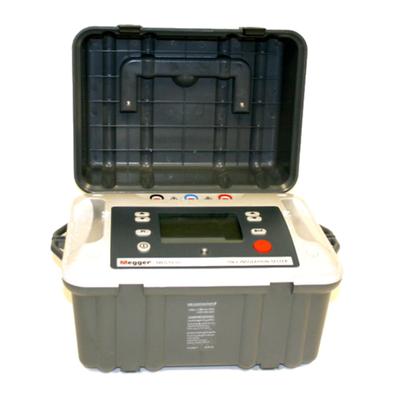
INSTRUMENT CONTROLS AND INDICATORS Measurement Terminals -ve, Guard, +ve RS232 port (under cover) Line Input Test Duration (under cover) increase/ decrease Display Test Voltage Scroll increase/ decrease Test Polarisation Index/ Start/Stop Power Insulation Resistance Red - HT On On/Off Green - Charging Battery... - Page 7 Polarisation Index/ Recording Insulation Resistance Timer ON Time Indicator Voltage Indicator Analogue Display Voltage at Voltage at Terminals Terminals Digital Display...
-
Page 8: On / Off Button
On / Off Button. The ‘Voltage Adjust’ buttons are used to increase or decrease the test Pressing the On / Off button powers up the MEG10-01 and initiates a voltage before starting a test or during a test if so desired. There are self-check and calibration routine. -
Page 9: Test Button
Test Terminals Pressing the ‘Test’ button for more than one second will start a test The MEG10-01 has three test terminal marked ‘+’, ‘-‘, and ‘G’. These using the preselected parameters and will start the ‘Time Indicator’ if terminals are designed to accept safety leads and have shutters across its use has been activated. -
Page 10: Rs232 Socket
The data format is 9600 baud, 8 bits, 1 Downloading Results stop bit, No parity. Connect your MEG10-01 to the RS232 port of a PC running Download Recording to on board memor y Manager, using the null modem cable supplied. Start Download To switch the instrument into Recording mode, press and hold the Manager on your PC, select MEG10-01 driver and right click the icon. -
Page 11: Battery Condition Indicator
circuit. The led will flash until this voltage is removed or discharged. automatic stop feature will be disabled and the test will continue until the ‘Test’ button is pressed to end the test. The elapsed test time will When the battery is being charged this l.e.d. will shine green. be displayed up to 99:59 after which the time display remains at 99:59. -
Page 12: Specifications
SPECIFICATIONS Timer 0 to 99:59 minutes. Instrument can be set Test Voltages (d.c.) 500 V, 1000 V, 2500 V, 5000 V, 10000 V to stop a test after a time limit or to run a Test Voltage Accuracy ±5% on 100 MΩ loads and above test indefinitiely. -
Page 13: Repair And Warranty
A number of independent instrument repair companies have been been impaired it should not be used, but sent for repair by suitably authorised for repair work on most Megger instruments, using genuine trained and qualified personnel. Megger spare parts. Consult the Appointed Distributor/Agent regarding spare parts, repair facilities, and advice on the best course of action to The protection is likely to be impaired if for example;... - Page 14 146 countries worldwide. F +1 214 337 3038 This instrument is manufactured in the United Kingdom. The company reserves the right to change the specification or design without prior notice. Megger is a re g i s t e red trademark www.megger.com...
Need help?
Do you have a question about the MEG10-01 and is the answer not in the manual?
Questions and answers