Table of Contents
Advertisement
Quick Links
Advertisement
Table of Contents

Subscribe to Our Youtube Channel
Related Manuals for Megger MFT70-US


Summary of Contents for Megger MFT70-US
- Page 1 MFT70-US Multifunction Tester With On - board memory User Manual...
-
Page 2: Table Of Contents
Making a voltage measurement ........................14 OR if using the mains plug lead SAI10:......................14 Frequency measurement ..........................15 Phase rotation ..............................15 Leakage current measurement ........................15 Temperature measurement ..........................15 Switch probe ..............................15 Continuity / resistance measurement ......................16 Nulling test lead resistance (up to 9.99 ohms) ..................16 www.megger.com... - Page 3 Battery .................................27 Battery charger ............................27 Fuse warning ...............................27 Invalid rotary switch setting .........................27 Continuity test .............................27 Insulation test ..............................27 GFCI Test ..............................27 GFCI range selection errors ..........................27 Test will not start ............................28 Sending, Storing, Deleting and Recalling Test Results..................29 www.megger.com...
- Page 4 Principle of operation (three-terminal resistance measurement) ..............35 Principle of operation (three-terminal resistance measurement using ART) ............35 Principle of operation (two-clamp stake-less resistance measurement) ............36 General Specification .............................37 Repair and Warranty ............................39 CALIBRATION, REPAIR AND SPARE PARTS .....................39 Deceleration of Conformity ..........................www.megger.com...
-
Page 5: Safety Warnings
• Failure to fit the correctly rated fuse will result in damage to the instrument in the event of an overload. • Special precautions are necessary when operating in situations where “live” Grounds may be encountered: isolation switches and fuses (not supplied with this instrument) must be used. www.megger.com... -
Page 6: Live Ground Safety Precautions
This instrument is internally protected against electrical damage when used for the purposes of testing low voltage electrical installations as defined herein. If used in a manor other than those defined in this user guide, the protection capabilities could be impaired with potential risk to the operator and the instrument. www.megger.com... -
Page 7: Symbols Used On The Instrument Are
Maximum nominal system voltage of 600 V Instrument protected by 2 x F2 1000 V 30 kA fuses Equipment complies with current EU Directives This equipment should be recycled as electronic waste Equipment complies with ‘C tick’ requirements 12 V DC charger socket www.megger.com... -
Page 8: Introduction
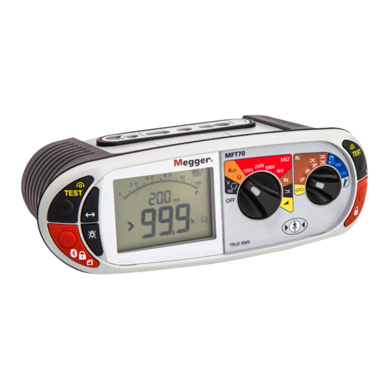
Introduction Introduction Congratulations on your purchase of a genuine Megger Multifunction tester. The MFT70 series Multi-function tester is a compact instrument designed to perform all of the functions required by the electrical contractor to fully test domestic, commercial and industrial wiring. Specially designed to comply with modern US International wiring regulations and standards, the MFT70 may be used on all single and three phase systems with rated voltages up to 300 V AC rms to ground. -
Page 9: Display Symbols
Ground noise voltage exceeds range for Type S GFCI (Type AC) accurate measurement of resistance Type S GFCI (Type A) Megger Voltage Clamp error Type B GFCI selected Megger Current Clamp error Fast or Full RAMP test selected Bluetooth enabled ®... -
Page 10: Waste Electrical And Electronic Equipment
Waste electrical and electronic equipment WEEE The crossed out wheeled bin placed on Megger products is a reminder not to dispose of the product at the end of its life with general waste. Follow local regulations. Megger is registered in the UK as a producer of electrical and electronic equipment. The registration number... -
Page 11: To Charge The Batteries
Spent Alkaline and NiMH batteries are classified as portable batteries and should be disposed of in accordance with local regulations. Megger is registered in the UK as a producer of batteries. The registration number is BPRN00142 www.megger.com... -
Page 12: Operation
RED button also performs bluetooth, storage and lock functions. Test button lock To lock the test button, hold down either of the RED test lock buttons with the symbol, whilst holding down the test button. If is displayed, the right hand buttons perform a scrolling function. www.megger.com... -
Page 13: Mode Button Functions
Current stake not within range (Rc). Other conditions that will inhibit testing include: Battery exhausted All testing will be inhibited in the event of a flat battery, refer to “Battery and fuse location, fitting and replacement” on page 10. www.megger.com... -
Page 14: Voltage, Frequency, Current And Temperature Measurement
Pressing either TEST button scrolls through L-E, N-E and L-N individual voltages. When the frequency of supply is shown, the voltage displayed reverts to the maximum voltage across all 3 terminals. Use the Mode button to select mV mode. www.megger.com... -
Page 15: Frequency Measurement
Leakage current measurement uses the optional accessory current clamp (Megger Current Clamp). 1. On the MFT70, set the primary range knob to clamp position 2. Connect to Megger Current Clamp (part number MCC1010) to the Megger Current Clamp socket on the MFT. -
Page 16: Continuity / Resistance Measurement
The null symbol will be displayed to indicate lead null is active. Lead null OFF TEST This null value is stored until the button is pressed again. TEST To cancel the LEAD NULL, separate the test leads and press the button. www.megger.com... -
Page 17: Making A Continuity Measurement
To store this result or to send it to a compatible device, refer to “Sending, Storing, Deleting and Recalling Test Results” on page 29. Continuity Buzzer ON/OFF Whilst in the continuity range, press the MODE button . This will toggle the buzzer ON and OFF. Buzzer ON = Buzzer OFF = No symbol www.megger.com... -
Page 18: Switch Probe (Sp5)
„ Use of fused leads. Insulation resistance NOTE: The insulation test is protected by a live circuit warning. Detection of a voltage over 50 V will inhibit testing. This applies whether or not the insulation test is locked on. www.megger.com... -
Page 19: Making An Insulation Measurement
• Auto discharge - Auto discharge facility automatically and safely discharges the circuit at the completion of an insulation test. • Live circuit warning - operates when connected to live circuits > 25 V. Testing is still permitted. • Test inhibited - Live circuits > 50 V will inhibit testing. www.megger.com... -
Page 20: Measurement Methods And Sources Of Error
3. Connect the instrument Phase (L1) and Ground (L2) terminals to the GFCI phase and ground terminals (or to the phase and ground of the circuit the GFCI is protecting). Use either the separate leads or mains plug leads. www.megger.com... -
Page 21: Touch Voltage Display
GFCI Testing - Possible sources of error Measurement results can be affected by the following: „ Significant operating errors can occur if loads, particularly rotating machinery and capacitive loads, are left connected during tests. „ A poor connection to the circuit under test. www.megger.com... -
Page 22: Useful Information
GFCIs that may stick or fail if not checked periodically. Ground resistance measurement The Megger MFT70 offers a unique solution to the measurement of ground or ground electrode (rod) supporting 2 and 3 wire measurements: This model can use an optional current clamp (Megger Current Clamp) to measure electrode (rod) resistance without disconnection, leaving the installation grounding system intact (Attached Rod Technique, ART). -
Page 23: Making A Measurement - Three Terminal Resistance Measurement
3. Set the right hand rotary selector switch to the position. TEST 4. Press and release the button. The instrument will perform pre-measurement check, the status of which will be indicated on the display. The three-terminal resistance reading will be displayed. www.megger.com... -
Page 24: Making A Measurement - Three Terminal Resistance Measurement Using Art
Caution: Ensure that the Megger Current Clamp jaw mating surfaces are free of dust and contamination. They must contact completely when the Megger Current Clamp is closed. Note: Currents carried by conductors in close proximity to the Megger Current Clamp may affect calibration and reduce the accuracy of measurements made. -
Page 25: Two-Clamp Stake-Less Measurement
2. Connect the instrument as shown above. 3. Close the Megger Current Clamp around the conductor under test. Ensure the arrow on the side of the jaw is pointing in the same direction as the arrow on the Megger Voltage Clamp. -
Page 26: Setup Options
To exit SETUP, turn the right range knob away from All settings can be restored to the factory defaults by setting RST to YES. Saving this setting will reset all options to default. The RST will then set back to NO. www.megger.com... -
Page 27: Warning Messages
“ERR - - -“ + Type S breaker symbol -Instrument has been set for Type S test, but Type S test is not valid with this setting. “ERR HI mA” -On VAR range, current is set too high for the selected test. www.megger.com... -
Page 28: Test Will Not Start
-Supply frequency is too low for loop test or GFCI test “FRE >65” -Supply frequency is too high for loop test or GFCI test “NO REF” -Loop R1 and R2 test attempted without having previously done a Zref test. www.megger.com... -
Page 29: Sending, Storing, Deleting And Recalling Test Results
Test results can be stored in the MFT, or downloaded immediately to a Bluetooth compatible device running ® Megger Download Manager. Refer to “Setup options” on page 26 Test results are stored in “Folders” against a set of circuit references as below: Folders: 000 to 255 Job number –... -
Page 30: Gfci
3. Press and hold the Bluetooth ® (Lock) button until ‘NO’ is displayed. 4. Use the Right Lock / Right Test buttons to display ‘YES’. 5. Press and hold the Bluetooth (Lock) button until ‘dEL Ok’ is displayed. ® www.megger.com... -
Page 31: Recalling Test Results To The Display
E.g. for Insulation, the test voltage is available for viewing. Sending stored test results via Bluetooth ® 1. Run Megger Download Manager 2. Using the approprate driver, follow the on-screen instructions. Sending individual (Blobbing) test results In order to Blob test data, the Store Mode needs to be set to Bluetooth ®... -
Page 32: Continuity Testing
PC or mobile device. The MFT test result will flash whilst the result is transmitted. 3. The test results will now appear in the correct box in the certificate open on your PC or mobile device. www.megger.com... -
Page 33: Bluetooth ® Pairing
7. Once you have clicked ‘Finish’ on the wizard on the PC/Laptop the pairing process will now be complete and your PC/Lap-top pairing code will be displayed on the MFT. You can now turn the dial and leave the settings position on the MFT. www.megger.com... -
Page 34: General Information
Cleaning and maintenance The MFT70 should only be opened or repaired by an approved Megger service or by Megger Instruments Limited. To clean the instrument, use a damp cloth or isopropyl alcohol if available. To clean the display window only use a lint free cloth. -
Page 35: Ground Resistance Testing - Basic Principles
By using a current transducer (the Megger Megger Current Clamp) to measure the current flowing through the electrode under test as a fraction of the total test current injected, the instrument can determine the individual resistance. -
Page 36: Principle Of Operation (Two-Clamp Stake-Less Resistance Measurement)
Megger Current Clamp can be used to obtain a measurement for the electrode under test. A defined test voltage is injected into the system using the Megger Voltage Clamp, inducing a current, I, to flow and be measured by the Megger Current Clamp. The model shown below can be simplified to the resistance of the electrode under test, Rx and the resistance of the other electrodes in parallel, i.e. -
Page 37: General Specification
0.01 Ω EN61557 range: 1.0 Ω to 1.99 kΩ Current: 0.45 mA or 4.5 mA. Noise rejection: 20 V pk/pk (7 V rms) Max probe resistances: Rp, Rc = 100 kΩ @ 50 V Max service error: ±20% ±3 digits www.megger.com... - Page 38 Installation Category: 600 V CAT III / 300 V CAT IV. (Max Phase to Phase 550 V) In addition switch probe and test leads are designed to meet IEC 1010-031:2008, Double insulated to Installation Category III, 300 V phase to Ground, 500 V phase to phase. www.megger.com...
-
Page 39: Repair And Warranty
RA number. 5. You may track the progress of your return on line at www.megger.com Approved Service Centres A list of Approved Service Centres may be obtained from the UK address above, or from Megger’s website at www.megger.com Deceleration of Conformity Hereby, Megger Instruments Limited declares that radio equipment manufactured by Megger Instruments Limited described in this user guide is in compliance with Directive 2014/53/EU. - Page 40 OTHER TECHNICAL SALES OFFICES Toronto CANADA, Sydney AUSTRALIA, Madrid SPAIN, Mumbai INDIA, and the Kingdom of BAHRAIN. Megger products are distributed in 146 countries worldwide. This instrument is manufactured in the United Kingdom. The company reserves the right to change the specification or design without prior notice.
Need help?
Do you have a question about the MFT70-US and is the answer not in the manual?
Questions and answers