Table of Contents
Advertisement
Quick Links
Advertisement
Table of Contents

Subscribe to Our Youtube Channel
Related Manuals for Ruijie XS-S1960-48GT4SFP-H Series


Summary of Contents for Ruijie XS-S1960-48GT4SFP-H Series
- Page 1 XS-S1960-48GT4SFP-H Series Switch Hardware Installation and Reference Guide V1.02...
- Page 2 This document is provided “as is”. The contents of this document are subject to change without any notice. Please obtain the latest information through the Ruijie Networks website. Ruijie Networks endeavors to ensure content accuracy and will not shoulder any responsibility for losses and damages caused due to content omissions, inaccuracies or errors.
- Page 3 It is intended for the users who have some experience in installing and maintaining network hardware. At the same time, it is assumed that the users are already familiar with the related terms and concepts. Obtaining Technical Assistance Ruijie Networks Website: https://www.ruijienetworks.com/ Technical Support Website: https://ruijienetworks.com/support...
-
Page 4: Product Overview
Hardware Installation and Reference GuideProduct Overview 1 Product Overview XS-S1960-48GT4SFP-H Series switch is a next-generation security and intelligent switch that features high performance, high security, multiple services and ease of use to meet the needs of the current networks. The XS-S1960-48GT4SFP-Hswitch can provide the complete end-to-end Quality of Service (QoS), flexible and abundant security policies and policy-based network management for various networks. - Page 5 Hardware Installation and Reference GuideProduct Overview Ratedvoltage range: 192V to 290V Rated current range: 0.5Ato 0.78A Earth Leakage ≤3.5mA Current Supported Not supported Power ≤ 40W Consumption Working 0º C to 50º C (32º F to 122º F) Temperature Storage -40º...
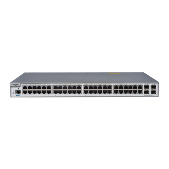
- Page 6 Hardware Installation and Reference GuideProduct Overview Front Panel Figure 1-5Front Panel of the XS-S1960-48GT4SFP-H Note: 1. Reset button 5. SFP ports 2. System status indicator 6. SFP ports 3. Console port 7. 10/100/1000BASE-T adaptive Ethernet port indicators 4.10/100/1000BASE-T adaptive Ethernet 8.
- Page 7 Hardware Installation and Reference GuideProduct Overview Power Supply The XS-S1960-48GT4SFP-H can be powered either with AC power or HVDC power. AC input: Rated voltage range: 100V to 240V, 50Hz/60Hz Maximum voltage range: 90V to 264V, 47Hz to 63Hz Frequency: 50Hz/60Hz Rated current: 1.5A Power cord: 10A power cord ...
- Page 8 Hardware Installation and Reference GuideProduct Overview Indicator Faceplate Status Indication Marker Solid green The system is in normal operation. 1. Over-temperature alarm. Serious Solid red over-temperature causes system restart. 2. The system is faulty. The port is NOT connected. Solid green The port is connected at 1000Mbps.
-
Page 9: Preparation Before Installation
2 Preparation before Installation 2.1 Safety Suggestions To avoid personal injury and equipment damage, please carefully read the safety suggestions before you install the XS-S1960-48GT4SFP-H series. The following safety suggestions do not cover all possible dangers. 2.1.1 Safety Precautions for Installing the System ... -
Page 10: Static Discharge Damage Prevention
Hardware Installation and Reference Guide Preparation before Installation theoretical maximum leakage current of all the power supplies in the system. For example, if a system is equipped with eight identical power supplies, the leakage current of each power supply is equal to or less than 3 mA, and the leakage current of the system totals 24 mA. -
Page 11: Installation Site Requirements
Hardware Installation and Reference Guide Preparation before Installation 2.2 Installation Site Requirements To ensure the normal working and a prolonged durable life of the equipment, the installation site must meet the following requirements. 2.2.1 Ventilation Requirements For the XS-S1960-48GT4SFP-Hseries, you must ensure that sufficient space(10cm distance from both sides and the back panel of the cabinet) is reserved at the ventilation openings to ensure the normal ventilation. - Page 12 Hardware Installation and Reference Guide Preparation before Installation Substance Concentration Limit (particles/m3) Dust particles (diameter ≥0.5μm) ≤3.5×10 Dust particles (diameter ≥5μm) ≤3×10 Apart from dust, the salt, acid and sulfide in the air in the equipment room must also meet strict requirements; as such poisonous substances may accelerate the corrosion of the metal and the aging of some parts.
- Page 13 Hardware Installation and Reference Guide Preparation before Installation Safety Grounding The equipment using AC power supply must be grounded by using the yellow/green safety grounding cable. Otherwise, when the insulating resistance decreases the power supply and the enclosure in the equipment, electric shock may occur. Ensure that a protective earth wire is provided in the building.
- Page 14 Hardware Installation and Reference Guide Preparation before Installation prevent the current of high-voltage lightning from passing the switch directly through the mains supply cable to a certain extent. The lightning line banks are not provided and should be purchased by users as required. For the usage of lightning line banks, refer to their related manuals.
-
Page 15: Product Installation
Whether the requirements of temperature and humidity are met for the switch Whether power cables are already laid out and whether the requirements of electrical current are met Whether related network adaption lines are already laid out 3.3 Installing the XS-S1960-48GT4SFP-H Series Precautions... - Page 16 Hardware Installation and Reference GuideProduct Installation During installation, note the following points: Connect the power cables of different colors to the corresponding grounding posts. Ensure that the interface of the power supply cable is well connected to the power interface of the device. The power power cable retention clips cables must be protected using after they are connected to the device.
- Page 17 Hardware Installation and Reference GuideProduct Installation Figure 3-4Fixing the Brackets to the Rack 3.3.2 Mounting the Switch onthe Wall The XS-S1960-48GT4SFP-Hseries switches can be mounted on a wall. Step 1: Take out supplied screws and brackets. And then rotate the brackets by 90° when it is mounted on the wall. Figure 3-5Attaching the Mounting Brackets to the Switch for Wall-Mounting...
- Page 18 Hardware Installation and Reference GuideProduct Installation Step 2: Fix the switch onto the wall by using expansion screws. Figure 3-6 Fixing the Switch to the Wall The XS-S1960-48GT4SFP-H switches suitable for mounting on concrete or other non-combustiblesurface only. 3.3.3 Mounting the Switch to a Workbench In some cases, users do not have the 19-inch standard cabinet.
-
Page 19: Checking After Installation
Hardware Installation and Reference GuideProduct Installation Step 2: Place the switch on the workbench and ensure good ventilation condition around the switch. Figure 3-8 Placing the Switch on the Workbench 3.4 Checking after Installation Before checking the installation, switch off the power supply so as to avoid any personal injury or damage to the component due to connection errors. -
Page 20: System Debugging
Hardware Installation and Reference GuideSystem Debugging 4 System Debugging 4.1 Establishing the DebuggingEnvironment Establishing the DebuggingEnvironment Connect the PC to the console port of the switch through the console cable, as shown in Figure 4-1. Figure 4-1Schematic Diagram of the Configuration Environment Connecting the Console Cable ... - Page 21 Hardware Installation and Reference GuideSystem Debugging Enter the name of the new connection and click OK, the interface as shown in Figure 4-3 is displayed. Choose the serial port used currently in the column [use when connecting]. Figure 4-3 After choosing the serial port, click OK to display the serial port parameter setting interface, set the baud rate to 9600, data bit to 8, parity check to none, stop bit to 1 and flow control to none.
- Page 22 Hardware Installation and Reference GuideSystem Debugging After setting the parameters, click OK to enter the hyper terminal interface. 4.2 Startup Check 4.2.1 Checking before the Device is Powered on The switch is fully grounded. The power cable is correctly connected. ...
-
Page 23: Maintenance And Troubleshooting
5.2 Troubleshooting Common Faults Symptom Possible Causes Solution Forgetting the A password is manually configured but Please contact Ruijie Networks Customer Service management interface it is forgotten. Department for technical support. login password The status indicator is The power supply module does not... - Page 24 Hardware Installation and Reference GuideMaintenance and Troubleshooting Symptom Possible Causes Solution Check whether the power cord is connected. Remove the non-working or faulty power supply. The serial port The serial port connected to the switch Change the serial port opened by the configuration console has no output does not match that opened by the software to be the one connected to the switch.
-
Page 25: Appendix A: Connectors And Connection Media
Hardware Installation and Reference GuideAppendix A: Connectors and Connection Media 6 Appendix A: Connectors and Connection Media 1000BASE-T/100BASE-TX/10BASE-T Ports The 1000BASE-T/100BASE-TX/10BASE-T is a port that supports adaptation of three rates, and automatic MDI/MDIX Crossover at these three rates. The 1000BASE-T complies with IEEE 802.3ab, and uses the cable of 100-ohm Category-5 or Supper Category-5 UTP or STP, which can be up to 100 m. - Page 26 Hardware Installation and Reference GuideAppendix A: Connectors and Connection Media Optical Fiber Connection For the optical fiber ports, select single-mode or multiple-mode optical fibers for connection according to the fiber module connected. The connection schematic diagram is shown in Figure A-4: Figure A-4Optical Fiber Connections...
-
Page 27: Appendix B Mini-Gbic Modules
Hardware Installation and Reference GuideAppendix B Mini-GBIC Modules 7 Appendix B Mini-GBIC Modules We provide appropriate SFP modules (Mini-GBIC) modules according to the types of interfaces of the switch modules. You can select the module to suit your specific needs. The 100M/1000M SFP module supports the following modules as well as the 100M/1000M fiber/copper conversion SFP module (Mini-GBIC-GT). - Page 28 Hardware Installation and Reference GuideAppendix B Mini-GBIC Modules MINI-GBIC-ZX100-SM1 Single-mode 1,550 9/125 100km fiber For the optical module with transmission distance exceeding 40km and more, one on-line optical attenuator should be added on the link to avoid the overload of the optical receiver when short single-mode optical fibers are used. Table B-3Pairing of BIDI SFP Modules Rate/Distance Pairing Modules...
-
Page 29: Appendixc Lightning Protection
Hardware Installation and Reference GuideAppendixC Lightning Protection 8 AppendixC Lightning Protection Installing AC Power Arrester (lightning protection cable row) The external lightning protection cable row should be used on the AC power port to prevent the switch from being struck by lightning when the AC power cable is introduced from the outdoor and directly connected to the power port of the switch. - Page 30 Hardware Installation and Reference GuideAppendixC Lightning Protection Installing the Ethernet Port Arrester During the switch usage, the Ethernet port arrester should be connected to the switch to prevent the switch damage by lightning before the outdoor network cable connects to the switch. Tools: Cross or straight screwdriver, Multimeter,Diagonal pliers Installation Steps: Tear one side of the protection paper for the double-sided adhesive tape and paste the tape to the framework of the...
- Page 31 Hardware Installation and Reference GuideAppendixC Lightning Protection You should pay attention to the following conditions during the actual installation to avoid influencing the performance of the Ethernet port arrester: Reversed direction of the arrester installation. You shall connect the external network cable to the “IN” end and connect the switch Ethernet port to the “OUT”...
- Page 32 Hardware Installation and Reference GuideAppendix D Cabling Recommendations in Installation 9 Appendix D Cabling Recommendations in Installation When the switches are installed in standard 19-inch cabinets, the cables are tied in the binding rack on the cabinet by the cable management bracket, and top cabling or bottom cabling is adopted according to the actual situation in the equipment room.
- Page 33 Hardware Installation and Reference GuideAppendix D Cabling Recommendations in Installation Cables of different types (such as power cords, signal cables, and grounding cables) should be separated in cabling and bundling and no mixed bundling is allowed. When they are close, crossover cabling can be adopted. In the case of parallel cabling, power cords and signal cables should maintain a distancenot less than 30 mm.
- Page 34 Hardware Installation and Reference GuideAppendix D Cabling Recommendations in Installation Figure D-3 Bundling up cables (3) Cables not to be assembled or remaining parts of cables should be folded and placed in a proper position of the cabinet or cabling slot. The proper position indicates a position that will not affect device running or cause device damage or cable damage during commissioning.
- Page 35 Hardware Installation and Reference GuideAppendix D Cabling Recommendations in Installation Figure D-4 Cable fastening The hard power cable should be fastened at the terminal connection area to prevent stress on terminal connection and cable. Do not use self-tapping screws to fasten terminals. ...
- Page 36 Hardware Installation and Reference GuideAppendix D Cabling Recommendations in Installation For wiring terminal blocks (such as air switches) of the cold pressing terminal type, the metal part of the cold pressing terminal should not be exposed outside the terminal block when assembled.
-
Page 37: Appendix Esite Selection
Hardware Installation and Reference GuideAppendix ESite Selection 10 Appendix ESite Selection The machine room should be at least 5km away from the heavy pollution source such as the smelter, coal mine and thermal power plant, 3.7km away from the medium pollution source such as the chemical industry, rubber industry and electroplatingindustry, and 2km away from the light pollution source such as the food manufacturer and leather plant.
Need help?
Do you have a question about the XS-S1960-48GT4SFP-H Series and is the answer not in the manual?
Questions and answers