
Related Manuals for Ruijie RG-S7800 Series


Summary of Contents for Ruijie RG-S7800 Series
- Page 1 Hardware Installation Guide RG- S7800 Series High-density Multi-service IPv6 Core Routing Switch...
-
Page 3: Copyright Statement
Ruijie Networks reserves all copyrights of this document. Any reproduction, excerption, backup, modification, transmission, translation or commercial use of this document or any portion of this document, in any form or by any means, without the prior written consent of Ruijie Networks is prohibited. - Page 5 Documentation CD-ROM: The documentation of Ruijie Networks switches is stored in the CD-ROM package, which is provided to you together with the product you purchase. The CD-ROM is updated frequently, and may be more current than the printed documents.
-
Page 6: Obtaining Technical Assistance
Chapter 1 Product Overview S7800 SeriesHardware Installation Guide Obtaining Technical Assistance Ruijie Networks provides excellent technical support services for all our products. You can obtain the technical assistance you need through any of the following channels: Website of Ruijie Networks from which you can obtain the latest product documentation, causes and problems analysis of product faults, application solutions, and software upgrade. -
Page 7: Product Overview
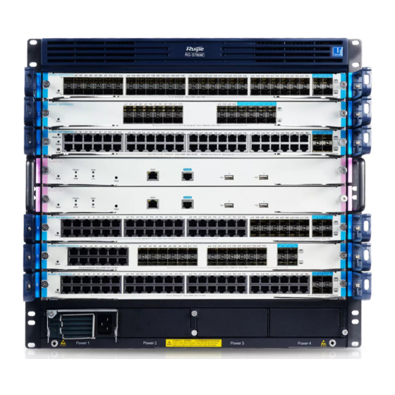
Figure 1-1 Typical Application for RG-S7800 swiches RG-S7800 series support the dual CMs and the power supply redundancy, providing two kinds of the switch with 6 horizontal slots and 4 horizontal slots respectively:... -
Page 8: Technical Specifications
Chapter 1 Product Overview S7800 SeriesHardware Installation Guide Technical Specifications Table 1-1 RG-S7800 Product Technical specifications Product Model RG-S7806-ISeries RG-S7804-ISeries Slot 6 (two slots for CMs) 4 (one slot for CM) Mudule Type M7800-CM M7800-CM M7800-02XS24SFP/8GT M7800-02XS24SFP/8GT M7800-24SFP/8GT M7800-24SFP/8GT M7800-48GT M7800-48GT M7800P-48GT M7800P-48GT... - Page 9 S7800 Series Hardware Installation Guide Chapter 1 Product Overview RG-S7806-ISeries Switch System 1.3.1 RG-S7806-ISeries Switch RG-S7806-ISeries uses a standards-based 19-inch chassis with 308.5mm high, 436mm wide, and 472mm deep and provides 2 slots for the CMs(control modules) and 4 slots for the service modules.
- Page 10 Chapter 1 Product Overview S7800 SeriesHardware Installation Guide Figure 1-3 RG-S7806-ISeries Module Installation ○ 1 Installation handler, used to help the device racking; ○ 2 M7806-FAN I installation location; ○ 3 M7800-CM module installation location; ○ 4 M7800 series service card installation location; ○...
- Page 11 S7800 Series Hardware Installation Guide Chapter 1 Product Overview 1. For RG-S7806-ISeries, the total set system power must be larger than the device working power; or the system error will occur. For RG-S7806-ISeries, the set PoE power must be larger than the Warning summary of all PoE service card power;...
- Page 12 Chapter 1 Product Overview S7800 SeriesHardware Installation Guide M7806-FAN I module provides the intelligent speed control function. Based on the temperature in the working environment and the pratical working temperature of each CM and service card module in the RG-S7806-ISeries system, M7806-FAN I will intelligently control the RPM of each fan, in order to reduce the power consumption and the noise.
- Page 13 S7800 Series Hardware Installation Guide Chapter 1 Product Overview Figure 1-6 RG-S7804-ISeries Module Installation ○ 1 Installation handler, used to help the device racking; ○ 2 M7804-FAN I installation location; ○ 3 M7800-CM module installation location; ○ 4 M7800 series service card installation location; ○...
- Page 14 Chapter 1 Product Overview S7800 SeriesHardware Installation Guide 1. For RG-S7804-ISeries, the total set system power must be larger than the device working power; or the system error will occur. For RG-S7804-ISeries, the set PoE power must be larger than the Warning summary of all PoE service card power;...
- Page 15 S7800 Series Hardware Installation Guide Chapter 1 Product Overview M7804-FAN I module provides the intelligent speed control function. Based on the temperature in the working environment and the pratical working temperature of each CM and service card module in the RG-S7804-ISeries system, M7804-FAN I will intelligently control the RPM of each fan, in order to reduce the power consumption and the noise.
-
Page 16: Power System
Chapter 1 Product Overview S7800 SeriesHardware Installation Guide Figure 1-9 RG-S7804-ISeries Ventilation/heat dissipation system 1.5.2 Power System The RG-S7800 power system includes the host power system and the PoE power system, wherein the host power system provides the power for the fan、CMs and the service card module, and the PoE power system provides the power for the service card with PoE enabled to implement the external PoE power supply. - Page 17 S7800 Series Hardware Installation Guide Chapter 1 Product Overview Sign Description Detailed Information OFF: The module has not been powered on or the input power fault. Input LED Green: The input power works normally. . OFF: The module has been powered off. Output LED Green: The output power works normally.
- Page 18 Output voltage 300W Built-in power Figure 1-11 shows the basic appearance of the RG-PA300P, the host system power modulel for the RG-S7800 series switch. Table 1-10 describes the LEDs for the RG-PA300P: Figure1-11 Appearance of the RG-PA300P ○ 1 Power LED;...
- Page 19 S7800 Series Hardware Installation Guide Chapter 1 Product Overview Sign Description Detailed Information OFF: The module has been powered off. Output LED Green: The output power works normally. OFF: The module works normally. FAIL Alarm LED Red: Module fault. OFF: The external PoE power module does not work. External power LED Green: The external PoE power module is working.
- Page 20 Chapter 1 Product Overview S7800 SeriesHardware Installation Guide Figure 1-13 Appearance of the RG-PSE Figure 1-14 Appearance of the RG-PSE-M Table 1-12 describes the RG-7800’s external PoE power system LEDs: Sign Description Detailed Information OFF: The module has not been powered on or the input power fault.
- Page 21 S7800 Series Hardware Installation Guide Chapter 1 Product Overview 1. PoE power module configuration shall be calculated according to the number of ports providing the external power. The maximum power formula is 15.4*N (N refers to the maximum number of the POE ports being used. N<48 for the single M7800P-48GT) 2.
- Page 22 Chapter 1 Product Overview S7800 SeriesHardware Installation Guide 1.5.3 Air-filter RG-S7800’s air filter locates on the left of the chassis. The air filter is used to prevent the dust and debris from being blown to the switch frame to cause the cicuit board damage. To this end, the air filter must be installed and cleaned periodically to ensure the good ventilation/heat dissipation and the normal working of the switch.
- Page 23 Chapter 2 Modules Modules Overview Under the premise of in strict compliance with the industrial standards, RG-S7800 series switches adopt the modular design and provide the sound, reasonable and independent modules by subdividing the system modules and unifying the module interfaces. RG-S7800 series switches provide 10M/100M/1000M adaptive Ethernet copper ports, 1000M SFP(single-mode/multi-mode) optic fiber interfaces and 10G optic fiber ports, ect.
-
Page 24: Led Description
Chapter 2 Modules S7800 SeriesHardware Installation Guide LED Description 2.2.2 Table 2-2 LEDs on the front panel Sign Description Detailed Information OFF: The module has not been powered on. Red: The module is faulty. Flashing green: The module is initializing; if it Status System LED keeps on flashing, the module is faulty. -
Page 25: Technical Specifications
10/100/1000BASE-T port. Only one port can be used at the same time. The M7800-24SFP/8GT module supports the 1000BASE-X and Note 100BASE-FX mode. For how to configure the ports in the required working mode, please refer to the Configuration Manual of Ruijie Networks. - Page 26 Flashing green: The data is transmitted on the port. RG-S7800 series switch provides the power management function. Upon being inserted into the chassis or powering on the chassis, all RG-S7800 service cards are not powered on and all LEDs are OFF untill the CMs’ control over powering on the service cards based on the current power condition.
- Page 27 S7800 Series Hardware Installation Guide Chapter 2 Modules Figure 2-3 Basic appearance of the M7800-02XS24SFP/8GT 2.4.1 Technical Specifications Table2-5 Technical specifications of M7800-02XS24SFP/8GT Product Model M7800-02XS24SFP/8GT Standard IEEE 802.3-2005 Compliance 2 10G SFP+ ports, 16 1000M SFP ports and 8 1000M fiber/copper Port type combo ports 10GBASE-SR(850nm) Multi-mode optic fiber...
- Page 28 The M7800-02XS24SFP/8GT module supports the 1000BASE-X and Note 100BASE-FX mode. For how to configure the ports in the required working mode, please refer to the Configuration Manual of Ruijie Networks. LED Description 2.4.2 The M7800-24SFP/8GT module provides various system LEDs, wherein the Status LED...
- Page 29 S7800 Series Hardware Installation Guide Chapter 2 Modules M7800-48GT Figure 2-4 shows the basic appearance of M7800-48GT, the line card of RG-S7800. M7800-48GT provides 48 1000M 10/100/1000M BASE-T ports. The M7800-48GT module is hot swappable. Figure 2-4 Basic appearance of the M7800-48GT Technical Specifications 2.5.1 Table2-7 Technical specifications of M7800-48GT...
- Page 30 Flashing green: The data is transmitted on the port. RG-S7800 series switch provides the power management function. Upon being inserted into the chassis or powering on the chassis, all RG-S7800 service cards are not powered on and all LEDs are OFF untill the CMs’ control over powering on the service cards based on the current power condition.
- Page 31 Dimensions 378*290×45.2 ( Lx W x Hmm) RG-S7800 series PoE function combines the internal and external power supply. The maximum power formula is 15.4*N (N refers to the maximum number of the POE ports being used.) The rated power for the RG-PA300P power module is 300W and the maximum rated power for the external PSE power module is 1600W(up to configure 2 RG-PA800-PSE modules).
- Page 32 Flashing yellow: Overload PoE power supply on the port. RG-S7800 series switch provides the power management function. Upon being inserted into the chassis or powering on the chassis, all RG-S7800 service cards are not powered on and all LEDs are OFF untill the CMs’ control over powering on the service cards based on the current power condition.
-
Page 33: Chapter 3 Preparation Before Installation
S7800 Series Hardware Installation Guide Chapter 3 Preparation before Installation Preparing for Installation Safety Suggestions To avoid bodily injury and equipment damage, please carefully read the safety suggestions before you install RG-S7800. The following safety suggestions do not cover all possible dangers. Warning 3.1.1 Safety Precautions for Installing... -
Page 34: Static Discharge Damage Prevention
Chapter 3 Preparation before Installation S7800 SeriesHardware Installation Guide Please carefully check for any potential danger in the working area, for example, ungrounded power supply, unreliable grounding of the power supply and damp/wet ground or floor. Find out the location of the emergency power supply switch in the room before installation. -
Page 35: Installation Site Requirements
S7800 Series Hardware Installation Guide Chapter 3 Preparation before Installation Laser Safety 3.1.5 Among the modules supported by RG-S7800, there are a great number of optical modules that are Class I laser products. Therefore, pay attention to the following during your use of this product: When a fiber transceiver works, ensure that the port has been connected with an fiber or is covered with a dust cap so as to keep out dust and avoid burning your eyes. -
Page 36: Cleanness Requirements
Chapter 3 Preparation before Installation S7800 SeriesHardware Installation Guide In an environment with high temperature, the equipment is subjected to even greater harm, as its performance may degrade significantly and its useful life may be shortened in the case of long-term exposure that expedites the aging process. Therefore, the ambient temperature and humidity of the RG-S7800 equipment must meet the requirements listed in Table 3-1: Table 3-1Temperature and humidity requirements of the RG-S7800... -
Page 37: System Grounding Requirements
S7800 Series Hardware Installation Guide Chapter 3 Preparation before Installation AC input voltage: 90VAC to 264VAC, 47Hz to 63Hz Power: >1000W. The RG-S7800 provides N+1 redundancy of power supply. You are recommended to use multiple power supplies for the equipment to ensure its continuous and stable operation by avoiding the impact of unexpected power Note failures on the equipment. -
Page 38: Precaution For Fiber Connection
Fiber optic cleaning Air-laid paper, fiber end microscope tools Meter Multimeter, Errormeter, Optic-power meter RG-S7800 series is not shipped with a tool kit. You need to prepare a tool kit by yourself. Note Unpacking Requirements 3.5.1 Goods Checklist 1. - Page 39 S7800 Series Hardware Installation Guide Chapter 3 Preparation before Installation Packing list 2. RG-S7800 accessory carton Power supply cords (only for AC power supply) Screws Documentation Packing list 3. Module carton Various modules Packing list Documentation A normal delivery should contain the above mentioned items, which may differ from the actual delivery, depending on purchase contracts.
-
Page 40: Switch Installation
S7800 Series Hardware Installation Guide Chapter 4 Switch Installation Switch Installation 1. Before you install the RG-S7800, make sure you have carefully read Chapter 3 and this chapter. 2. Be sure that the requirements set forth in Chapter 3 have been met. Note... -
Page 41: Installation Flow
Chapter 4 Switch Installation S7800 Series Hardware Installation Guide Installation Flow Assemble S7800 before installation Install the cabinet Mount S7800 into the cabinet Ground the system Connect the power supply Insert various modules Connect external port cables or fibers of various modules Bind cables or fibers Installation check... -
Page 42: Cabinet Installation
S7800 Series Hardware Installation Guide Chapter 4 Switch Installation The related network cables have already been deployed at the installation location. Rated power supply is selected. Cabinet Installation 4.3.1 Precautions When you install the cabinet, pay attention to the following: All expansion bolts for fastening the cabinet base to the ground should be installed and tightened in sequence from bottom up (large plain washer, spring washer, and nut), and the installation holes on the base and the expansion bolts should be well aligned. -
Page 43: Installing Power Supply
RG-S7800 system’s built-in PoE power module supports the AC power module RG-PA300P. The built-in PoE power slot is at the back of the RG-S7800 series switch(as shown in the figure1-3 and the figure1-6). Remove the blank panel of the power module by loosening the... - Page 44 RG-PSE-M’s RS485 interface. (6) Complete the installation of the external PoE power systerm for the RG-S7800 series switches. For the more detailed installation, please refer to the RG-PSE Power Quick Installation Guide.
-
Page 45: Simple Grounding Steps
Chapter 4 Switch Installation S7800 Series Hardware Installation Guide Simple Grounding Steps 4.6.2 Release the nut on the rear grounding post of the equipment. Lock the terminal of the grounding cable to the grounding pole. Tighten the nut. Connect the related terminals according to the above steps and the wiring diagram. Figure 4-1 Schematic Diagrams for the RG-S7800 Grounding To guarantee the security of the person and the device, the RG-S7800 must be well-grounded. - Page 46 S7800 Series Hardware Installation Guide Chapter 4 Switch Installation Connect the other end of the power cable to the corresponding socket or connector. Connecting the Cables of the Management Module 4.8.1 Simple Connection Steps Connect the end of the Ethernet cable with the RJ45 connector to the RJ-45 interface of the control module, and connect the DB9 connector to the NM or control terminal.
-
Page 47: Connecting The External Interface Cables
Chapter 4 Switch Installation S7800 Series Hardware Installation Guide 4.11 Connecting the External Interface Cables 4.11.1 Precautions Correctly distinguish single-mode and multi-mode fibers and ports. Avoid bends of small radius at the connector. Simple Connection Steps 4.11.2 Connect one end of the RJ45 connector for configuring Ethernet cables to the Ethernet interface of the device board and the other end to the NMS or a control terminal;... -
Page 48: Verifying The Power Supply
S7800 Series Hardware Installation Guide Chapter 4 Switch Installation After installing the equipment, verify if the front/back cabinet doors can be closed. Verify that the cabinet has been fastened completely, and does not move or tilt. Verify that the equipment has been installed in the cabinet, and all the cables have been fastened to the cabinet. -
Page 49: Chapter 5 Maintenance And Troubleshooting
CLI commands, including: Module/board in-position status Port configuration information and status Fan and power supply working status Temperature status For the monitoring commands, see RG-S7800 series Software Configuration Guide. RG-S7800 Hardware Maintenance Board Maintenance 5.2.1 To replace a board, do replacement according to the instructions provided in Section 4.9 and 4.10. -
Page 50: General Installation Troubleshooting Flow
Module Fuse Specification The table 5-1 lists the specifications for the module fuses. To replace the old fuse wire with the correspondent new one, please contact the technical support representatives of Ruijie Networks. Table 5-1 Specifications for the module fuses... -
Page 51: Common Troubleshooting Procedures
Check the connection of the serial port and its parameters Check the connection of the fibers or ports cables of various Contact Ruijie Technical Support for hardware problems Common Troubleshooting Procedures Fault 1: The system login password is lost. [Fault Description] The system login password of the switch is forgotten or lost, and so it is not possible to configure the data. - Page 52 Chapter 5 Maintenance and Troubleshooting S7800 SeriesHardware Installation Guide [Troubleshooting] Please contact Ruijie Customer Service Department for technical support. Fault 2: The AC power module does not work. [Fault Description] The Status LED of each linecard is OFF, the Power LED of the fan tray is OFF, and the fan does not work.
- Page 53 S7800 Software Configuration Guide. If not, modify the serial port configuration parameters. If there is still no serial port printed information, please contact Ruijie Customer Service Department for technical support.
- Page 54 If so, please add more power modules to provide the enough power for the power supply. If all checkings are OK, but the newly-inserted service card module still cannot be powered on, please contact Ruijie Customer Service Department for technical support.
- Page 55 S7800 Series Hardware Installation Guide Appendix AppendixA Connectors Connection Media 1000BASE-T/100BASE-TX/10BASE- T Port 1000BASE-T/100BASE-TX/10BASE-T is a port that supports adaptation of three rates, and automatic MDI/MDIX Crossover at these three rates. The 1000BASE-T complies with IEEE 802.3ab, and uses up to 100m of 100-ohm Category-5 or Supper Category-5 UTP or STP cable.
-
Page 56: Fiber Connection
Appendix S7800 Series Hardware Installation Guide Figure A-3 shows the connections of the straight-through and crossover twisted pairs of the 100BASE-TX/10BASE-T. Figure A-3 Connections of the twisted pairs of the 100BASE-TX/10BASE-T 2. Fiber Connection For the optic ports, select single-mode or multiple-mode fibers for connection according to the fiber module connected. - Page 57 S7800 Series Hardware Installation Guide Appendix AppendixB Mini-GBIC and 10G SFP+ Modules 1000M SFP module (Mini-GBIC module) and 10G SFP+ module are available to address the requirements of interface types of switch modules. You can select the SFP or SFP+ module to suit your specific needs.
- Page 58 Appendix S7800 Series Hardware Installation Guide fiber Single-m 9/125 SFP-100M-SM-4 1310 ode optic 40km fiber Single-m 9/125 SFP-100M-SM-8 1550 ode optic 80km fiber 2. Models and Technical Specifications of 10G SFP+ Module Table B-2 10G SFP+ modules and technical specification Optical Reception Mode...
- Page 59 S7800 Series Hardware Installation Guide Appendix AppendixC Switch Lightning Protection 1. Installing AC Power Arrester(lightning protection cable row) The external lightning protection cable row shall be used on the AC power port to prevent the switch from being struck by lightning when the AC power cable is introduced from the outdoor and directly connected to the power port of the switch.
-
Page 60: Installation Steps
Appendix S7800 Series Hardware Installation Guide 1. The power arrester is not provided, the user shall purchase it to address the pratical requirement; Warning 2. Make sure that the PE terminal of the power arrester has been well-grounded; 3. After connecting the switch AC power plug to the socket of the power arrester(lightning protection cable row), lightning protection function implements if the RUN LED is Green and the ALARM LED is OFF. -
Page 61: Installation Tips
S7800 Series Hardware Installation Guide Appendix connected to the end of IN, while the adapter cable is connected to the end of OUT) and observe whether the LED on the borad is normal or not. Step 5: Use the nylon button to bundle the power cables. Figure C-2 Schematic Diagram for the Ethernet port Arrester Installation 1. - Page 62 Appendix S7800 Series Hardware Installation Guide on the switch, it needs to install the arresters on all connection ports for the purpose of the lightning protection.
Need help?
Do you have a question about the RG-S7800 Series and is the answer not in the manual?
Questions and answers