Table of Contents
Advertisement
Advertisement
Table of Contents

Related Manuals for Navman Qube 300


Summary of Contents for Navman Qube 300
- Page 1 Qube 300 Installation Manual...
-
Page 2: Disclaimer
Qube 300 | Installation Manual Disclaimer It is the Owner’s sole responsibility to install and use the Qube 300 (the Product) in a manner that will not cause accidents, personal injury or property damage. For the purpose of this notice, “Owner”, “you” and “your”... -
Page 3: Table Of Contents
2.2 Other Components Required ......................5 Mounting Locations ......................... 6 Antenna Mounting Location ....................... 6 3.2 Qube 300 Mounting Location ......................6 Installation & Wiring ....................... 8 Before Starting ......................... 8 4.2 3-Wire Basic Tracking & Antenna Connections ................8 4.3 Connect Any Auxiliary Devices ....................... -
Page 4: Introduction
Introduction Overview The Navman Wireless Qube 300 is an Automatic Vehicle Location unit (AVL) that is installed into fleet vehicles. It communicates with a server and allows vehicle information to be stored and monitored. It is a combined GPS (Global Positioning System) and communications product that contains: ... -
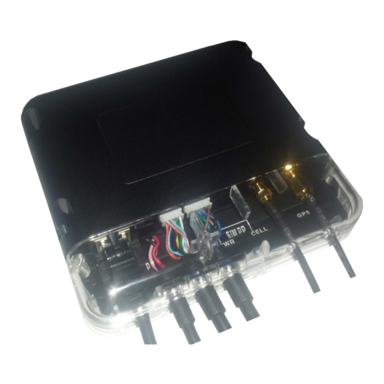
Page 5: Qube 300 Hardware
Note: You can use a combi-antenna OR a separate GPS Antenna and a separate Cellular Antenna. Contact your Navman Wireless dealer for advice on the best choices for your type of installation and for ordering information, if necessary. Depending on the installation requirements, you may also need the following components: ... -
Page 6: Mounting Locations
Note: The combination antenna (SAP#10001358) is not waterproof – do not mount outside of the vehicle. Use of an antenna that is not approved by Navman Wireless, or antenna installation that is contrary to the recommendations provided by the antenna manufacturer or Navman Wireless may result in poor GPS or cellular performance, and may invalidate the product warranty. - Page 7 Qube 300 | Installation Manual The installation location must: be a rigid surface or a large wiring loom, where the Qube 300 can be firmly secured be dry allow MDT/M-Nav or other peripheral device connections allow the diagnostic LEDs on the Qube 300 to be seen ...
-
Page 8: Installation & Wiring
Installation & Wiring Before Starting Check that all cables are long enough to reach between the chosen Qube 300 location, the antenna location, and the ignition loom (or fuse box). Test the proposed antenna location to check whether it will give the best performance. -
Page 9: Connect Any Auxiliary Devices
4.3 Connect Any Auxiliary Devices The Qube 300 has 3 serial ports. Use these to connect to other Navman Wireless devices, such as an M-Nav or MDT, or to third-party equipment for serial data communication. The Qube 300 also has several digital... - Page 10 Qube 300 | Installation Manual White +3.8V DC Reference for Analogue Input Yellow Multi I/O-1 Digital Input OR Digital Output OR Analogue Input 1 (Also Wake from Sleep) Green Multi I/O-2 Digital Input OR Digital Output OR Analogue Input 2...
-
Page 11: Connect Any Optional Sensors
Qube 300 | Installation Manual 4.4 Connect Any Optional Sensors 4.4.1 Digital Inputs DI-1 to DI-4 The Digital Inputs can be configured to detect high voltages (Active High) OR low voltages (Active Low). Active High Input Configuration When configured as an Active High Input, the input state is considered ON when it becomes high. The... - Page 12 Analogue Input. 4.4.4 Navman Wireless Temperature Probes The Qube 300 can support up to six Navman Wireless digital temperature probes and can also use some of Qube 300 & Navman Wireless the Multi I/O and Digital Inputs for temperature event monitoring. See the Temperature Probes Installation Manual for installation instructions.
-
Page 13: Install The Security Cover
I / O cable . Angle the upper part of the security cover onto the front of the Qube 300 then push it down into place. The upper and lower parts of the security cover should fit snugly together with no gap between them. The two screw holes at the sides of the Qube 300 should align with the two screw pillars at the sides of the security cover. -
Page 14: Testing And Fault Finding
3. Watch the meter and start the vehicle, to ensure that the voltage remains ON during start-up. If any of these tests fail, the Qube 300 is not connected to the correct supply. Please find the correct wire. 5.2 Check Data and GPS Reception 1. -
Page 15: Dimensions
Qube 300 | Installation Manual Dimensions... -
Page 16: Specifications
Qube 300 | Installation Manual Specifications Absolute Maximum Voltage: 40 V DC • Digital Output Physical Maximum sink current 250 mA (over • Weight: 320 g • current protection/shut-off) Packed Weight (Gift Box): 600 g • Case Material: Bayer KU2 1514 •... -
Page 17: Contacts
Qube 300 | Installation Manual Contacts Navman Wireless USA Navman Wireless UK 2701 Patriot Boulevard, Suite 150 Innovation Centre 2, Keele University Science Park, Staffordshire, ST5 5NH, UK Glenview, IL 60026, USA Tel: +44 (0) 1782 55 79 50 Tel: +1 (866) 527-9896... - Page 18 Qube 300 | Installation Manual...
Need help?
Do you have a question about the Qube 300 and is the answer not in the manual?
Questions and answers