Table of Contents
Advertisement
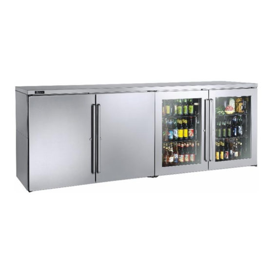
(w/glass door option shown)
Product Series Covered in this manual:
Self-Contained
•
BBS
•
BBSN
•
PTS
•
DZS
•
SDBS
•
SDPS
•
BBSLP
•
DDC
•
DDS
SERVICE MANUAL
Commercial Back Bar Refrigeration
Self-Contained and Remote
BBS60
Remote
•
BBR
•
BBRN
•
PTR
•
SDBR
•
SDPR
•
BBRLP
(w/glass door and solid stainless steel door
Scan here to
download a pdf copy
of this manual.
BBR96
options shown)
Advertisement
Table of Contents

Subscribe to Our Youtube Channel
Related Manuals for Perlick BBS60


Summary of Contents for Perlick BBS60
- Page 1 SERVICE MANUAL Commercial Back Bar Refrigeration Self-Contained and Remote BBS60 (w/glass door option shown) BBR96 (w/glass door and solid stainless steel door options shown) Product Series Covered in this manual: Self-Contained Remote • • • • BBSN BBRN • •...
- Page 2 Back Bar Service Manual Table of Contents 1.0 GENERAL INFORMATION ................1-1 Use of Service Manual ..................1-1 Model Families ....................1-1 2.0 SAFETY INFORMATION ................... 2-1 Refrigerant HFC-134a ..................2-1 Potential Problems with HFC-134a ..............2-1 Service Manual Safety Labels ................2-1 3.0 TROUBLESHOOTING GUIDE –...
-
Page 3: Table Of Contents
Back Bar Service Manual 7.5.3 Replacing Control Module ................. 7-25 7.5.3.1 Removing Dixell Controller ..............7-25 7.5.3.2 Installing Eliwell Controller ..............7-27 7.5.4 Temperature Probe ..................7-28 LED Lighting ....................7-28 7.6.1 Replace LED Light Strip ..................7-28 Replace DC Driver/Inverter ................7-29 8.0 SERVICE INSTRUCTIONS - DOORS, DRAWERS, AND SHELVING ..... - Page 4 Figure 7-1. BBR24 Wiring Diagram ................... 7-2 Figure 7-2. BBR48, BBR72, BBR96 Wiring Diagram ............7-3 Figure 7-3. BBS36, BBS60, BBS84, BBS108 Wiring Diagram ..........7-4 Figure 7-4. BBSN32, BBSN52, BBSN72, BBSN92 Wiring Diagram ......... 7-5 Figure 7-5. BBRN Wiring Diagram ..................7-6 Figure 7-6.
- Page 5 Back Bar Service Manual Table of Tables Table 6-1. System Operating Pressures ................6-3 Table 6-2. Compressor Data..................... 6-6 Table 7-1. Electrical Specifications ..................7-1 Table 7-2. Load Operation Modes ..................7-23 Table 7-3. Controller Where-Used Table ................7-23 Table 7-4. Factory Temperature Settings................7-24 Table 7-5.
-
Page 6: Figure 1-1. Information Plate For Self-Contained Units
If you have any questions or require additional assistance, contact Perlick Customer Service during regular hours of operation. Model Families This manual contains specific instructions for... - Page 7 • Systems or components of the refrigeration operation and care of the Perlick unit. system should not be left open to atmosphere for more than (15) minutes at any time as humidity from the air will enter the system and be absorbed by the oil.
- Page 8 3.0 Troubleshooting Guide – Refrigeration System Use this diagnostic guide to identify issues and to locate applicable instructions within this service manual. This diagnostic guide can be used for any of Perlick’s Back Bar Refrigeration Products. ELECTROCUTION HAZARD!! Never attempt to repair or perform maintenance on the unit until the Main electrical power has been disconnected.
- Page 9 Back Bar Service Manual PROBLEM CAUSE SOLUTION Probe is not connected to the control. Reconnect probe. See Section 7.5.4. Refrigerator is too warm. Air Infiltration (continued) Sealing compound does not form a Refer to Section 1.1. complete seal. Door gasket is damaged or out of place. Refer to Sections 1.1 and 8.6.
- Page 10 Back Bar Service Manual PROBLEM CAUSE SOLUTION Condensate pan overflowing. Remove excess water. Check for the following: • Air infiltration. See Section 6.1. • Doors close completely and seals are intact. See Section 8.6. • Ice buildup. See Section 6.5. •...
- Page 11 Back Bar Service Manual 4.0 Troubleshooting Guide – Electrical System PROBLEM CAUSE SOLUTION Check condensing unit is plugged in. Compressor is not No power to condensing unit. running. Check power at internal receptacle. Check control settings or for bad control. No call for cooling from control.
- Page 12 Back Bar Service Manual PROBLEM CAUSE SOLUTION Restore power to unit. Control not functioning No power to unit. Refer to information plate. See Section 1.0 and Table 7-1 Verify wiring per wiring diagram, Section Incorrectly wired harness. 7.2. Reconnect wires if needed. Replace controller No call for cooling.
- Page 13 Back Bar Service Manual PROBLEM CAUSE SOLUTION Coils Eliwell Control: LED (continued) Controller display is flashing “AH1” Condensing coil is not clean. Clean with soft brush and vacuum. (continued) Fins are bent or damaged. Straighten fins. Probe Probe is not connected to control. Reconnect probe.
- Page 14 Back Bar Service Manual PROBLEM CAUSE SOLUTION Power Dixell Control: LED Controller display is Incorrectly wired harness and/or Verify wiring per wiring diagram, flashing “HA”. Maximum internal wiring connections. Section 7.2. Reconnect wires if needed. temperature alarm. (continued) Fans Evaporator fan is not running. Refer to Evaporator fan is not running Coils...
- Page 15 Back Bar Service Manual 5.0 Troubleshooting Guide – Doors, Drawers and Shelving PROBLEM CAUSE SOLUTION Key won’t come out Key not in proper position. Rotate key to the proper position and after door is locked. remove. Refer to Section 8.4.3. Sliding doors not Replace spring and/or torpedo assembly.
-
Page 16: Figure 6-1. Sealing Compound At Wiring Pass-Through
Back Bar Service Manual 6.0 Refrigeration System Repair Instructions STEP 3. Silicone Seal (RTV type) Air Infiltration Check for complete silicone seal of: Air infiltration can occur in several locations. • Joint where rear wall meets ceiling Note: Unit may manifest longer than normal run •... -
Page 17: Figure 6-4. Remove Condensing Unit Bracket
Back Bar Service Manual Slide Out the Refrigeration Deck STEP 1. Remove grille by removing 1 Phillips head screw at the top center grille and 2 at the bottom edge. STEP 2. Remove square bracket around the front of condensing unit by removing 6 Phillips screws and 2 hex head bolts. -
Page 18: Table 6-1. System Operating Pressures
Back Bar Service Manual STEP 3. Recording pressure System Operating Pressures When installing gauges: Note: To check operating pressures, you must 1. Initially purge manifold set with refrigerant gain access to the service valves. See type used in unit. This avoids introduction of Section 6.4.4. -
Page 19: Figure 6-7. Service Valves
Back Bar Service Manual Service valve positions are as follows: De-Ice Blocked Evaporator Coil – Self-Contained Models Fully Left Back seated with flow from refrigeration system closed. STEP 1. Remove shelves and pilaster from refrigerator section nearest the evaporator coil. STEP 2. -
Page 20: Figure 6-9. Check For Obstructions
The unit must have free air flow to front grille to electrical power has been disconnected. operate properly. Perlick’s warranty does not cover cleaning of Restricted air flow results in high head pressures condenser. and reduction in efficiency due to longer run times. -
Page 21: Table 6-2. Compressor Data
Table 6-2. Compressor Data START WINDING RUN WINDING MODEL RESISTANCE RESISTANCE /FAMILY WIRING Ω AT 77°F Ω AT 77°F RUN/START BBS36 RSIR 8.85 3.85 12.70 BBS60 CSIR 4.15 1.55 5.70 BBS84 CSIR 3.87 1.04 4.91 BBS108 CSIR 3.87 1.04 4.91 BBSN32 RSIR 8.85... -
Page 22: Figure 6-10. Fan Mounting Hardware
Back Bar Service Manual STEP 2. Replace Condenser Fan Motor Cut 2 zip ties holding wire harness to top of the STEP 1. refrigeration module. Remove Refrigeration Deck. See Section 6.2. STEP 3. STEP 2. Disconnect evaporator fan wire leads from main wiring harness. - Page 23 To gain access to compressor, follow instructions in Section 6.2. Before installing gauges, vent hoses and manifold with refrigerant type used in unit. This avoids Compressor should only be replaced with Perlick introduction of air into system. OEM parts. Continue to next page…...
- Page 24 Back Bar Service Manual 2. Purge system through the high side until a STEP 4. nominal amount of refrigerant is purged out Service valve positions are as follows: of the low side. 3. Then “weigh in” the correct total charge into Fully Left Back seated with flow from system.
-
Page 25: Table 7-1. Electrical Specifications
Verify adequate power is supplied. Table 7-1. Electrical Specifications Unit Type Model Number Running Load Amps Electrical Supply Electrical Connection Self-Contained BBS36 120 VAC/60 Hz/1 Ph Cord Connected BBS60 BBS84 BBS108 BBSLP36 BBSLP60 BBSLP84 BBSLP108 BBSN32 BBSN52 BBSN72 BBSN92 DDS36... -
Page 26: Wiring Diagrams
Back Bar Service Manual Wiring Diagrams Figure 7-1. BBR24, BBRN40 Wiring Diagram Return to Table of Contents Electrical System Repair Instructions Page 7-2... - Page 27 Back Bar Service Manual Figure 7-1. BBR24, BBRN40 Wiring Diagram Return to Table of Contents Electrical System Repair Instructions Page 7-3...
- Page 28 Back Bar Service Manual Figure 7-2. BBR48, BBR72, BBR96, BBRN60, BBRN80 Wiring Diagram Return to Table of Contents Electrical System Repair Instructions Page 7-4...
- Page 29 Back Bar Service Manual Figure 7-2. BBR48, BBR72, BBR96, BBRN60, BBRN80 Wiring Diagram Return to Table of Contents Electrical System Repair Instructions Page 7-5...
-
Page 30: Bbsn32
Back Bar Service Manual Figure 7-3. BBS36, BBS60, BBS84, BBS108, BBSN32, BBSN52, BBSN72, BBSN92 Wiring Diagram Return to Table of Contents Electrical System Repair Instructions Page 7-6... - Page 31 Back Bar Service Manual Figure 7-3. BBS36, BBS60, BBS84, BBS108, BBSN32, BBSN52, BBSN72 and BBSN92 Wiring Diagram Return to Table of Contents Electrical System Repair Instructions Page 7-7...
- Page 32 Back Bar Service Manual Figure 7-3. BBS36, BBS60, BBS84, BBS108, BBSN32, BBSN52, BBSN72 and BBSN92 Wiring Diagram Return to Table of Contents Electrical System Repair Instructions Page 7-8...
- Page 33 Back Bar Service Manual Figure 7-4. BBR24, BBRN40 Wiring Diagram Return to Table of Contents Electrical System Repair Instructions Page 7-9...
- Page 34 Back Bar Service Manual Figure 7-4. BBR24, BBRN40 Wiring Diagram Return to Table of Contents Electrical System Repair Instructions Page 7-10...
- Page 35 Back Bar Service Manual Figure 7-5. BBR48, BBR72, BBR96, BBRN60 and BBRN80 Wiring Diagram Return to Table of Contents Electrical System Repair Instructions Page 7-11...
- Page 36 Back Bar Service Manual Figure 7-5. BBR48, BBR72, BBR96, BBRN60 and BBRN80 Wiring Diagram Return to Table of Contents Electrical System Repair Instructions Page 7-12...
- Page 37 Back Bar Service Manual Figure 7-6. PTS36, PTS60, PTS84 Wiring Diagram Return to Table of Contents Electrical System Repair Instructions Page 7-13...
- Page 38 Back Bar Service Manual Figure 7-6. PTS36, PTS60, PTS84 Wiring Diagram Return to Table of Contents Electrical System Repair Instructions Page 7-14...
- Page 39 Back Bar Service Manual Figure 7-6. PTS36, PTS60, PTS84 Wiring Diagram Return to Table of Contents Electrical System Repair Instructions Page 7-15...
- Page 40 Back Bar Service Manual Figure 7-7. PTR48, PTR72 Wiring Diagram Return to Table of Contents Electrical System Repair Instructions Page 7-16...
- Page 41 Back Bar Service Manual Figure 7-7. PTR48, PTR72 Wiring Diagram Return to Table of Contents Electrical System Repair Instructions Page 7-17...
- Page 42 Back Bar Service Manual Figure 7-8. DDS, DDC Wiring Diagram Return to Table of Contents Electrical System Repair Instructions Page 7-18...
- Page 43 Back Bar Service Manual Figure 7-8. DDS, DDC Wiring Diagram Return to Table of Contents Electrical System Repair Instructions Page 7-19...
- Page 44 Back Bar Service Manual Figure 7-8. DDS, DDC Wiring Diagram Return to Table of Contents Electrical System Repair Instructions Page 7-20...
- Page 45 Back Bar Service Manual Figure 7-9. BBRLP48, BBRLP72, BBRLP96 Wiring Diagram. Return to Table of Contents Electrical System Repair Instructions Page 7-21...
- Page 46 Back Bar Service Manual Figure 7-9. BBRLP48, BBRLP72, BBRLP96 Wiring Diagram Return to Table of Contents Electrical System Repair Instructions Page 7-22...
-
Page 47: Table 7-2. Load Operation Modes
Back Bar Service Manual Load Operation Modes Table 7-2. Load Operation Modes LOAD COOLING MODE OFF MODE DEFROST MODE Compressor Energized De-Energized De-Energized Condenser Fan Energized De-Energized De-Energized Evaporator Fan Energized Energized Energized Mullion Heaters Energized Energized Energized Eliwell Controller Display No icon illuminated Dixell Controller Display No icon illuminated... -
Page 48: Table 7-4. Factory Temperature Settings
Dixell Controller: Reset Factory Parameter Settings • Scroll through the various applications (AP1- AP2-AP3) using the keys; • Contact Perlick. • Select the desired application using the 7.5.2 Eliwell Controller: Reset Factory key (AP3 in the example) or cancel the Parameter Settings... -
Page 49: Step
Back Bar Service Manual 7.5.3 Replacing Control Module 7.5.3.1 Removing Dixell Controller Tools required STEP 1. Remove the grille by removing 3 Phillips head screws, one at the top center and two at the bottom edge. STEP 4. Cut 2 zip ties holding wire harness to top of the STEP 2. -
Page 50: Step
Back Bar Service Manual STEP 9. STEP 6. Remove green probe connector from controller. Disconnect mullion heater wire leads from the main wiring harness. STEP 10. Remove controller assembly from the unit. STEP 7. Disconnect DC driver leads from the main wiring STEP 11. -
Page 51: Step
Back Bar Service Manual STEP 14. STEP 2. Remove screw holding probe “mass” to the probe Attach probe and mass onto probe bracket with bracket and remove the probe. screw. STEP 3. Use pliers if needed to secure probe notch to sheet metal probe bracket. -
Page 52: Table 7-5. Temperature - Resistance Values
Back Bar Service Manual 7.5.4 Temperature Probe TEMPERATURE TEMPERATURE RESISTANCE (°C) (°F) (OHMS) • Each refrigerated zone has one 10K 4911 ohm NTC probe, which senses 4160 compartment temperature. Sensing 3536 probe is located behind evaporator fan • To replace temperature probe, refer to panel. -
Page 53: Step
Back Bar Service Manual If not within range printed on the part, replace the part. STEP 3. Disconnect DC driver leads from the main wiring harness. Figure 7-4. Interior LED Light Replace DC Driver/Inverter STEP 1. Locate DC Driver/Inverter on ceiling of refrigeration compartment. -
Page 54: Figure 8-1. Door Removal
Right Hinging Figure 8-1. Door Removal 67439L Left Hinging STEP 2. Pull door to the side and then lower the door. Tools required Perlick Hinge Kit Return to Table of Contents Service Instructions - Door, Drawers and Shelving Page 8-1... -
Page 55: Figure 8-2. Hinge Removal
Back Bar Service Manual STEP 3. STEP 5. Remove top and bottom hinge brackets. Retain Using screws removed in step 3, install top and screws for later use. See Figure 8-2. bottom hinge brackets from kit. See Figure 8-3. Figure 8-3. Hinge Installation Figure 8-2. -
Page 56: Figure 8-5. Removing Front Panel
Back Bar Service Manual STEP 7. STEP 9. Remove front panel from door assembly by Insert V-block into door bottom hinge bracket removing inner mounting screws (4 per side) and attach with e-clip. See Figure 8-6. Note the from perimeter of door assembly. See Figure 8-5. orientation of V-block. -
Page 57: Figure 8-8. Installing V-Block
Back Bar Service Manual STEP 11. STEP 13. Place lower V-block into lower cabinet hinge with Insert and tighten lower hinge pin to complete notch parallel to cabinet. See Figure 8-8. assembly. Replace Door Hinge See Section 8.2 for hinge replacement instructions. -
Page 58: Figure 8-11. Door Track
Back Bar Service Manual 8.4.2 Adjusting Door Spring Tension STEP 4. Feed into next notch to tighten/loosen. Tools required STEP 5. Tighten screw. Tension spring is in upper track of each door. Drawer & Shelf Slides 8.5.1 Shelving Adjustment Screw Completely empty shelf or drawer before removing. -
Page 59: Figure 8-13. Removing/Installing Drawer
Back Bar Service Manual 8.5.2 Drawer Divider Adjustment STEP 4. Place drawer on to the extenders, making sure wheels engage the slots on each side. Completely empty shelf or drawer before STEP 5. removing. Push drawer all the way in, then pull drawer out STEP 1. -
Page 60: Figure 8-14. Custom Panel
Back Bar Service Manual Replace Door Handle Custom Overlay Panels Tools required Tools required 3/8” Remove front panel from door assembly by STEP 1. removing inner mounting screws (4 per side) Remove door gasket. See Section 8.6. from perimeter of door assembly. See Figure 8-14. -
Page 61: Replacement Parts
Back Bar Service Manual 9.0 Replacement Parts For parts ordering call (844) 411-8050. Refrigeration Module (BBS, BBSN, PTS, SDBS, SDPS, DDS, DDC Model Series) Return to Table of Contents Replacement Parts Page 9-1... - Page 62 Back Bar Service Manual BBS, BBSN, PTS, SDBS, SDPS, DDS, DDC MODELS 3&4- ITEM 1-DOOR 2-DOOR DESCRIPTION DOOR NUMBER QTY. QTY. QTY. Condensing Unit, 1/5 H.P. 115V, BOM #515301064 Condensing Unit, 1/4 H.P., 115V, BOM #515301063 Condensing Unit, 1/3 H.P. 115V, BOM #515301062 Screw, Phillips Truss Head Machine Screw, Thread Cutter, Hex Washer Head Screw, Phillips Truss Head Sheet Metal...
- Page 63 Back Bar Service Manual BBS, BBSN, PTS, SDBS, SDPS, DDS, DDC MODELS 3&4- ITEM 1-DOOR 2-DOOR DESCRIPTION DOOR NUMBER QTY. QTY. QTY. L & S Line, 3 & 4 Door Power Cord, with Molded Receptacle Wire Harness, Refrigeration Module Bracket, Controller Mounting Screw, Phillips Head Screw, Phillips Head Machine Return to...
-
Page 64: Refrigeration Module (Bbslp Model Series)
Back Bar Service Manual Refrigeration Module (BBSLP Model Series) Return to Table of Contents Replacement Parts Page 9-4... - Page 65 Back Bar Service Manual BBSLP MODELS 3&4- ITEM 1-DOOR 2-DOOR DESCRIPTION DOOR NUMBER QTY. QTY. QTY. Condensing Unit, 1/3 HP, 115V Condensing Unit, 1/4 HP 115V Condensing Unit, 1/5 HP, 115V Base, High Side Bracket, Hold Down, Compressor Panel, Baffle, Compressor Rail, Condensate Pan Panel, Outer Side, High Side Panel, Inner Side, High Side...
- Page 66 Back Bar Service Manual BBSLP MODELS 3&4- ITEM 1-DOOR 2-DOOR DESCRIPTION DOOR NUMBER QTY. QTY. QTY. L & S Line, 3 & 4 Door, Back Bar Wire Harness, Fan Motors Harness 12VDC Split Male-Female Grille, Front, S.S. Grille, Front, Black Vinyl Customer Option Screw, Sheet Metal, #6 X 3/4", Phillips Cover, Dc Driver, Low Ht.
-
Page 67: Refrigeration Module (Dzs60 Model Series)
Back Bar Service Manual Refrigeration Module (DZS60 Model Series) Return to Table of Contents Replacement Parts Page 9-7... - Page 68 Back Bar Service Manual DZS60 MODELS ITEM DESCRIPTION QTY. NUMBER Condensing Unit, 1/4 H.P., 115V Screw, Machine, #8-32 x 2-1/2" Lg, Phillips Truss Head Screw, Thread Cutter, 1/4-20 x 5/8 Hex Washer Head, Type 23, Steel Screw, Sheet Metal, #6 x 1/2", Type "A", PH Truss Head - Full Contoured, 18-8 Screw, Sheet Metal, #10 x 1", PH Pan Head, Type "B", Steel, Hardened Screw, #10 X 1/2"...
- Page 69 Back Bar Service Manual DZS60 MODELS ITEM DESCRIPTION QTY. NUMBER Baffle, Compressor Bracket, Compressor L & S Line, 2 Door Back Bar Power Cord with Molded Receptacle, 14/3, Back Bar Wire Harness, Refrigeration Module, Back Bar Controller Board-Damper, Dual Zone Commercial Controller Mounting Bracket Screw, #10 X .500 PH TRUSS HEAD Plated Screw, Machine, 8-32,2-1/2"...
-
Page 70: Refrigeration Module (Dzs36 Model Series)
Back Bar Service Manual Refrigeration Module (DZS36 Model Series) DZS36 MODELS ITEM DESCRIPTION QTY. NUMBER Condensing Unit, 1/5 H.P. 115V Screw, Machine, #8-32 x 2-1/2" Lg, Phillips Truss Head Return to Table of Contents Replacement Parts Page 9-10... - Page 71 Back Bar Service Manual DZS36 MODELS ITEM DESCRIPTION QTY. NUMBER Screw, Thread Cutter, 1/4-20 x 5/8 Hex Washer Head, Type 23, Steel Screw, Sheet Metal, #6 x 1/2", Type "A", PH Truss Head - Full Contoured, 18-8 Screw, Sheet Metal, #10 x 1", PH Pan Head, Type "B", Steel, Hardened Screw, #10 X 1/2"...
- Page 72 Back Bar Service Manual DZS36 MODELS ITEM DESCRIPTION QTY. NUMBER Wire Harness, Refrigeration Module, Back Bar Controller Mounting Bracket Controller Board-Damper, Dual Zone Commercial Screw, #10 X .500 PH Truss Head Screw, Machine, 8-32,2-1/2" Lg Phillip Truss Head, Steel, Black Zinc, Plated Return to Table of Contents Replacement Parts...
-
Page 73: Dds60
Back Bar Service Manual Refrigeration Module (DDS60-IR, DDS84-IR, DDS108-IR Model Series) Return to Table of Contents Replacement Parts Page 9-13... - Page 74 Back Bar Service Manual DDS60-IR, DDS84-IR, DDS108-IR MODELS 3&4- ITEM 2-DOOR DESCRIPTION DOOR NUMBER QTY. QTY. Condensing Unit, 1/3 H.P. 115V Condensing Unit, 1/4 H.P., 115V Screw, Machine, 8-32, 2-1/2" Lg Phillip Truss Head, Steel, Black Zinc, Plated Screw, Thread Cutter, 1/4-20 x 5/8 Hex Washer Head, Type 23, Steel Screw, Sheet Metal, #10 x 1", PH Pan Head, Type "B", Steel, Hardened Screw, #10 X 1/2"...
- Page 75 Back Bar Service Manual DDS60-IR, DDS84-IR, DDS108-IR MODELS 3&4- ITEM 2-DOOR DESCRIPTION DOOR NUMBER QTY. QTY. Wire Harness, Refrigeration Module, Back Bar Controller Mounting Bracket Panel, Back, Flush, High Side, Back Bar Bracket, Mounting, Flush Back Panel, Back Bar Screw, #10 X .500 PH Truss Head Return to Table of Contents Replacement Parts...
-
Page 76: Fan Motor Assembly Parts (Self-Contained Model Series)
Back Bar Service Manual Fan Motor Assembly Parts (Self-Contained Model Series) SELF-CONTAINED MODELS ITEM DESCRIPTION QTY. NUMBER Motor, Fan Panel, Fan Mounting Panel, Inner Grille Screw, Motor Mounting Screw, Grille Mounting Guard, Product Screw, Guard Mounting Return to Table of Contents Replacement Parts Page 9-16... -
Page 77: Low Profile Evaporator Parts (Bbslp Model Series)
Back Bar Service Manual Low Profile Evaporator Parts (BBSLP Model Series) LOW PROFILE MODELS ITEM DESCRIPTION QTY. NUMBER Fan, Evaporator Panel, Fan Mounting Screw, Fan Mounting Grille Screw, Grille Mounting Handle, Guard Screw, Guard Handle Mounting Return to Table of Contents Replacement Parts Page 9-17... -
Page 78: Remote Evaporator Parts (Bbr, Bbrn, Ptr, Sdbr & Bbrlp Model Series)
Back Bar Service Manual Remote Evaporator Parts (BBR, BBRN, PTR, SDBR & BBRLP Model Series) REMOTE MODELS ITEM DESCRIPTION QTY. NUMBER Motor, Fan Panel, Fan Mounting Bracket, Fan Control, Temperature Pan, Evaporator Bushing, 1.75" I.D. Guard, Plastic Fan Return to Table of Contents Replacement Parts Page 9-18... - Page 79 Back Bar Service Manual REMOTE MODELS ITEM DESCRIPTION QTY. NUMBER Fan Panel, Evaporator (Right) Fan Panel, Evaporator (Left) Plug, Dome Motor, Fan Blade, Fan Evaporator Assembly Coil, 21” Fin Tube, Evaporator Outlet Tube, Evaporator Inlet Clamp, Control Bulb Silicone Return to Table of Contents Replacement Parts Page 9-19...
- Page 80 • • • 8300 West Good Hope Road Milwaukee, WI 53223 • • Toll Free 800.558.5592 Fax 414.353.7069 ww.perlick.com...
Need help?
Do you have a question about the BBS60 and is the answer not in the manual?
Questions and answers